Completed project: "Fenrir"

I just finished this pair of bookshelves a couple weeks ago, using the Rival Acoustics R176-P-08 carbon-paper woofers, and the Wavecor TW022WA06-4 waveguided 22mm tweeters. 18 ltrs tuned to 40Hz for an F3 just below that, and an FR measurement that sits mainly at +/-2dB, while having low HD.

I'll attach all of the documentation in photos. Thanks for looking, and please ask if you have any questions!

Later,
Wolf

PS- more photos in the second post...

Attachments

  • Fenrirbox.jpg
    Fenrirbox.jpg
    216.1 KB · Views: 2,289
  • FenrirMach.jpg
    FenrirMach.jpg
    95.5 KB · Views: 2,259
  • FenrirVoiced_1-6thFR.jpg
    FenrirVoiced_1-6thFR.jpg
    65.4 KB · Views: 2,211
  • FenrirVoiced_nosmoothing.jpg
    FenrirVoiced_nosmoothing.jpg
    71.5 KB · Views: 2,189
  • FenrirVoicedHD_-9dB.jpg
    FenrirVoicedHD_-9dB.jpg
    132 KB · Views: 2,189
  • FenrirXmax.jpg
    FenrirXmax.jpg
    86.7 KB · Views: 515
  • FenrirXover.png
    FenrirXover.png
    107.4 KB · Views: 630
  • FenrirZ.jpg
    FenrirZ.jpg
    121.4 KB · Views: 633
  • Rival R176P08-1.jpg
    Rival R176P08-1.jpg
    92.5 KB · Views: 340
  • WavecorTW022WA06-4-1.jpg
    WavecorTW022WA06-4-1.jpg
    94.7 KB · Views: 322

Basic Crossover Question

I'm trying to crossover my Dayton RS225-8 at 1200hz. I realize I'm pushing them a little high to avoid breakup but they are what I have to use without purchasing new drivers. No measuring capability here and don't understand simulation software. I'm using MH-Audio calculators. The calculator asks for driver impedance at XO point. Factory specs show about 9 ohms impedance at 1200hz. Do I use this impedance AND add a Zobel to flatten impedance or just use this? Thanks for any suggestions. By the way they are in a 42 liter BR cabinet with a 10" wide baffle. Also wondering if baffle step is needed. Thanks again.

evaluating used power transformer for use in Matchless Spitfire clone

building a Matchless Spitfire clone, and was lucky enough to find an old transformer with very close to appropriate voltages! 6.3, 5, and a HT+ of about 265, close enough to the 285 on the schematic and a bit gentler on those super hot biased power tubes. what's really neat is it's got a dial on the side for different wall voltages, so it could be used in other countries, and it's got a 145VAC input setting... which is pretty strange, but basically constitutes a low power mode. i wonder what this came from...

i want to make sure i'm using best practices when trying to make this sucker work, so i wanted to run a few things by you guys.

first - the thing is almost 2x as big as the Hammond xfmr recommended to replace a Spitfire, so i figure i'm not pushing any power handling limits, especially with only 2x 6BQ5, 2x12AX7 and 1x GZ34. is this a safe assumption?

second, there's one mysterious green lead coming from the PT that doesn't read continuity or any kind of resistance to any other lead, and sits at about 82VAC... what the hell is this?? i was thinking electrostatic shield until i read the voltage... could it be a shield and the voltage indicates something is wrong internally? all the other windings tested as expected.

third, i want to understand proper mounting, combined with proper grounding of the outer shell. i've seen a lot of conflicting opinions on this. to avoid affecting the flux at all, i was planning on mounting it with brass bolts with nylon washers insulating it from the chassy at all points. but then i've seen others saying that it needs to be ground referenced at one point... and i'm not sure how this ties in with the 'air gap' that should exist. my attempt to combine these leaves me with this plan:
  • brass bolts with nylon washers insulating from the chassy at all but one point
  • for one of the bolts, use a conductive washer at the chassy attachment for a ground reference (also just considering a terminal and wire running to the star ground point at the neg. terminal of the filter cap)
  • make sure that the rest of the transformer shell does not make contact with the chassy (this is what i'm assuming is the 'air gap') except at that one grounding point

fourth, what do you recommend in terms of a combination of nuts and washers in order to mount this securely? my thought was internal toothed washer with the teeth facing the chassy, then nylon washer, then nut. is a nyloc nut any help here?

fifth, should the same general practices in the last two questions apply to mounting OT's and chokes? i already know about how they should be oriented in reference to each other, just wondering about grounding, insulation, mounting etc.

thanks in advance!!

Power supplies in a separate chassis

Quick question about physical layout options in a preamp + power amp setup:

If using 2 chassis, would it be beneficial to arrange the setup so that one chassis would contain all power supplies, and the other everything else (input devices and the amps)? The traditional way would be to have the preamp and power amp in their respective chassis containing their own power supplies.

My assumption and understanding is that by isolating the transformers and power supplies to their own chassis, possible hum and noise issues could be prevented. Is this the correct way to think about this?

PMC inspired speakers

Dear all,

After hours or reading and as a total beginner on speaker design, I come here to explain my project and my questions.

Few month ago I discovered the PMC twenty5 range and especially there tower speaker (23i, 24i and 26i). 2 way speakers MLTL type. Completely amazed by the design (and their price), I’m serching for a way to make an inspired version of those speakers, especially the 24i tower speakers.
https://pmc-speakers.com/products/archive/archive/twenty524
https://www.lbtechreviews.com/test/speakers/pmc-twenty5-24i

I found many informations on the web (external cabinet dimensions, cutout…) but not much about the characteristics of their speakers ( 17cm woofer g-weave cone / 19mm tweeter Sonomex dome – that’s all).

Which speakers would you recommend to use in such project ? Do you think it is reasonable to try to reuse the costless Amiga MT speakers and associated crossover (Dayton audio RS180S-8 and Perless DX25TG59-04) in such transmission line as they have very similar dimensions (but certainly not similar characteristics).

Attachments

  • Capture 24i.JPG
    Capture 24i.JPG
    40.5 KB · Views: 262
  • 12PMC_Twenty523_12.jpg
    12PMC_Twenty523_12.jpg
    33.8 KB · Views: 264

IDC Insertion Tool

I bought some header/harness combos for a project and ended up with some 24 awg, IDC connectors. I looked around for an insertion tool and bought a punch-down tool which was too big. I ended up using a small screw driver, That was messy and took a long time, but it did work. I certainly like the IDC idea - smaller, cleaner, and cheaper than Molex-type crimp inserts. But I wonder if there is some tool that would make this easier.

Triton MLTL dearly missing a VWR126X. Alternatives?

Hi. After noticing my Triton MLTL didn't sound right, I found that the basket of one of the VWR126X has broken, tearing the spider in the process (no idea how or when it happened). So I'm looking for alternatives:
  • A woofer that could replace the VWR126X in the Triton, although I doubt one exist as the Triton was designed specifically for the VWR126X;
  • A design that would take advantage of the remaining three VWR126X (I guess one will feel lonely) and the two LD25X tweeters;
  • Feeling very very lucky, someone have a VWR126X (or a couple) collecting dust.
Thanks for your suggestion.

Improving simple CCS PSRR by 30 dB

It was noted in another thread that ready-made CCS, as current regulator diodes (CRD), are better than discrete ones. I had CCS on breadboard and those diodes laying around, so decided to check. Comparison between “two diode & BJT” CCS vs. Semitech current regulator diode (two terminal JFET CCS) at 1.5 mA current was made.

To my surprise, CRD CCS is better.

Working on some design, you are guaranteed to reinvent the wheel several times at least. I found that similar proposal was mentioned before on this forum (by peufeu I think), but to find that right choice of search phrases or pure luck is needed. As a newcomer, I can only notice that vast knowledge is buried inside countless threads, waiting to be discovered again.
I won’t discuss other smart and much better CCS designs that can be found here, but simple two diode CCS as found in the article (Figure 4A):

https://audioxpress.com/assets/upload/files/Sources_101_P1.pdf

Replacing resistor R1 with simple CRD, decreases Q1 Vbe modulation by supply ripple and brings + 30 dB improvement in the PSRR of CCS. This is interesting because existing CCS can be upgraded by simple one component exchange.

Edit: some find thread title offensive. I’m always for some humor as we are not discussing life and death matters. So, I’ve made some edits and requested title change.

Attachments

  • CRD diode CCS vs BJT CCS.PNG
    CRD diode CCS vs BJT CCS.PNG
    57.9 KB · Views: 938
  • Modified BJT CCS PSRR comparison.PNG
    Modified BJT CCS PSRR comparison.PNG
    57.6 KB · Views: 931
  • Like
Reactions: YashN

12” ported cabinet or 15” sealed cabinet?

Hi I’m a new member who is very green when it comes to the audio vocabulary, so please bare with me.
I am a drummer and was considering building a 3 way speaker. I have a few spare drum shells and was considering turning one into a woofer enclosure.
I have read some specs on a 15” woofer that said a 63 litre/16.5 gallon sealed cabinet would suit , fortunately my 18” maple drum shell fits the bill perfectly so I have a few questions.
1) Would I get the same amplitude from a 15” sealed woofer as a 12” ported but with improved sound characteristics?
2) if I heavily dampened the shell and reduced its volume considerably would I need to increase the size of the shell I use? (I hear that with a ported cabinet if you dampen the cabinet you may be able to reduce its size by up to 20%) I guess I’m also wondering if a sealed woofer requires dampening at all.
3) Would a cylinder style cabinet net me any benefits rather than going with a standard square/rectangle design?

Thankyou everyone I have so many questions but I think it’s best to go one thing at a time.

20k Stepped Attenuator with loudness tap?

This isn't critical, but if I could find a decent/high quality replacement for the volume attenuator in my Kenwood 700c preamp I'd be tempted. It is a 2 gang 20k part with loudness tap.
Are there any available with a loudness tap, or could I add a loudness tap to one?

The original works but needs periodic cleaning. I can deal with that but thought I'd see if anyone here had anything to suggest. This is my main preamp. It is a truly great unit. Many units have crossed my bench but none have beat it and few come close.

Mono, the best approach

I have no exposure to mono at all. But I have someone who I built a Paradise for asking for a solution to a dedicated mono setup.

Is he best off using a Y splitter between tonearm lead and into both inputs of a dual mono phonostage?

Or, is he better off getting another single channel of a Paradise and using a y splitter on the output?

Assume cost doesn't matter, and he's using a Majiyma dedicated mono cartridge.

All opinions appreciated.

Broken speaker cover frame - Fixable?

I picked up these PSB Stratus Goldi speakers a few days ago and one of the frames is broken. Looks to be some kind of fiberboard. Can this be repaired somehow, or am I looking at having to replace them altogether? I'd also like to replace the cloth, any suggestions/caveats welcome!

Attachments

  • image000000.jpg
    image000000.jpg
    447.6 KB · Views: 132
  • image000001.jpg
    image000001.jpg
    500.9 KB · Views: 131

An alternative to Goland Audio DVD Creator suggestions ?

Hi
Once again I am having trouble with trying to burn hirez 24/96 Audio dvds (Not DVD Audios)
This simple easy sytem seems to have gone wrong after a Microsoft update to Windows 10.

Does anyone have a simple working alternative as I had tried a good few that do not take either 24 bit or 24/96 sampling of wav.
Many thanks . As I am considering an extra old hard drive with a version of earlier win program as a desperate last resort.

What is the purpose of these caps?

I have one of the earlier versions of the ShortestWay 51+ amp (also referred to as the SW51 amp). This amp was created by a SBAF community member. It's a SET amp that uses 6Z51P/EF184 tubes.

I had a look at the PCB and was wondering if someone could tell me can what the purpose of these 2 film caps were:


The caps are WEIDY W313A102-J6:
  • Capacitance is 0.0010 uF / 1000 pF
  • Voltage rating of 1000/1250 Vdc

Thanks in advance.

Is there anyone in New England that is legitimately interested in audio R&D?

I've been on a research and development montage in the audio field for almost 10 years now and at this point I'm becoming overwhelmed with everything that I am working on.
After thousands and thousands and thousands of hours of R&D, I can confidently say that I know the path to achieve perfect sound reproduction, however I can no longer do it alone.
I will soon be starting a company showcasing the fruits of my labors but the R&D portion is overwhelming me even without the burden of running a company.
I am wondering if there are any souls in New England that are passionate about progressive audio research and development. Even if you have zero knowledge and would be willing to learn. The ability to think creatively and a results driven mindset is all I need.
I already know the answer but I figured I would ask anyway.
I'd be willing to move elsewhere if I found such a person outside of my region as well, but that would take some convincing.

Advice for newbie crazy enough to want to build a DAC inside a Keyboard

Hello diyAudio, this is my first post here. I have some experience programming in C on embedded systems (mostly on a TI ARM micro-controller). I have been learning KiCAD and about PCB design, since I want to design and manufacture my own 60% keyboard PCB. I am almost nearing completion of my CNC Milling machine to make metal cases for custom mechanical keyboards. However, I had the somewhat crazy (and possibly stupid, who knows) idea of integrating a DAC and headphone amplifier into a keyboard PCB (or daughter board if possible in the cases I plan on designing). I understand at a basic level of what a DAC does along with ADCs, along with what an Amp is supposed to do. Since this would be for a keyboard that is communicating via USB, I have read that I should use I2S in asynchronous mode between the micro-controller and the DAC. I am thinking of using an STM32F411RET micro-controller which seems to have a decent amount of grunt along with what seems to be a good enough I2S interface and it is already compatible with the popular open-source firmware for custom mechanical keyboards, QMK.

This is pretty much where my knowledge ends. I have looked at pictures of some of the DAC designs featured in this forum, and there appears to be a lot more to a proper DAC than just sending my I2S signal to a DAC IC and then feeding that signal through a few capacitors to an amp and calling it good. I am still learning about the theory when it comes to properly designing circuits. I am a computer science student, and not an electrical engineer. There is also probably a lot of domain knowledge when it comes to audio and music too for designing circuits for this purpose. The most I've seen of DIY kits for DACs is on AMB's website, but I don't understand their designs due to my ignorance. I would appreciate any advice you guys are willing to give, especially in learning the fundamentals of designing a decent DAC circuit controlled by a micro-controller which is talking to a computer over USB. I also have to figure out the headphone amplifier, but I believe this part of the forum is dedicated for DAC stuff and things similar to that. Just keep in mind that I am still trying to learn a lot of the terminology involved, such as reading about FIFO's which is more of data structure concept for queues in my head vs whatever is being used to build a DAC in hardware.

More Adventures with Class D

I added a follow up to the article I wrote about my journey with an ICE Class-D Amplifier build I recently finished.....Hope you enjoy
"Back in school days getting a “D” was a bad thing. I had friends that got very good at changing a D to a B on their report cards! But I’m here to tell you that in this case, a “D” is a VERY GOOD thing. I’ve been in the HiFi retail business for near 50 years. I’ve had the luxury of being able to audition dozens if not hundreds of higher end HiFi components at home for extended periods of time. It always boiled down to “Length of Listening”….Some amplifiers and/or speakers were simply unlistenable for longer than 30 minutes or so. They were somehow fatiguing and I would simply shut them off and do something else. Many of these items were amazing on first few minutes of listening, but then grew very tiring and just not interesting to listen to the music any longer. Some components would put me into some kind of HiFi nirvanas and I’d be listening until the wee hours of the morning. I simply didn’t want the session to end.
Well, last night was one of those LONG nights! Using the ICE amp with a Zero Zone Conrad Johnson clone tube preamp and a Node2i/Gustard X-16 DAC playing Tidal direct, into my KEF LS50 Metas, I was smitten! And I didn’t hit the sack until well after midnight.
This amplifier defies all logic. $300, Kit Built, sparse parts, the size of a small box of cigars, doesn’t even get warm…….and it holds fort with my acclaimed Nelson Pass First Watt F5v2!…….But it has better bass!
Maybe it’s my near 70 year old hearing. Maybe I’m easily sonically pleased. But I don’t think so. During COVID, I’ve bought so many amplifiers and other HiFi gear and returned it because it sounded horrible. I can’t hear anything above 15Khz, but I can hear sound stage, imaging, air around the instruments, dynamics…..and I believe these things are more important to good HiFi that frequency response. And this ICE amplifier offers these attributes up in shovels full!
The question I now have to ask…..How much better does a $XXXXX.xx Jeff Rowland Class-D amplifier sound? Diminishing returns you say?
Yup, we got ourselves a VERY interesting hobby!"
for the full article: www.rvbprecision.com

Low Cost Minimalist Speaker Design

Building on the open baffle design I created earlier, quite successful in its own way, once again I started musing about another design, this one with a large bass driver, using low cost components and easy to build.

The current design is a result of many influences: first of all the rising and not inconsiderable cost of speaker drivers compared to a complete used speaker set: as low as $10 per pair for a vintage Sony or other brand. Given these costs it simply does not make sense to build one. The other driver, if I may call it that, is the combination of an equalizer on my music player (Musicolet) and the Sony XB10 Bluetooth speaker pictured. It is only after a some time that I began to appreciate the little speaker's ability to reproduce voices and the mid-range well, and bass, and, with some equalizer adjustments, a balanced clear sound across the audible range, with all the sounds being heard. Could a small speaker really produce such bass? Well hes, due to some passive radiator arrangement within, still it did not change the size of it.

Preferring two speakers, even two left channel speakers hooked up in series to a single mono source, I set out to design another set of speakers, with some new features.

For reference, here are my Desktop Open Baffles (sadly, dismantled) and my Sony BT Speaker.

Attachments

  • obspkr.png
    obspkr.png
    67 KB · Views: 183
  • BTspkr.png
    BTspkr.png
    51.1 KB · Views: 183

Garrard 42M drops on 1 record.

I have a Garrard 42M that I recently bought and put through the usual cleaning and re-lubing. I managed to get is all working, except for one issue.

When I use the cycle function it is able to drop a single LP without a problem. But if I put more than one LP in the stack it won't even drop the first one. I tried various other records on the bottom, and various number in the stack. But it will not function correctly.

I noticed what appears to be an anamoly but with only 1 changer to look at I'm not sure. When it cycle the small inner lever that pushes the record on the bottom over so it can drop down, before it goes to the right, it goes to the left away from the direction it is supposed to go.

I am thinking perhaps I have the roller that moves that in the wrong place on the cycle cam. Anybody have a Garrard 42M or similar they can look at? Confirm that it does not go left and then right, but only to the right and back to drop a record.

Drop in TDA1541 upgrade board?

I've just spotted a small PCB for sale that allows you to double / parallel a TDA1541 in a CD player or DAC.

It has the positions around each DIP socket to install decoupling capacitors.

I've a Marantz CD-65. It's one of the models where the factory decouplers are underneath the PCB rather then next to the DAC.


Woulda a PCB drop in, between the TDA1541 and the main PCB (with DIP socket added) be a suitable way to move these decoupling capacitors to the top.
I've read you don't actually need to remove the factory ones when upgrading them, I'm pretty sure I read of folk simply soldering on the the same points the factory ones do.

But would the idea of a effective daughter board to move these caps to the top, and ease upgrade, actually work? Or am I missing something in my naivety?

Zeus h5000

Hello everyone ! I have this amp to repair and I have blown transistors! Among the damaged components I have this component with the code EN3A11! does anyone know what kind of transistor it is? Or do you by any chance have the schematic of the amplifier?

Attachments

  • 20220303_153520.jpg
    20220303_153520.jpg
    444.7 KB · Views: 126
  • 20220303_153514.jpg
    20220303_153514.jpg
    631 KB · Views: 130
  • 20220303_153507.jpg
    20220303_153507.jpg
    549.9 KB · Views: 123

Hifisonix Soft Start + DC Blocker

I've just completed building and testing a soft start DC blocker ('SSDCB') board.
Slide13.JPG


You can read about it here:- https://hifisonix.com/projects/soft-start-dc-blocker-for-mains/

Here's a presentation you can download https://hifisonix.com/wp-content/uploads/2022/01/DC-Blocker-Soft-Start.pdf

Here's a video about DC on the mains by Paul Gowan of PS Audio DC on the Mains

The circuit uses a 32mm Ametherm thermistor to provide 10A current limiting for 3~5 seconds after mains power is applied with a fast (<0.5sec) reset when power is removed. A separate function provides DC blocking to remove the annoying audible transformer 'growling' that arises from DC on the mains.

Slide5.JPG

NFB VTL MB250 , help me understand, how to adjust?

Hello again , I hope that this is what it is called ( negative feed back ???) NFB . I see a variable pot in the middle of the circuit board of these VTLs which I have brought back from the dead. Replaced both Power caps in both amp , replaced suspect tubes in one and replaced a 20k resistor that was bad in the other . It seems "something" can be adjusted and I take it that it is for a balance of sorts ? Between the two banks of four 6550we tubes in theses mono blocks? Please educate me.
Now since an adjustment can be made , what would I be looking for voltage wise ( will be ac or dc) mv or volts. I see close to this pot are four diodes and a capacitor would this be a bridge rectifier associated with this pot?
As always thanks for the safety protocols working with tube amps. Luckily this amp has a negative insert for the negative probe so it is a one handed process probing into the circuit.
Thanks all

Acoustic door seals

I need to reduce the amount of loudspeaker noise transferred from my listening room into our lounge.
At the moment, I have bi-fold doors which have gaps everywhere.
IMAG2473_br1.jpg

For aesthetic reasons, I must use glazed doors so I know the result won't be as good as is possible, but it will be better than I've got. I'm planning on using 2 No. of doors similar to below.

Veneer-walnut-fusion_1L_01.jpg


I've found Lorient acoustic seals. In particular AAS7503 perimeter seal and AAS7506 meeting stile seal look as though they should be fairly simple to fit.

Lorient_AAS7503_7506.jpg


All comments / advice welcome.

Thanks in advance,
Barry

Where to repair a Rawson Aleph 5 clone

I just bought a couple of mono Rawson Aleph 5 clones on Audiogon. They just got shipped ground.. very well packed, boxes looked fine.

One of the amps sounds great, the other one does not warm up. I can hear some sound but it never really gets going. The LED comes on and I hear some sound through but the amp does not warm up. I looked inside and I can't see anything burnt, the amp looks very well made, it has the Nelson Pass boards.

The circuits look simple enough, but all I got is a voltmeter. is there someplace I could take a simple voltage measurement?

Before I send them back to the seller (heavy) I wonder if anyone knows where in Southern California I could get a technician to take a look at it.

Thanks

Cloning the JBL 4429?

The first time I heard a pair of Avantgarde Uno, I couldn't believe it and after that I've always had a thing for horn but the Uno is beyond what I could afford. Also being very efficient at probably about 95db, they were driven by some 15W 300B single-ended triode and hence the added realism. After that, I could never forget the soundstage. So the next best thing is to clone something similar.

The JBL is a reasonable alternative to clone. The JBL is somewhat similar to the Uno is that both uses a horn loaded super tweeter, horn load compression driver for mid, and a conventional bass driver. So if you had to clone the JBL, what drivers would you use?

The JBL is a three way: 1 horn load super tweeter, 1 compression driver midrange, and 1 12in. bass. At least in theory, here are the drivers I would use. I looked up at PartExpress and come up with a set of alternate drives to the JBL and here what I found. I group them into two category: expensive and affordable. Target efficiency will be around 95dB.

Expensive:
1. Faital FD371 super tweeter ($172 each)
2. Faital HF146 compression mid driver ($256 each)
3. Faital LTH142 1.4'' Waveguide ($118 each)
4. FaitalPRO 12PR300 12" ($224 each)
Cross over from the compression to the bass will probably be about 1.3 Khz.
TOTAL: $1540 for drivers/probably $200 for xover components.

Affordable:
1. Fostex 025H27 Super Tweeter ($32 each)
2. PRV D3240TI 2in. ($109 each)
3. PRV WG14-50 Waveguide ($23 each)
4. Dayton Audio PA310 12'' ($65 each)
TOTAL: $458 for drivers.

The difference between the expensive and affordable is that the expensive version drivers have smoother frequency response so you can use lower order filters

Those would be my driver selection. I would like to see which drivers you would use if you had to clone the JBL 4429.

I am surprised to see that the JBL 4429 is only rated at 91dB. The clone version will have efficiency of about 95dB or more.

ALPINE MRP-M650 Issues

Looking for some help. I have a sick MRP-M650. The output FETs were removed to check for shorts and they tested OK. When I measured voltages on PS FETs and driver IC (494), most everything was normal, however I found a shorted MURs120 that I replaced.

I put the last 3 output FETs back into the amp, powered on and tried to measure waveforms only to find the amp seems to go into protect. the only thing I can think of is the driver IC on the opposite channel is shot. When the last 3 FETs were removed, IC307 measured ok but had the shorted diode (MURS120). IC308 showed -21v on pins 6,7 & 8. My questions is, how could putting the FET's back into the board all of a sudden cause all of the other components I measured ok before, to most not showing voltage? Did I answer my own question?

If it helps, when the last 3 output FETs were removed, I got a nice clean square wave on all 4 PS FET's, the dual diodes measured ok, the 494 measured ok but when I put those last 3 FETs in everything went haywire. Oh and before you ask, I put all new IRF540N's sourced from MOUSER.com

Advice on 24V power supply

Hello fellow enthusiasts,

In the past few months I've built an ACA amp and ACP+ pre-amplifier. Great fun, great sound! (Hooked up with Klipsch R-51M speakers.)

As a future project I'm thinking about building a solid, clean and stable power supply, able to drive both devices at once. I guess it should be able to deliver 150VA (or more?) with 24V output or similar given 230V AC input.

Please share your ideas what would fit. A kit is convenient, if applicable.

Regards,
Kees

A different kind of triode amplifier...

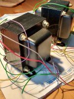
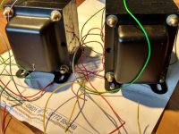
I've been wanting to build this amp that John Stewart shared with me a while back, and finally found (what I hope) are going to be some good output transformers. Antek has these MP-15W50 15W Output Transformer that are close to fitting the bill, and won't break the bank. If the amp serves me well, of course, I can buy more expensive iron later if I feel I need it.

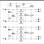
The design calls for a 4300K 43% UL tapped transformer to provide bootstrapping to the drivers to help overcome the trouble of massive drive signal needed by very low mu 6080 or 6AS7. There is also a way to do this without a UL transformer by adding a couple of extra resistors, which I have procured, but I'd like to do this with the UL transformer to save on the AC losses of using the resistors to provide bootstrapping. I'll post the schematic in a bit, it's something that jhstewart9 published in glass audio many years ago, and has graciously shared here too.

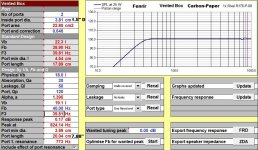
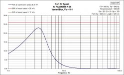
Because I'm a little bit cheap, and a whole lot curious, I also want to get a set of 50VA power toroids from antek to try as output transformers, as some have had success with power toroids as output transformers. Using two transformers, and putting all of the primaries in series will give 480V CT, with two 50% taps for UL/bootstrapping. The plan at the moment is to use transformers with two primaries and two secondaries to get somewhere around 4-6K into 4 ohms. I'm going with 4 ohms on the outputs, since the current speakers I'm using the most are nominal 4 ohms, and It's easier to add some windings to a toroid to get an 8 ohm tap, than it is to tear apart the insulation and remove windings. User kodabmx has reported having good luck using one primary from each transformer in series on each half of the center tap, in order to cross couple them, and reduce interwinding capacitance problems. I'm doing the maths as follows. Please correct me if I'm wrong!

Using the 115V/6V transformer AS-0506, they have a data sheet that shows the unloaded secondary voltage as 6.3V with 120V in. From there I calculate a turns ratio of about 38:1 (using 480V into 12V.6V), or impedance of 5800:4. This gives better distortion figures for most of the range, and may still net me close to the 12.5W out of clean power that John says he got from using a single 6080 with the hammond Iron. Using the 7V transformer I get about 4400:4

a pair of AN-0206 is even less expensive at $12, and two of those together weigh in about the same as the purpose wound 15W output transformer antek makes. The downside is the primaries are only good for about 100mA DC, so I may be on the verge of pushing them a little too hard. Only one way to find out!

The "upgrade" circuit uses two 6080 in parallel, which seems wise, IMHO not just for the extra headroom, but also since it will likely be easier to find two semi-matched tubes, when the two halves are paralleled. I've not tried checking any of these tubes in my pile to see if they are matched close enough or not, but others report that it is not too promising. Using AS-0509, I get 480 into 18.8 for the unloaded voltage and a turns ratio of 25.53:1, and impedance ratio of about 2610:4, which ought to be close enough for triodes 🙂 AS-1209 is the 100VA version, if this one proves to be inadequate.

Target operating point of the design is 250V with 50ma of plate current, or 250v with 100mA for the version with parallel tubes. I have three regulated supplies to run this from for construction and experimentation, and will worry about building the power supply once I've got working circuits. I've got some ideas about lowering the plate voltage a touch to help reduce distortion at the expense of output power. 210V at 60mA with 10W looks a little nicer, but I'll have to build to know! The load line simulator/calculator can only tell me so much without real world trials. The only issue is whether the output transformers will get unhappy with the extra bias current.

Dynaco SCA-35 PEC Modules

Does anyone have a Dynaco SCA-35 amplifier and can provide the dimensions of the two packaged electronic circuit (PEC) modules? These carry part numbers 555002 (for the tone controls) and 555003 (for the input loading). I want to make circuit boards to replace these; the assembly manual provides the schematics but I can't tell much about their physical size from the pictorial diagrams.

Thanks to anyone who can help.

kicker cxa 300.1 bad ps and outputs

hi everyone. working on a kicker cxa300.1, mp18021 replaced, irf3205 on ps and irf640 in the outputs, only for test, the amps works fine. now which is a good substitute for aot460 and aot412? i cant find on mouser and i dont use ebay cheap mosfet for outputs.

this is a 300rms little amp, im thinking the irf3205 works ok, more id and only 5v less on vds. but i dont 100% sure.

the aot412 are 60a and 100v, i have irfb4110 used on another bigger cxa at the ps, can i use it like output? these are 130a 100v more than twice the original part.

thankss

Lighter Note Hum/Balance Problems

Hi everyone,

I ordered a Lighter Note kit from Uriah a while ago and a few weeks later received, for reasons unknown to me, a readily assembled LN. It worked fine and I went on to use it with my ESP P101. However, I noticed after a while that in a certain range of the volume pot, there was a slight hum. I found out that it could be removed by connecting the 0V center tap of the 12-0-12V transformer to the ground plane of my PSU which is to connected to mains ground. I attached the cable permanently (I'd tried it by just holding it to the contact, and after that, the hum was gone but the sound was much, much quieter and the balance pot had stopped working. I removed the cable connecting the center tap to my star ground point again, but the sound remained quiet and instead, a new hum appeared. Its volume increases with increased volume pot settings (the one I had before would only appear from around 1/3 to 3/4 of the max volume setting) and it's much louder, except on the most quiet volume settings. The balance pot still doesn't do anything. I'm very confused as to what could be causing this, since everything is now set up the same way as before I started messing around with it, but the new problems remain. If anyone has any clues (or a schematic of the LN to give me at least some orientation of what might be wrong) what might be the problem, I'd be very grateful if they could help me out. I've also emailed Uriah, but have so far not received a response from him.

Speaker enclosure damping

I am trying to get enclosure damping straight, particularly fiber stuffing vs lining the internal walls with mat/foam sheets.

Here's what I think that I know so far:

Fiber stuffing performs the function of reflection damping and/or increasing the apparent size of the enclosure by up to 20%. This most often how sealed enclosures are treated.

Lining the internal walls with foam or mat fibers dampens internal reflections. This is the way many/most ported enclosures are treated.

Do I have this right? When, if ever would you use both?

Thanks,

George

Karlson's "Fig.6" Reflector - how large and where to focus?

I have an 18" Karlson type with curved upper panel which plays very nice.

Here's a little one with which could use some improvements (don't say pull its wings, etc. 😀)

The recording is analog and of John French so not the cleanest-most dynamic - thing in the first place.

A 10" driver K is about where the power starts. The slotted pipe tweeter can sound very good.


I would assume the focus of the reflector should be "outside" the aperture a bit.

Karlson Coupler with Eminence Delta Pro 8A speaker - YouTube

Looking for a software to simulate top mids and tweeters

Hi, is there any available program to design mid or tweeter horns?

I am interested in building top pieces to use them in a 2 or 3 way system. I am fond in building different bass enclosures with hornresp but i realized that using this program doesn't get me far with building tops. While you can get T/S parameters for midrange woofers i find it a bit odd to get low to no results for frequencies over 1khz.
Talking about tweeters you basically dont get any T/S parameters. I lack knowledge on this but my bet lies on insufficient acuracy in the tweeter range for those type of parameters. I really dont know honestly.

Is there any program that could work with only chamber resonances and wavefront simulations to get somewhat usable information on your chamber design? So instead of using an electromechanical approach i could try relying only on response characteristics of enclosures.

Afaik designing tweeters on hornresp bears no proper results.

SMT Soldering

I'm building a DIY DAC and had been dreading having to mount three 16 leg, SMT microchips (8 legs/side over 10mm). I decide to practice on a $7 Amazon kit. What a mess! Decided I've got nothing to lose; so I tried a technique I heard about. There were two 40 connector, square practice chips, 10 legs per 10 mm side. I soldered a couple of outer legs to keep the piece secure. Then I applied liquid flux liberally along one side then laid down a neat solder blob covering all ten legs. Let it set then, using my Hakko 630 de-soldering tool removed all the solder that wanted to come off. Perfect job: all legs connected, no solder bridges.

Probably everybody already knows about this; or someone will tell me why this is a bad idea because it fries the chip or something. If so, please advise. Thanks
  • Thank You
Reactions: PRR

Ultimate sounded Class D for diy without custom made IC's like Tripath TA2020

I note, that the most diy projects use only integrated solutions like follow pics:
http://www.6moons.com/audioreviews/kingrex/hero_tripath.jpg
http://www.russianelectronics.ru/files/14993/TPA3122D2-1.jpg
http://i62.servimg.com/u/f62/13/72/79/14/tpa10.jpg
http://www.irf.com/technical-info/images/tc-irs2092.jpg
High Performance Class-D Speaker / Headphone Amplifier Series | Audio ICs | ICs | ROHM CO., LTD.

but unfortunately no discrete ( I would better say "quasi discrete") solutions with Op-Amps and comparators I can find here with explicit analysing;

What is therefore the reason?
Is there no "Nelson Pass" or "John Curl" of Class-D designs (easy design, very high switching rate arround 10 MHz and good to understand circuit)?

Follow topology is more for beginners but not for top class requirements:
http://www.diyaudio.com/forums/class-d/159157-selfoscillating-class-d-amplifier.html

The topologies about this threads are good suited base for start own developement projects because the sound quality reach a certainly quality level:
http://www.diyaudio.com/forums/class-d/164460-newclassd-better-class-d-amp.html
(PDF pics about post #23)
http://www.diyaudio.com/forums/class-d/83244-lc-audio-zappulse-800xe.html
http://www.diyaudio.com/forums/class-d/158129-tc-electronics-switch-amp.html
http://www.audiopower.it/index.php?option=com_content&view=article&id=56&Itemid=53
and
L C Audio Technology / ZapPulse 800XE
but no detailled schematic diagram and circuit description is to be discover.

The only discrete schematic, that is to find here, is my own created from ICEPOWER, unfortunately not finished:
http://www.diyaudio.com/forums/clas...ic-about-rev-engin-not-complete-finished.html

4" Full Range Drivers?

Not too long ago, I picked up a pair of small li'l Optimus XTS 22 speakers with a 4" full range driver that sounds about as well as you think it would. Think AM radio in a 1972 Dodge Dart. I'm looking to replace them and am looking for suggestions that will cost no more than about $75.00 each. There's no crossover in these boxes, just wire straight from the connectors to the drivers. I have nothing against creating a crossover if that's necessary. I ain't afraid of no soldering iron.

Box size is 5 3/4" W x 4 1/2" D x 9 3/8" H

So far, the ones that seem most intriguing are:
Anyone have personal experience with any of them or anything else that you like? The application is near field listening at my computer, connected to a Fosi Audio BT20A amp running audio from my computer.

I'm not listening to Diana Krall or Brothers in Arms in an acoustically perfect room or anything, so some decent and cheapish drivers that I can slap into the Optimus boxes should suffice.

Ever Heard of an AudioQuest power conditioner causing problems with Thorens TD124?

I've restored a dozen or more TD124s. Recently I sold one to a guy and it instantly developed a problem. Before leaving my shop it was running very well: it came up to speed and stabilized in less than 5 minutes. He picked it up, so no shipping damage. When he got home and connected it, the speed was substantially slow - to the point that the eddy brake needed to be adjusted (i.e. couldn't be corrected with pitch control). Plus, when he dropped the needle, it slowed the table noticeably. I took it back and plugged it in to see if i could identify the problem. It worked perfectly right from the start. I was baffled until I learned that he was using an AudioQuest Niagra 1200 power conditioner. I have been on their website and can't really discern any facts about what it does. Just marketing hype and assorted blah, blah, blah. I'm curious to know what it might be doing to cause such a problem. The 124 is, of course, mostly dependent upon line frequency for speed control, but it will sag if voltage is quite low. I also wondered if maybe the guy had the power conditioner overloaded with other units (it's only rated for 15 amps) and not providing sufficient current.

If anyone has any thought, I'd be curious. I've taken the table back and will sell it again but am just curious. Cheers.

Are Tesla E88CC from eBay used, fakes, or just low price?

Lately i'm seeing lots of supposedly NOS Tesla E88CC's sold on eBay. Many are faked from Tesla PC88, ECC88, JJ E88CC, probably others too. The rest look like real silver pin Tesla E88CC with black shield, some are gold grid version. I find it strange such tubes used to cost around 50eur not long ago but now go for 20eur or so. Is some company faking new production by adding black shield, or prices went down because EH E88CC and some other new production tubes work so well?
I did pretty extensive tests with real NOS Tesla E88CC of two types vs EH E88CC showing new production are being made really well, they tend to sound very good and last years even at around max dissipation and voltages.

FS tube interstage transformer 1:1+1 for 5687 or AL3 triode

UK made, new design + production. New, not used.

2x interstage transformer for tube amplifier, ratio 1:1+1 for 5687 or AL4 / EL3N (in triode). Ip = 15 - 20 mA. Ip abs. mx = 25 mA. Asking price is 130 euros for two transformers (according to photo). Not for sale separately It seems US and UK might have customs difficulties. UK for sure.

This is the same company who designed and manufactured the 300B PP output transformers as published and sold once by World Audio Design.

IMG_20220224_113154065.jpg

Attachments

  • IMG_20220224_113205047_HDR.jpg
    IMG_20220224_113205047_HDR.jpg
    386.1 KB · Views: 101
  • IMG_20220224_113257720.jpg
    IMG_20220224_113257720.jpg
    263.5 KB · Views: 104
  • IMG_20220224_113214882_HDR.jpg
    IMG_20220224_113214882_HDR.jpg
    346.2 KB · Views: 108

B+ tapped after First filter cap and series inductor - electrical implications

Hello.

Where I come from guitar amps, and now getting ready to build a hi fi amp that's actually for an instrument that likes a more hi fi like presentation, I've noticed that many hi fi power supplies have the primary B+ tapped after a 1st filter cap and series inductor. I just was hoping for comments on this as it appears to hold a couple of positive benefits from my novice standpoint. It seems like you could both get a better filtered, regulated and thus more clean B+ while also, offering the opportunity to use a smaller 1st filter cap to help minimize in rush current. Although it may take a bit higher HT voltage to say, yield the power tube plate voltage desired, it seems worth it if other benefits are met.

Am I seeing this right on any level? As I'm wavering back and forth between whether to go SS or tube rectifier, the choice of PT specs naturally will change and those are critical.

Thank you!
Best,
Phil D

FS 3x MAG90X95 audio power MosFet = BUZ900P & BUZ905P in one housing

FS For Sale 3x MAG90X95 audio power mosfet device

The MAG90X95 is a power MosFet device with a Magnatec BUZ900P (N-channel) & a Magnatec BUZ905P (P-channel) in one housing.

Rare item. New. Unused.

Do send your offer.

Attachments

  • IMG_20220303_175314871.jpg
    IMG_20220303_175314871.jpg
    521 KB · Views: 120
  • IMG_20220303_175306249.jpg
    IMG_20220303_175306249.jpg
    598 KB · Views: 130
  • IMG_20220303_175253236_HDR.jpg
    IMG_20220303_175253236_HDR.jpg
    449.4 KB · Views: 157
  • Like
Reactions: wputera

Connect output grounds of isolated rail PSU?

Hi! need a powersupply for a MC-preamp. I already have a DC-supply like the one in the attached picture. I want to connect this to the 3045/3094 regulator in the next picture. I guess I would have to modify the DC-supply in some way to make this possible? Also, I need to get one more cable with the small, white connector in the picture. Anybody knows what they are called?

Attachments

  • bilde3.png
    bilde3.png
    82.6 KB · Views: 137
  • regulator.png
    regulator.png
    115.1 KB · Views: 138

Dual 10" in steel enclosure

Hey guys

I thought I'd share the dual 10" subwoofer enclosure I'm building for my 2 channel setup at home. It is being build from a 10-3/4" piece of schedule 80 steel pipe, this is because I absolutely hate everything about woodworking and I'm very good at working with steel. I'll be using a pair of Hertz Mille ML2500 drivers I've had kicking around for ages, I'll be powering them with a Behringer EPX2800 pro audio amplifier.

The large tube will be cut to accept the smaller tubes and they will be recessed so they only stick out about an inch. The excess material left on the inside will be cut off after everything is welded. I will be getting steel rings laser cut to mount the drivers to.

I will post up my blueprints tomorrow to give a better idea of exactly what I'm doing.

pxl_20220228_174350824-jpg.1030148


pxl_20220228_211857612-jpg.1030149

Attachments

  • PXL_20220228_174350824.jpg
    PXL_20220228_174350824.jpg
    590.9 KB · Views: 166
  • PXL_20220228_211857612.jpg
    PXL_20220228_211857612.jpg
    562 KB · Views: 171

For Sale Rega P5 Turntable for Repair or Parts

The problem with the Rega P5 is that the turntable speed does not sound as stable as it should. The RPM iPhone app shows that it runs close to 33RPM, but that the W&F measures 0.4-0.5%. I couldn’t find any published specs. I have decided to get a better turntable instead of chasing this problem and trying upgrades.
I am the original owner and have used the P5 sparingly over the past 10 years.
I also have the OEM box. Cartridge not included. Asking $500 + shipping.

Will sell individual parts if no one interested in the whole unit.
  • RB700 Tonearm with Incognito wiring upgrade
  • TTPSU
  • Glass Platter
  • Plastic cover

Attachments

  • P5 Front.jpg
    P5 Front.jpg
    116.2 KB · Views: 305
  • P5 Bottom.jpg
    P5 Bottom.jpg
    448.1 KB · Views: 341
  • P5 Box.jpg
    P5 Box.jpg
    285.8 KB · Views: 259

Mounting a Grayhill switch in a 10mm faceplate

I purchased an enclosure from the diyAudio store with a 10mm thick faceplate for the Kuartlotron I'm building. I purchased a Grayhill switch for the inputs but I didn't think this through when reviewing the drawing for the switch. The threads on the switch have a flat spot, clearly to stop any rotation of the switch body when selecting.

My plan is to drill a recess into the plate to mount the switch. My thought is to drill through the plate and file/Dremel away the mounting hole to size. I doubt it will be perfect, but taking it slowly, get a decent fit. If anyone know of a better option, let me know, as long as it doesn't involve expensive tooling for one switch installation.

Sony C37 Valve mic question

I'm having a go at building my first valve mic , and looking at various circuits. The Sony C37 appealed because of it's simplicity and offboard output transformer, but there is one aspect that intrigued me - it's a Cathode Follower design but there is no capacitor between the cathode and the output transformer so there is a fairly high DC on the transformer. All of the non CF designs I have seen have a large high voltage capacitor blocking DC from the plate , and all CF designs I see in amps and have used myself have capacitors too. Is there any downside to this ? I'm assuming it doesn't affect sound quality or the mic wouldn't be as revered as it is , but does it change the tolerance of the winding wire used?

Screen Shot 2022-03-02 at 14.17.33.pngScreen Shot 2022-03-02 at 14.17.46.png
  • Like
Reactions: krivium

Oscillations

After so many troubles with making and testing amplifiers with push pull buffers before the feedback point, I have decided to make a document which reflects what I have found.

An attempt has been made to make the document as concise as I can, just a few pages. Of course, the most important part is last.

The document concentrates, only, on simple weapons against oscillations, such as, a Zobel network and resistors. The new finding, which, I cannot find anywhere, is the possibility to eliminate or significantly decrease oscillations without any capacitors an Zobel networks, just, with simple resistors, which provide stable potentials and resistive paths for oscillations. The most important of them is a simple, load resistor in parallel to the speaker with a value of ten fold the value of the resistance of the speaker.

Of course, a combination of a few or all weapons against oscillations is possible.

Here is the document, called " Oscillations.doc " :

https://drive.google.com/drive/folders/1SXkcSbGwEz8DTH_6DdtDwolBuergbvyh
Projects by fanatics, for fanatics
Get answers and advice for everyone wanting to learn the art of audio.
Join the Community
507,743
Members
7,886,335
Messages

Filter

Forum Statistics

Threads
406,147
Messages
7,886,335
Members
507,743
Latest member
Fitodiod