Where is the star that created earth and our solar system?

Our earth is formed from and out of star dust which comes from a star exploding a long time ago.
If that is that case, then that star whichever it is must be still around in the form of either
a black hole of a white dwarf. But a star big enough to create our solar system, then most
likely it probably ended up being a black hole.

One possible explanation is cosmic inflation. If whichever star it was that exploded a long
time ago, through cosmic inflation, probably be millions of light year away from our solar system.

Our earth is about 4 billion years old. The universe is about 15 billion years old and inflation happens at
very early in the beginning of the universe. Which means that the star that created our solar system
must have explode very nearly early on before inflation and the space between the remnant (that created earth),
expand accordingly therefore it probably be very far away.

But if the star exploded much later on, then it must still be around close by.
Apartment Room Acoustics - panel placement and design

Hi Everyone,

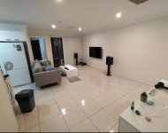
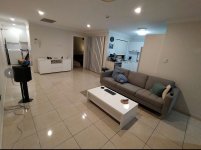
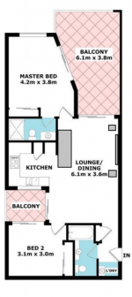
Who is up for the challenge of helping me tame this difficult apartment? What do I need to do to make this room sound bearable? My main issue is the lack of clarity with movie dialogue and music just sounds muddled in general.

Speakers are B&W 805s medium size (10 Litres) bookshelf speakers with front firing bass ports. No sub. Wall mounted TV

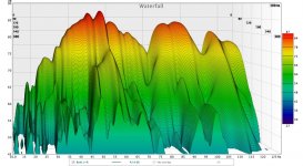
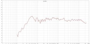
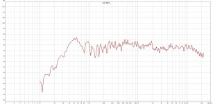
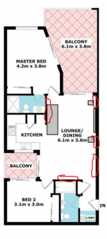
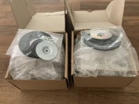
The attached photos and layout show the hard surfaces and complete lack of symmetry. Measurements of listening position and waterall plots attached.
1 . What type of treatments and thickness of panels do I need and where do prioritise placement of them?
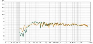
2. Do I plug the front ports of the speakers? I used some socks as an experiment and there is a drastic change in the measured base. It looks better with the ports blocked with socks, are there any other trade offs not shown in the frequency response chart?
3. Where can I get help or good resources. Will consider paying the right person for good advice.
4. Is a subwoofer needed (I only care about music though)
5. Do I need a rug?
6. Are panels on the ceiling worth considering?

My initial instinct is to get a bunch of artwork printed on canvas and stuff with rockwool or similar.

The below website recommends 16cm (6″) deep material with a weight of 40kg/m3 (2.5lb/cft).
https://www.acousticsinsider.com/best-insulation-material-diy-acoustic-absorbers/
That's some pretty chunky panels. Do I really need ones this deep? I'm just hifi listener not a recording studio.
Can I prioritise placement of deep panels and use ones 3" 8cm deep for the majority.

Thanks for your assistance!

Attachments

  • Room layout.png
    Room layout.png
    76.9 KB · Views: 206
  • Both L +R waterfall.jpg
    Both L +R waterfall.jpg
    250.7 KB · Views: 186
  • Both Channels 1-12 smooth.jpg
    Both Channels 1-12 smooth.jpg
    151.2 KB · Views: 167
  • Both Channels 1-24 smooth.jpg
    Both Channels 1-24 smooth.jpg
    161.6 KB · Views: 161
  • Sock vs no sock.jpg
    Sock vs no sock.jpg
    82.5 KB · Views: 199
  • picture 1.JPG
    picture 1.JPG
    369.7 KB · Views: 193
  • picture 2.JPG
    picture 2.JPG
    360.9 KB · Views: 194
  • Room layout with possible locations in red.png
    Room layout with possible locations in red.png
    77.9 KB · Views: 196

speaker stand/subwoofer

Good morning folks.First post and I am looking for advice on speaker stand and sub combo.
Speakers are Usher audio UA721 by Parts Express. 2 kevlar 7" mid woofers MTM design ,22" high x 9" wide. 4 ohm,38 hz bass response.
Room is 15 x 15 x 8 with 6' opening to kitchen.
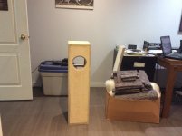
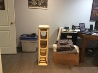
Thinking 9"w x 24" high ,depth depending on needed volume.2- 6.5"to 8"woofers forward facing,with plate amp.Around 30 hz would be great.80% music /20% HT
Building cabinets is not a problem for me.
Something like PMC TLE1 size wise would be about right. Too bad I can't afford them in cherry.
So my questions would be driver recommendations up to $125.00 each ,plate amp,and not sure if sealed or ported is better for me? And how to find cabinet volume /port size if applicable. I hope this is enough information.
Thank you, Scott

Seeking advice for a PA DSP speaker management or controller

Hello, I hope some of you out there know DSP crossovers for PA purposes that allow not only active x-over, EQ, delay, peak and RMS limiters, but advanced features such as excursion limiting and / or automatically raising a protective ("subsonic") high pass filter frequency depending on level, to avoid excessive excursion. Sort of a smart limiter that allows to maximize a woofer's (low distortion) output sacrificing some of its lowest frequency output where it can't reproduce the wanted SPL.

What can you recommend?

For Sale FS IanCanada 3.3V/5V LinearPi+UcConditioner+Ultracaps (several sets)

There has been a change in plan and I am selling a couple of these as complete sets.

All Ian Canada components are unused and come in the original antistatic bags and with original accessories. No solder on any of them. The ultracaps are Maxwell BCAP0350 E270 T11 - two in each set. They may previously have been mounted in an array and were subsequently removed from it. They are clean, unused and fully discharged.

There is one 3.3V set at US$162/EUR142 plus shipping. There are several 5V sets (US$154/EUR135 each plus shipping). If you buy more than one set you get a 5% discount.

Terms:

This is a private sale and there is no returning the items except if what you receive does not match the description given here in any way that is not insignificant. Location of the kit is Europe. You choose the shipping method. However, shipping must be insured and with tracking. Payment is by SEPA bank transfer or PayPal only

Sony CDP-XA50ES problems

its doing some things that i have not come across before, it needs to warm up a little before the logics work,once working it plays for any where from a min to hrs and it will stop and say there is no disc,
i have an idea that the servo pcb and the logics are one and the same,i will be changing out the 6 caps on this pcb, i have not worked with smd caps before so i will leave them alone for now ,so ill only do the elec type , i have not tested them off pcb but one 100uf is reading 600uf in place ,i hope this is the problem but doubt it,
what i would like to know is has any one worked on or had a similar set of problems that has been repaired in the past,
thanks
mike

Jeff Bagby's 'Quasi-Transmission Line loading'

I keep returning back to this article from Jeff which I am just enamoured by - what are the tricks for modelling your own version? I'm thinking about a smaller ~7litre cab based on the Purifi PTT4.0 and matching passive radiator.

https://www.facebook.com/groups/DIYLoudspeakerProjecPad/posts/815713518784487/

Helios Part 12 – Bass Alignment with Passive Radiator
The target for the Helios was a slightly larger than normal stand mounted monitor. The front baffle is just barely larger than the woofer is wide and just taller than the woofer and waveguide together are tall. The depth ended up being slightly deeper than the width of the SB29 passive radiator. So, there really isn’t a lot of excess size here. The internal volume is approximately 35 liters.
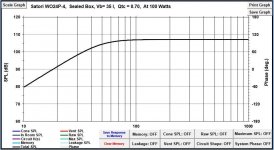
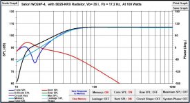
When working with a speaker this size with a larger woofer like the Satori WO24 the bass alignment becomes tricky. To compound the situation, the Qts of the woofer with wiring comes in at .42, and a Qts this high pushes up the required volume of the cabinet quite a bit from low Qts drivers. The 35 liters works out to sealed Qtc right at .7, which is maximally flat with the lowest F3 for a sealed alignment. Of course we might be able to get deeper bass from the speaker vented, but there’s two problems with that – First, the volume is too small for a bass alignment that does not possess some level of peaking. The peaking however, might not be considered objectionable by most people since it would be a broad smooth rise, but it’s still not flat. And second, the required port diameter for the WO24 would result in a port too long to work with this enclosure effectively.
This brings us to using a passive radiator. While it is possible to use a passive radiator to tune this enclosure to the optimum target of 25 Hz, there are still two issues that I didn’t like. First, there is still the hump in the midbass due to the small volume alignment, and second, the Fs of the radiator is higher resulting in a response that is dropping faster than 24 dB/oct below 40 Hz, despite this we have an F3 of 40 Hz and an F6 of 32. Also, with this alignment the cone is reaching an excursion of 17.5 mm at 20 Hz with 100 Watts of power.
My solution was to do something I came up with on the Testarossas that proved to be more successful than I expected. I called it at the time a Quasi-Transmission Line loading. I called it this because both the impedance curve and the box response curve were nearly identical to what you get with a heavily damped transmission line. This was accomplished by using a passive radiator that tunes the enclosure to a very low frequency, even below 20 Hz. The reason it worked really well on the Testarossa was because I found that this type of tuning worked miracles on controlling cone travel, and the MW16P woofers have a very compliant suspension and this additional control was a great benefit, as the cones stayed under control instead of bouncing around excessively.
Now, the more advanced guys are saying – But sealed will control the cone travel too by using the closed box air compliance to push back against the cone. True, but this passive radiator hybrid beats sealed. Here’s the comparison.
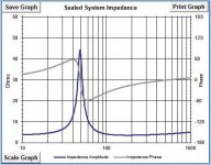
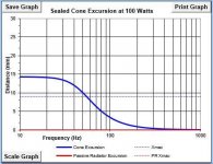
In the sealed box with the Qtc of .7 the system has an F6 of 36.7 Hz and an F10 28.0 Hz. Using our 100 watts of input power the driver excursion rises to 14 mm at about 20 Hz and below, against an Xmax of 9 mm. And typical to sealed systems with a Q of .7 the response is flat with a 12 dB/oct roll-off beginning at just below 50 Hz.
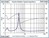
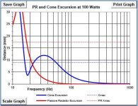
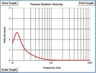
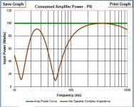
Using the SB29NRX-00 radiator right out of the box tunes the enclosure to 17.8 Hz. The cone response exactly follows that of the sealed system with a flat response with no peaking and a 12 dB/oct roll-off until we begin to approach the tuning frequency. The radiator output is not real high, but it does sum with the cone to produce an F6 of 33.5 Hz and an F10 of 25.4 Hz. System response is now rolling off at 8-9 dB/octave (you read that right) giving the system 4 dB more output at 20 Hz compared to sealed with no peaking. The more gradual roll-off matches very well with the rising room response of most rooms in this range yielding a system whose in-room response is very flat and extended to 30 Hz and below (for a stand mounted monitor just over one cubic foot in volume). Excursions? With the passive radiator and low tuning, the woofer’s excursions peak at 11.9 mm at 35 Hz with 100 Watts, but then below that begin to drop off to only 3.5mm at 17 Hz and doesn’t exceed Xmax again until 14 Hz and below. And for those wondering, Group Delay with this passive radiator and the low tuning is only 11 mSec at 20 Hz, which is very low as well.
Using the mass loaded passive radiator to control the cone motion of the woofer to very low frequencies not only adds a few dB of output in the deep bass, helping to extend it, and match the room curve better, it is also keeps the voice coil better centered in the gap to much higher power levels, resulting in even lower distortion from the woofer at low frequencies.
I attempted to make the Helios a very unique, near state of the art loudspeaker in the category of a stand mounted monitor, combining flat response, matched and controlled directivity, smooth extended bass, and low distortion – combined with fairly high output level. I wanted it to be as accurate of a reproducer as was possible to make using passive components, and I believe it will be tough to beat this one overall.


Thanks

Attachments

  • 58057671_578020832677351_3423586605657489408_n.jpg
    58057671_578020832677351_3423586605657489408_n.jpg
    56 KB · Views: 156
  • 57306006_578020812677353_8753046514915344384_n.jpg
    57306006_578020812677353_8753046514915344384_n.jpg
    28.9 KB · Views: 158
  • 57180239_578020819344019_7809472612647567360_n.jpg
    57180239_578020819344019_7809472612647567360_n.jpg
    27.7 KB · Views: 156
  • 57614992_578020766010691_6727248623374958592_n.jpg
    57614992_578020766010691_6727248623374958592_n.jpg
    29.7 KB · Views: 168
  • 57368805_578020779344023_4736819757452361728_n.jpg
    57368805_578020779344023_4736819757452361728_n.jpg
    31.2 KB · Views: 168
  • 57286205_578020772677357_5038974258663915520_n.jpg
    57286205_578020772677357_5038974258663915520_n.jpg
    63.1 KB · Views: 176
  • 57882625_578020719344029_478060586240835584_n.jpg
    57882625_578020719344029_478060586240835584_n.jpg
    22.7 KB · Views: 148
  • 57187563_578020722677362_5802316382410375168_n.jpg
    57187563_578020722677362_5802316382410375168_n.jpg
    26.3 KB · Views: 159
  • 57098966_578020709344030_5359150541433733120_n.jpg
    57098966_578020709344030_5359150541433733120_n.jpg
    26.5 KB · Views: 159

Advice needed for replacing tweeter in wharfedale diamond 8.2

Dear All.
I'm planning to turn my old wharfedale diamond 8.2 bookshelf to tower type. with active crossover. As those tweeter had been repaired for coil damage, I'm planning to change its original tweeter to something different like -

Option A-
Mcm Audio Select 53-1080 - 1" Soft Dome Tweeter
Impedance: - 8 ohm
Power Rating Nom: 30W
Sound Level SPL: 92dB
Frequency Response Min: 1.5kHz
Frequency Response Max: 20kHz
Power Rating Max: 60W , RMS 30W
https://in.element14.com/mcm-audio-select/53-1080/1-soft-dome-tweeter-30w-rms/dp/2827683
or Option B-
Doogesound DE17N-06 NEODYMIUM TWEETER
1) Material : Iron & Plastic
2) Sensitivity(1W/1M) : 89db
3) Nominal Impedance : 8 Ohms
4) Power Capacity : 15W RMS
5) Frequency Range : 1.4KHz-20KHz
6) Magnet Size : 30mm
7) Diaphragm Material : Thin Silk
8) Voice Coil Diameter : 35mm
9) Voice Coil Type : Round Aluminum Wire
10) Size : H/66mm, L/90mm
11) Mounting Hole Size : 60mm
12) Magnet Material : Neodymium N38
13) Frame Thickness : 3mm
https://www.doogesound.com/products/de17n-06-tweeter/692967000000017246
Above are the only specifications /details I could find. Imp parameters like resonance freq. , freq response at what +/-db are missing. My only reason for opting is that these are readily available in my area.

Please excuse me . I'm taking baby steps towards designing speakers , Please help me to decide between Ferrite vs neodymium, 26mm copper vs 35mm aluminum voice coils and 30W vs 15W power handling.

Thanks in advance,​

Attachments

Help with weird T/S parameters.

Hello everyone, I recently bought a Kruger Matz 15" km380t11 subwoofer I found its datasheet but things are strange at first I thought it was because everything is in Polish but soon I realize that some units are completely wrong or i think so.

These are the given parameters.

Revc: 3.4 Ohm
Fo: 29.025 Hz
Sd: 70.686 cm
Md: 200.410g
BL: 9.803 Tm
Qms: 5.798
Qes: 1.328
Qts: 1.081
No: 0.184%
SPLo: 84.7 dB
Vas: 103.609m M
Cms: 146.030u M/N
Krm:5.036 mOhm
Erm: 0.843
Mms: 205.893g
Mmd: 195.087m Kg
Kxm: 24.497mH
Exm: 0.649

so if someone is able to help me to understand what is going on i will greatly appreciate it thanks for you time.
I left the original pdf in the attachments.

Attachments

Sony FH-B7CD / KSS-240A problem (for Anatech)

Hi,

I just created a user ID hoping to get in touch with You (Anatech). I'm located in Mississauga, and I need help/advice from You.

I have an older Sony FH-B7CD mini component system, and my CD unit is acting up. It started skipping almost 10 years ago, and I bought a brand new KSS-240A pickup module, installed it and everything seemed fine again. However, not even 6 months later it started again.

I didn't want to bother with it again, so I bought a new system. The other day (10 years later) I decided to have another look inside, and I noticed a clicking noise coming from the pick up which is apparently caused by some gain control.

As I searched the internet for possible solutions this web site came up: http://www.diyaudio.com/forums/showthread.php?threadid=90009

It's a very nice unit, I like it a lot and would like to have it fixed rather than throw it away.

Can You help me please?

Robert

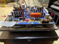
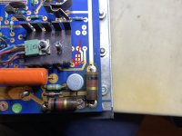
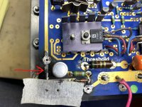
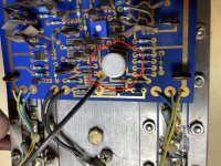
Need Help Identifying Black Wrapped Caps on Threshold 4000 FEB

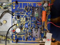
The 1K resistors on the FEB of my Threshold 4000 went up in smoke and did a nice job on the PC board while at it. I’ll be replacing the 4 resistors and also wanted to change a few of the caps while in there. Unfortunately, 3 of the 4 caps I want to replace are wrapped with a black Threshold label. I removed it hoping to find the values but no luck. I have 2 schematics for the 4000 but neither is a match to this FEB.

Looking at the “sort of close” schematics I have, I’m guessing the 2 smaller caps are 47 uF. They look to be on opposite sides of the schematic and the polarity is switched (I think). They measure .001 uF and 20.5 uF. I labeled what I thought was + and – on the board, but I’m not even sure of that.

The larger cap is labeled + on the board. It measures 400 uF. I’m thinking 470 uF?

There is a board number: Threshold 053-0308.

Anyone work on this particular Threshold 4000 FEB and have an idea of these 3 caps?


Thanks

Attachments

  • InkedIMG_4478_LI.jpg
    InkedIMG_4478_LI.jpg
    608.3 KB · Views: 172
  • InkedIMG_4479_LI.jpg
    InkedIMG_4479_LI.jpg
    525.5 KB · Views: 161
  • InkedIMG_4481_LI.jpg
    InkedIMG_4481_LI.jpg
    459.1 KB · Views: 159
  • InkedIMG_4482_LI.jpg
    InkedIMG_4482_LI.jpg
    343.3 KB · Views: 149
  • InkedIMG_4483_LI.jpg
    InkedIMG_4483_LI.jpg
    537.5 KB · Views: 150
  • InkedIMG_4484_LI.jpg
    InkedIMG_4484_LI.jpg
    580.9 KB · Views: 178

Exploring Visual Analyser (VA)

I've been exploring the 2012 Beta version of Visual Analyser (VA), freely available at Visual Analyser 2011 XE. It has some extraordinary features, but also a quite unusual approach. It would certainly be helpful to have a manual, tutorial or help notes while exploring. The author, Alfredo Accattatis, invites readers to contribute what he's calling Democratic Help. I've tried to contact Alfredo twice to offer my involvement, but no response so far (maybe he's on holidays!).

It occurred to me that at least some members of this forum might be interested in working together on developing the help, for all our benefit. For example, if one of us picked a topic and put together a tutorial on it, we could all try it out, throwing up objections and queries, and thrashing them out until we lost interest and declared it good enough. Then move on to the next topic until we have the thing at our mercy.

I'd be happy to kick off the first instalment, which logically would probably be on getting it working and initial exploration, unless someone else would like to do that one. I'd probably then move on to Calibration and THD, which I've already had success with.

Any interest?

Terry

  • Locked
Omnimic help please

Hello, im using this for the first time since 2017, i need help.
Im comparing my main speakers LCR, they are identical, so are their amps.

i want to over lay all their response curves, dunno where to start.

i have the 5.1 disc loaded, OmniMic setup and working on my computer and im running sweeps. I need to save sweeps then load em on the screen to compare them

Completed Mark Audio Pensil 10p

Hello Members,
I finally completed my Pensil 10p enclosures and have about 350 hours in them. Since this was my first build and my limited access to tools, I decided to used 4 window braces instead of the one suggested in the plans.I also went with a rear port instead of the front.
For the finish, I used walnut veneer for the sides, back and top and I used a flexible slate sheet for the front.I am really happy with the result and turned out better than I had expected.
I lined the top third,(sides,top and back) of the enclosure with felt and the rest with polyfill.
I like the sound so far but haven't started tweaking yet since I would like to wait until full break in(500 hours) before tweaking.
I am open to all tweaking suggestions from members who have experience with this enclosure and driver.

Attachments

  • IMG_0666.jpg
    IMG_0666.jpg
    416.4 KB · Views: 778
  • IMG_0668.jpg
    IMG_0668.jpg
    433.4 KB · Views: 752
  • IMG_0671.jpg
    IMG_0671.jpg
    419.9 KB · Views: 735
  • IMG_0672.jpg
    IMG_0672.jpg
    370.2 KB · Views: 776
  • IMG_0674.jpg
    IMG_0674.jpg
    364.1 KB · Views: 908

Impedance Question for the Experts

Not strictly DIY but I'm considering buying a non-functioning preamp to rebuild (Audible Illusions Modulus 3) with a 1.2Kohms output impedance. My favorite amp (rebuilt N.E.W. A20.1) has a 23.1Kohms input impedance. IN THEORY this is borderline, probably OK given the 19X difference between the pre's output impedance & amp's input impedance. I also called Audible Illusions and he was confident it's OK given the amount of current drive the Modulus 3 puts out. What are your thoughts/experiences here?

Thirlmere driver choices

Folks, just getting back to where I can resume building......
Wondering if the choices for drivers in the Thirlmere line are still the CHP-70.2? Or other drivers?
Plan is to build with foam and glued cardboard first. Would like to have the option of the second (rear driver) facing up.
And possibly the mouth facing rearward.

I see Madisound still has these drivers.

Regards,
Kevin
Red River Valley

For Sale FS: Alpha Core 12ga 3.3mH inductors

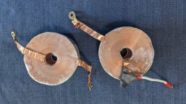
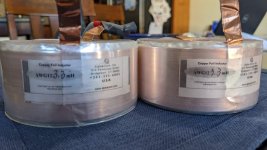
FS: pair Alpha Core 12ga, 3.3mH inductors

4" diameter, 2" height

Retail for $150 each ($300/pair) at Madisound ... asking $150 OBO for the pair.

Available for local pickup in Boulder, CO .. or will work with buyer to determine shipping. Together the pair weighs ~9.5 lb

https://www.madisoundspeakerstore.co...foil-inductor/

Goertz CF3.3 (12 AWG) Copper Foil Inductor (madisoundspeakerstore.com)

Attachments

  • PXL_20220308_163646493.jpg
    PXL_20220308_163646493.jpg
    661 KB · Views: 85
  • PXL_20220308_163730103.jpg
    PXL_20220308_163730103.jpg
    264.7 KB · Views: 82

Pioneer CS-77 Crossover mod update

Hi To All,
I wanted to give an update on my Pioneer CS-77 crossover mods that Steve Ponsford (aka. system7) suggested awhile back. I have attached a photo of the completed work. Try not to laugh to hard, this was my first time soldering on this level. Everything turned out great. My test album Dire Straits Brothers in Arms sounded very good. Bass is much improved and overall sound is much more detailed compared to the original crossover! This is an awesome forum with very helpful members. A special thanks to Steve for sharing his superior knowledge of crossover design with me.

Attachments

  • IMG_0164.jpg
    IMG_0164.jpg
    700.6 KB · Views: 1,103

Diamond Audio D9 800.4

Amp powers but has +35v on CH2 (Which is actually labeled CH4 on the front of the amp, but CH2 on the PCB).

CH2 output transistors are measuring OK but were driven to +35vDC on base and emitters. The PNP outputs have -35v on collectors. Removed outputs.

Used process of elimination to determine Q62 (2sc1845) had an open junction from E-B off the PCB. I replaced this part with MPSA42 installed with legs 2&3 flipped to match B-C-E on the board.

I then powered the amp up and the MPSA42 overheated within seconds and same E-B off the PCB opened. Voltage on Base of outputs went to -35vDC. Also Q70 which is a 2sC2682 shorted legs 1-3.


Im not sure if the MPSA42 was the cause or if there may be something else going on with this amp. All diodes, resistors, and caps are measuring OK.

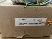
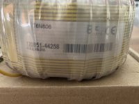
For Sale Menno VanderVeen toroidal power transformer 6N606

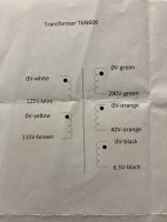
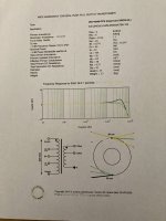
I have a Vanderveen power transformer that I ordered through Menno's website and manufactured by Trafco. Unused.
$50
2 x 115V primary
Secondaries
290V @ 600mA
6.3V @ 6.8A
50V @ 0.1A

Attachments

  • 6E11DEB8-0460-4712-8F93-390DA01F7216.jpeg
    6E11DEB8-0460-4712-8F93-390DA01F7216.jpeg
    390.6 KB · Views: 95
  • 80BE561C-DFEC-465F-94ED-93E1577146EE.jpeg
    80BE561C-DFEC-465F-94ED-93E1577146EE.jpeg
    314.7 KB · Views: 88
  • 1BD84931-3D06-4D9E-87E3-D7F637F38CE2.jpeg
    1BD84931-3D06-4D9E-87E3-D7F637F38CE2.jpeg
    477.4 KB · Views: 95
  • 9CA0E23D-BD0E-469D-A732-CE329F622D93_1_201_a.jpeg
    9CA0E23D-BD0E-469D-A732-CE329F622D93_1_201_a.jpeg
    490.6 KB · Views: 107

For Sale Menno Vanderveen toroidal output transformers

I have for sale a pair of Vanderveen output transformers. I ordered them through Menno's website and they were made by Trafco. They haven't been used.
Primary impedance 4K
Seconday impedance 0/4/8 ohm
https://www.mennovanderveen.nl/index.php/nl/producten/push-pull/vdv-4040-ppe-detail
$100 plus shipping for the pair.

Attachments

  • 33D10C86-6ACC-4263-97D9-8CC7A907A7ED.jpeg
    33D10C86-6ACC-4263-97D9-8CC7A907A7ED.jpeg
    421.6 KB · Views: 212
  • 0C32F9DE-CFDC-477C-85C6-AD890CE5D162_1_201_a.jpeg
    0C32F9DE-CFDC-477C-85C6-AD890CE5D162_1_201_a.jpeg
    427.1 KB · Views: 192
  • 884A280E-4D65-4CDA-A7C0-1B737CD51E37.jpeg
    884A280E-4D65-4CDA-A7C0-1B737CD51E37.jpeg
    397.3 KB · Views: 210

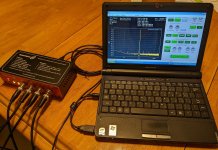
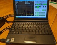
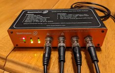
Testing setup, Quantasylum QA400 + Lenovo netbook

I have a great condition Quantasylum QA400 and Lenovo S10e netbook. This is a turn-key setup, ready to test as long as you have BNC input cables (the BNC cables in the pictures are not included). This does include the USB connection cable shown and several different versions of QA400 software as well as the electronic users manual. The laptop was recently fully reloaded with the original Win XP SP3 and the last version of QA software V1.23 is loaded. Other older versions are included in a QA400 folder along with the manual. The little Lenovo netbook has plenty of power for this task and is quite snappy for what it is. I used it as a stand alone test system, no network connections. You could set it up to attach to your wifi network but realize that you're pretty vulnerable if you start perusing the web with it. The netbook is small enough that this makes a good portable system. You do have to drag the Quantasylum control panel on the right side of the screen up/down with the mouse because the screen doesn't have enough vertical resolution for it to all fit. However you can start/stop the generator with the spacebar so its not necessary to always drag the control panel up or down.

A couple of things about the Lenovo. The CMOS battery is kaput, so it loses time/date if you leave it unplugged from the AC adapter for several weeks when you first start the laptop. You can leave it unplugged for days and this is not an issue, but for long periods it'll beep at you when you first start it. This is more of a nuisance than anything. I typically do not even set the time because I'm only using this thing as a test system. Also the main laptop battery is not holding enough of a charge to keep the laptop running for more than 30sec, so you'll have to run it on the supplied AC adapter.

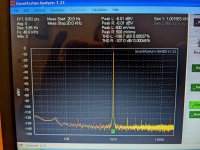
See the pictures of the QA running in loopback mode, so you can see the 1kHz performance of it.

Put a DIY attenuator in front of this setup and you have a nice system for testing a wide variety of gear.

NOTE, The BNC cables shown in the pictures are NOT included with this sale only the Lenovo + AC Adapter, QA400 & USB cable is included.

Price $175 + shipping. I accept paypal (you must pay 3% fee or send as a friend), or Zelle. Contact me via PM with your address for a quote on shipping.

Attachments

  • QA400_1A.jpg
    QA400_1A.jpg
    915 KB · Views: 157
  • QA400_1.jpg
    QA400_1.jpg
    897.3 KB · Views: 168
  • QA400_2.jpg
    QA400_2.jpg
    678.9 KB · Views: 159
  • QA400_3.jpg
    QA400_3.jpg
    671.5 KB · Views: 168

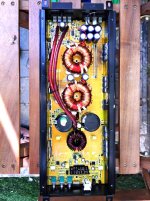
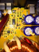
Sound Magus DK 1800 SMD transistor blown

hi,
Need help. Can anyone help me find the SMD part number of Q32 and Q33, as shown encircled red in the image of Sound MAgus DK1800 amp, They are blown as it is impossible for me to see the part number. Thanks a lot brothers in advance.

Attachments

  • Sound magus Dk1800 a.jpg
    Sound magus Dk1800 a.jpg
    521.8 KB · Views: 480
  • Sound Magus Dk1800 b.jpg
    Sound Magus Dk1800 b.jpg
    572.6 KB · Views: 431
  • Sound Magus Dk1800 c.jpg
    Sound Magus Dk1800 c.jpg
    476.1 KB · Views: 434

Introduction and request for advice

Greetings from sunny Lancashire (UK)!

After a bit of lurking I've finally joined up, initially for help on a project I need to build. This has also got me thinking that I would also like to learn more than just building a kit and would like to take it further.

My "pressing project" is a buffer preamp I need to build for my hifi system. I use a Streamer/DAC with variable output which goes into my modest power amplifier which has a lot more gain than I need. I have very efficient speakers (101dB @ 1 watt/meter) so currently have Rothwell 15db attenuators installed at the amp inputs. I've decided on the First Watt B1 design as it looks "quite" simple for a beginner project and would be ideal for my needs.

I'm primarily interested in solid state and would like to start by learning with simple mono, low power discrete circuits, which would hopefully build up some knowledge and experience before progressing to more ambitious projects.

Could anyone advise me of where to start, or point me in the direction of some good resources for a beginner (besides here of course!)?

I have a few bits and bobs to help me get me going:

Things I already have:

Fluke 77 MkII
basic hand tools
old Antex soldering iron
old USB DAC/ADC

Things I think I'll need to get first:

Decent temperature control soldering iron
Bench PSU
Prototype/breadboard
Small bookshelf speaker I woundn't be upset blowing up 😉

Is that a sensible list to get going or should I be looking at anything else from the start such as a function generator or scope?

Any advice gratefully received 🙂

Ian

For Sale FS: Hawthorne Audio Sterling Silver Duets (15" open baffle DIY) w/sub amps

DIY open baffle speakers featuring the Hawthorne Sterling Silver Iris 15" coaxial driver, Hawthorne 15" Augies for bass augmentation.
  • Augies are powered by 2 x 500W BASH amplifiers by O-Audio, these are mounting in matching oak-trimmed boxes which can be placed behind the Augies, or separately.
  • Baffles are a super-solid 3 inches thick (3 layers of 3/4" baltic birch plywood + oak trim). Each speaker measures approx 43" tall 23" wide x 20" deep
  • Crossovers are wired point-to-point, with decent components (massive Jantzen Wax Coil Copper foil inductors, Obbligato Gold caps, etc).
  • Bases contain the crossovers, are sand filled, and have spikes for leveling.
  • Grills included.
  • I'm the 2nd owner. Time to move these on to someone who will make use of them.
  • $650.
  • Available for local pickup in Boulder, CO. Willing to deliver within 100 miles of Boulder. May be willing to meet halfway for farther distance.

Product links with additional info:

15" Sterling Silver Iris driver w/crossover product info:
https://web.archive.org/web/2013041...?main_page=product_info&cPath=3&products_id=4

15" Augie driver product info:
https://web.archive.org/web/2013041...main_page=product_info&cPath=3&products_id=19

O Audio original product info:
https://web.archive.org/web/20080730092020/http://www.oaudio.com/500W_SUBAMP.html

Sterling Silver Duet review:
https://www.enjoythemusic.com/diy/1108/hawthorne_audio_sterling.htm

O Audio bash amp review:
https://www.audioasylum.com/reviews/Other/O-Audio/BASH-Subwoofer-Amplifier/tweaks/117881.html

Attachments

  • PXL_20220306_223223736~2.jpg
    PXL_20220306_223223736~2.jpg
    612.5 KB · Views: 431
  • PXL_20220306_223356912~2.jpg
    PXL_20220306_223356912~2.jpg
    500.3 KB · Views: 256
  • PXL_20220306_225137781~2.jpg
    PXL_20220306_225137781~2.jpg
    660.2 KB · Views: 365
  • PXL_20220306_225300068.jpg
    PXL_20220306_225300068.jpg
    293 KB · Views: 312
  • PXL_20220306_225425879.jpg
    PXL_20220306_225425879.jpg
    664.4 KB · Views: 258
  • PXL_20220306_225621887.jpg
    PXL_20220306_225621887.jpg
    379.6 KB · Views: 249
  • PXL_20220306_225630435.jpg
    PXL_20220306_225630435.jpg
    530.5 KB · Views: 247

Wanting to build a new preamp....what design?

I am getting the itch to build a new preamp. There is nothing really wrong with my current 124B common cathode resistive plate load preamp but I'd like to try something new.

My current setup is as follows

- Systemdek IIX (Rega RB330 arm) with Sumiko Songbird MC cartridge (0.5mV) ->
- Pass Pearl 2 phono (55dB 562Av) ->
- 124B common cathode preamp (22dB 14Av) ->
○ Pass FirstWatt F6 (input sensitivity 2.83V) ->
○ Anthony Gallo Subwoofer Amp ->
- Anthony Gallo Reference 3.1 speakers

Some of the things I'd like in a new preamp
- Low gain, based on my setup I need ~10Av of gain
- Low impedance output (input impedance of the F6 is 100K)
- Design that isn't super picky about PSU design

Because I just want to have fun building a new amp here are a few things I am going to try and incorporate 🙂
- Wood exterior chassis
- VU meters
- Input relay switching
- A volume control other than the Alps I've usually used


Thoughts on some design to look in to?
I was looking at the Akido/TubeCAD CCDA design, seemed intriguing.

Where do you get your replacement PCBs?

I have an Integra DTR 70.4 with no power. The relay coils are shorted, and the voltage across them are 5x what they should be.

Your thoughts?

I'm thinking an electrolytic went bad in the high heat Integra is notorious for.

I can try to fix the board, or just replace it, but I can't find it anywhere. Your wisdom is appreciated.

Thr to ignore the silicon job. It was that way when I bought it.

IMG_20220227_093132.jpg

Help with Personal Sound Amp project

Hi, I'm building a Personal Sound amp to hopefully relieve some of the issues regarding TV volume levels. I had a commercial unit before and it really helped the TV volume level stress issues!!

What I have on the drawing board is an electret mic feeding a transistor preamp, feeding another amp driving cheap headphones.

My questions:

In looking for circuit ideas for the amplifier following the mic preamp, would this amp be called a "voltage amp", an "audio amp", or "line amp". Keeping in mind the output is used to drive only the headphones (cheap ones at that) what type (name) of amp circuitry should I be looking for??

In the commercial rig I owned years ago, the mic was very near the TV with a long mic lead going to the amp near my "lazy boy" Is this ideal? Would it be better to have the mic and amp near the TV with a long lead for the headphones?

Thank you very much for your help!!

Power Supplies From Aliexpress

Has anyone used these "hifi" power supplies or of similar from Aliexpress? I am looking to power a 3 channel amplifier from TinySine. They are rated high from recent purchases, are these reliable power supplies?

Here are links
https://www.aliexpress.com/item/1005001986877034.html?spm=a2g0o.detail.1000023.13.1f5e1f98CEEiaahttps://www.aliexpress.com/item/100....store_pc_groupList.8148356.25.93ff3429jvhYmc
Is the 50W and PFC protection worth the extra $18

Also, is an EMI filter power switch necessary for an HIFI amplifier?

This is the EMI filter power switch
https://www.aliexpress.com/item/328...-1;4.04;-1;-1@salePrice;USD;search-mainSearch
I am in America so 110V input

This is the amp I purchased and will be using
https://www.tinyosshop.com/index.php?route=product/product&path=158&product_id=1092
I plan to do 3-way active monitor. Possibly running each channel at 4 ohm. Maybe running channel 3 at 2 ohm.

Other recommendations on PSU and other modifications are appreciated also.

FS - Various Drivers (RAAL, Scanspeak, Tone Tubby, 21" Sub) - Sydney, Australia

Items:
SOLD - 2x RAAL Dipole 140-15D-AM ribbon tweeter,
AVAILABLE - 2x Scanspeak 12MU/8731T00 4" midrange,
AVAILABLE - 2x Tone Tubby Alnico Red 8" Midbass,
AVAILABLE - 2x Pyle-Pro PDW21250 21" Subwoofer

Location: Sydney, Australia

Price (all prices in AUD):
Scanspeak $300 for pair,
Tone Tubby $400 for pair,
Pyle $400 for pair

Item Condition:
1x Scanspeak has cracked frame on two sides (measures and sounds fine),
1x Tone Tubby has ripped cardboard around front edge of frame (was attached to a ring using double-sided tape).
All other drivers in great condition.

Reason for selling: Disassembling open-baffle 4-way for sale.

Hi All,

These high-end drivers are fantastic performers and priced to go. They have been removed from their enclosures. As the drivers are heavy, I'd prefer to have the buyer pick them up.

Scanspeak - Quality little midrange. I dropped one of them, cracking the frame in two places, but the cone and surround are fine. It could be repaired, but even without repair, it should work perfectly fine when secured to a baffle. I ran them in a hanging configuration with the damaged driver and could not detect any degradation to sound quality or measurements.

Tone Tubby - This wonderful alnico magnet paper cone midbass is silky smooth. There's nothing out there that compares.

Pyle - I ran this 21" sub with 300W in a H-frame dipole configuration and it did not disappoint. It did require extensive EQ to work down low in this configuration (inherent to dipoles), so if you wish to use them in this way, you'll need a DSP. These are super heavy, so probably best for pickup sale only (Sydney, Australia).

Feel free to contact me for more photos or info.

Cheers,

James

Attachments

  • raal_front.jpg
    raal_front.jpg
    445 KB · Views: 697
  • raal_back.jpg
    raal_back.jpg
    580.1 KB · Views: 711
  • ss_front.jpg
    ss_front.jpg
    451.3 KB · Views: 683
  • ss_back.jpg
    ss_back.jpg
    377.8 KB · Views: 669
  • tt_front.jpg
    tt_front.jpg
    521.3 KB · Views: 666
  • tt_back.jpg
    tt_back.jpg
    557.5 KB · Views: 249
  • subfront.jpg
    subfront.jpg
    619.3 KB · Views: 244
  • subback.jpg
    subback.jpg
    406.1 KB · Views: 236

ACP+ Preamp/HPA for Yarra Preamp

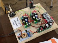
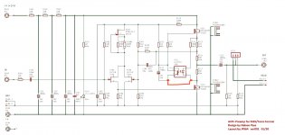
Vunce and I have both built the verification boards for the Pass ACP+ preamp / headphone amplifier in Yarra daughterboard format. This format also is compatible with the M2X amplifier front end bolt holes. Requires +24v supply and can be used as a standalone preamp/HPA.

850196d1591382163-acp-preamp-hpa-yarra-preamp-39b72e46-5acd-4973-891f-74e592e7a373-jpeg


The design is basically a miniature Aleph based output stage with a Aleph J or J2 front end (?). It sounds super and is very powerful with deep bass authority. A very nice sounding preamp that has tons of headroom. You will enjoy the sound immensely.

It is a mostly SMT layout in order to make it small enough to fit in the Yarra/M2X board format. However, the small tight layout contributes to an exceptionally low noise and great sounding design.

Thanks to Mr Pass for giving us the go-ahead to make this design for the Yarra/M2X. Thank you to JPS64 for another superb layout.

850191d1591381643-acp-preamp-hpa-yarra-preamp-a8615980-036f-4f9d-a6dc-e61b464e7678-jpeg


850192d1591381642-acp-preamp-hpa-yarra-preamp-5d51f614-0d4a-4d5d-891f-693e6136ca2e-jpeg


850193d1591381643-acp-preamp-hpa-yarra-preamp-4b5bb8a8-f385-4509-b706-233e3020cfd2-jpeg


850194d1591381643-acp-preamp-hpa-yarra-preamp-b7be5c1c-71ec-47f3-bc67-36247cc41fd4-jpeg


850195d1591381643-acp-preamp-hpa-yarra-preamp-9e98928d-b6a6-4d8d-ae46-b2ea5b252af9-jpeg


Please add your name, number of boards, and country to the interest list below if you would like to see a GB for this happen. Boards will be the usual price of $12 each and 1.6mm thick 1oz copper, ENIG finish. Green solder mask.

GB Interest List:
For example...
JohnDoe / 2 boards / USA

Edit Dec 24, 2020: BOM is here https://www.diyaudio.com/forums/attachment.php?attachmentid=904464&d=1608844039

Attachments

  • A8615980-036F-4F9D-A6DC-E61B464E7678.jpeg
    A8615980-036F-4F9D-A6DC-E61B464E7678.jpeg
    786.7 KB · Views: 1,736
  • 5D51F614-0D4A-4D5D-891F-693E6136CA2E.jpeg
    5D51F614-0D4A-4D5D-891F-693E6136CA2E.jpeg
    427.5 KB · Views: 1,906
  • 4B5BB8A8-F385-4509-B706-233E3020CFD2.jpeg
    4B5BB8A8-F385-4509-B706-233E3020CFD2.jpeg
    856 KB · Views: 1,754
  • B7BE5C1C-71EC-47F3-BC67-36247CC41FD4.jpeg
    B7BE5C1C-71EC-47F3-BC67-36247CC41FD4.jpeg
    786.2 KB · Views: 2,343
  • 9E98928D-B6A6-4D8D-AE46-B2EA5B252AF9.jpeg
    9E98928D-B6A6-4D8D-AE46-B2EA5B252AF9.jpeg
    814.5 KB · Views: 1,751
  • 39B72E46-5ACD-4973-891F-74E592E7A373.jpeg
    39B72E46-5ACD-4973-891F-74E592E7A373.jpeg
    173.1 KB · Views: 2,838

TDA7388 amplifier - is there a drop-in upgrade? (TDA7851 / Pioneer PA2030A ?)

Hi all,


Buying an Android head unit and specs shows TDA7388 chip, was hoping I could replace it with a TDA7851 or Pioneer PA2030A - or anything more up-to-date 🙂

But I'm not sure if these are drop-in equivalents or do I need to change other components on the pcb like different value resistors/caps to fit the new chip?


Thanks!

Now that I'm here, which way do I go?

Hello all. I'm Tim. Lifetime DIY'er, but relatively new to the forum.

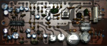
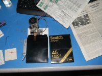
In the fall of last year, a friend tasked me with repairing a 70's vintage, odd-ball 8-track tape echo he was planning on using on an upcoming project. I had only found a few MENTIONS of it online; no luck in finding a schematic. It was an arduous task, as I was learning about tape recording tech as I worked the repair. In the end, my "If it ain't broke, don't fix it" leanings kept me from initially shotgunning the electrolytics, but that was the final fix, after signal tracing, replacing the vintage IC and a transistor or two, cleaning up a couple "mods" and fixing a few traces. Initial results can be heard here-> Login to view embedded media ME-8 Echo Layout trace overlay.jpg

This lead me to want to design and build an 8-track tape echo, with a long goal of building an all tube tape echo, spring reverb, harmonic tremolo unit. I've sourced NOS Nortronics heads and the appropriate QM kits. I've got a line on some NOS transport mechs, but I'm not holding out hope for that source. I do have a source for motors, should I have to design my own transport. With all that sorted or soon to be, that leaves me with circuit design, which is why I'm here.
DSCN3466.JPG

In the past, sourcing components was much easier. This often simplified the task of circuit design. The first hurdle for me will be figuring out the bias circuit for erase/record functions. Bias oscillators for tape machines aren't exactly easy to come-by these days.

What part of the forum should I look to direct questions about creating bias oscillator coils and associated circuits?

Thanks,
Tim

Greetings from a London flat

Hi all,

I just wanted to introduce myself. The reason I joined is I have mid-life project and this seemed the best place to document it and get some much-needed help!

I decided to buy a pair of Meridian M30 active 'speakers and learn as much as possible about them, fixing and upgrading on the way. I'm a software engineer by training, manager by profession and haven't done any electronics since A-level physics.

I'm hoping to use this as an "interactive log book" where I document the project as I go along and hopefully people will chime in with thoughts and assistance as we go.

As they are active speakers I'm not sure whether to document under amplifiers or loudspeakers!?

Anyway, hopefully it should be fun.

All the best
Ian

🟢Audition room, golden ratio. What do we really know?

Hello everyone! I'm opening a thread because I couldn't find a related topic on the forum.
In view of the planned construction of a new room, I remembered the acoustic "controversy" of the golden ratio.
If anyone wants to vent about it, feel free!
vou deixar alguns links relacionados.

Extraído de:
In mathematics, if two numbers have the same ratio as the ratio of their sum to the larger of the two numbers, they’re said to be in the “golden ratio.” If that sounds like Greek, don’t worry. The “golden ratio” in sound – more specifically in acoustics, doesn’t require you to understand the mathematical term and all its implications.

Instead, this ratio is related to set of ratios that tend to lead to the best acoustic response in a room, with a minimum of acoustic interference anomalies such as comb filtering, nodes, peaks, or dips. Knowing these ratios can help you to look for the best room in a house to put your studio or rehearsal space and are especially useful if you’re building a new space and can control the dimensions of the room

01- Em https://hexspa.com/golden-ratio-acoustics/

golden.jpeg

Reclocking Tutorial

I need to know more about what clocks are purposely used for streaming , cd's and other uses . For instance ,can a 6Mhz be used for cd's at 44.1 khz? I know 5.6Mhz is the proper clock . Just trying to understand what's going to work and not using streaming at 192 Khz which I know is at 24.5760. If I just go with a higher number will it play? 10Mhz is used for the uptone regen, could that work for using cd's?

Aleph 2 Monoblocks

I went for a walk on the web and a pair of DIY Aleph 2 monoblocks followed me home. It was like I fell into a mid ‘90’s time machine.

They were originally built by a builder we all seem to know, using the Brian GT boards. Of course, one mono worked and the other did not. I tried the one that worked and it played music without much enthusiasm or substance.

I got a new pair of the Brian GT boards from a generous diyaudio member but they seemed a bit kludgy and I felt there might be better options. I also found PCBs on various sites but they all seemed a bit suspect.

With a bit of luck and a touch of persuading, I convinced rhthatcher (longtime leader of having a certain type of amp follow him home for repairs and updates) to create 2 sets of Aleph 2 Front end boards and daughter boards. Randy also provided me with the matched mosfets, matched 313s and answered many of my texts and emails as I figured things out and worked through the usual start up issues. A true Diyaudio member and gentleman.

I disassembled the non-working amp down to the chassis. I think I only kept the donut, switch and jacks, (for the moment). I got proficient at drilling and tapping 3mm threaded holes for the 24 mosfets that the two chassis use. I made a rookie builder mistake when I could not get my dimbulb tester to dim when I fired up the first amp. It turned out that my 150 watt bulb was not going to dim when your amp sucks down 300 watts. Once #1 was finished, #2 went much quicker except for that cold solder joint on the power supply.

My goal was to build a pair of amps for my vintage ADS 910 speakers. 6 ohm and not Maggies but not the easiest, either. I figured the Aleph 2 would pair nicely with the 910s. Plus, it would be nice to give a bit of love to the Aleph line and get these orphans working and set up properly.

How do they sound? First weekend impressions- they are authoritative. Neutral in color, not sweet or dry with my B1R2. Bass and pace are strong. They wake up the speakers in a way I haven’t heard them before. I’m guessing this is what the speakers must have sounded like to the ADS crew during the Design process.

Many thanks to Papa for his skill, support and generosity! And of course thanks to Randy for his skill, knowledge and patience supporting my windmill tilting Aleph 2 quest!

Attachments

  • IMG-3919.jpg
    IMG-3919.jpg
    1,018.2 KB · Views: 378
  • IMG-3920.jpg
    IMG-3920.jpg
    917.6 KB · Views: 371
  • IMG-3936.jpg
    IMG-3936.jpg
    1,021.8 KB · Views: 386
  • IMG-3941.jpg
    IMG-3941.jpg
    1,012.3 KB · Views: 375
  • IMG-3942.jpg
    IMG-3942.jpg
    756.4 KB · Views: 377
  • IMG-3972.jpg
    IMG-3972.jpg
    1 MB · Views: 333

System 18 Ram 1500

To my understanding in this truck the (3) 3 1/2" dash speakers are wired in parallel with the front 6x9s in the door, I have the Alpine ilx-w650 receiver 6x9s in the rear doors all speakers are MB QUART and I have the alpine BBX-F1200 4ch amp. The front door speakers sound like crap and so do the dash speakers I was told to use bass blockers where would I put them and what will this do. Please advise

Diagnosing and fixing amplifier fault (loud crackling and popping)

Hi,

I've got an amp here for repair, which produces loud crackling and popping in the right channel, ocasionally. It has been doing this for years (5 or perhaps even more) sometimes, but it is getting worse now. I've already determined the fault exists somewhere in the poweramp, right side (left and right are on seperate PCB's).

I know this can be caused by degrading electrolytic capacitors, but tests would seem to indicate that this is not the cause.

My main question is: can transistors, and perhaps MOSFETs, be damaged in such a way that they will sometimes short or go open?

Also, perhaps somebody has other suggestions as to what it could be?

Kicker ZX700.5 Protect Transistor substitution

Hi All,

I am repairing a ZX700.5 and the only fault I can find is Q315, that is short. The original is KTC3875GR and I would love to get some recommendations for a substitute. My first preference would be 2SC1632, even though the IC is lower (which looking at the circuit should not be an issue) and the VCE(sat) is slightly higher also. I attached the data sheets for reference.

Thanks all!

Transistor VCEO IC hFE VCE(sat)
KTC3875 50V 0.15A 200-400 Max 0.25V
2SC1623 50V 0.1A 300-400 Max 0.30V
MMBTA06L 80V 0.5A Min 100 Max 0.25V

Attachments

Combining EF and CFP output stage

Hi Guys,
I am interested in designing an output stage to mitigate some of the high frequency crossover issues with the CFP topology. I have heard some mention of combining the CFP in parallel with an emitter follower stage.

Has anyone here used this in an amplifier before, how did you bias each pair of transistors and where there problems with one pair doing all of the work.
What are the best practices for designing with this stage?

I don't really know what I am doing but after some trial and error this is the general concept that I came up with.

cfp and ef output stage.png


I am hoping that this thread will lead to some interesting discussion, and if this has been talked about somewhere before please let me know.

Alex

Peak Voltage Detector

I was planning to use the peak detector described on the Elliot Sounds website:
https://sound-au.com/appnotes/an014.htmSpecifically this one:

an014-f3.gif

However while simulating its response I noticed the maximum peak is limited by VCC/2, can anyone explain this to me?
The circuit in figure 2 is also showing as limited to VCC/2.

How could I alter this circuit to alter this response?
I have +/-5V and I'd like the peak detector to work from 20mV to 3V3 (3V is also acceptable).

I've also tried https://www.analog.com/en/technical-articles/ltc6244-high-speed-peak-detector.html but it is unable to monitor low voltages.

Resizing an image moves the page scroll

When I insert an image into a post, resizing using the image handle results in the web page scroll bar moving also.

To test:

Raise a new thread,
Insert an image,
Click off the image then click the image to get the resizing handles,
Grab the bottom right resizing handle with the mouse and drag,
-What I see is the web page scroll bar on the right hand side of the screen moves with the mouse motion.

Windows 10, Chrome, Logged in, Incognito and normal.
Projects by fanatics, for fanatics
Get answers and advice for everyone wanting to learn the art of audio.
Join the Community
507,738
Members
7,886,221
Messages

Filter

Forum Statistics

Threads
406,143
Messages
7,886,221
Members
507,738
Latest member
Tatsuyadono