8 Pieces NOS -- 2N3790 Transistor GP BJT PNP 80V 10A -- TEXAS Instruments

$40 shipped or best offer for the 8 -- 2N3790 Transistors.

I have a lot of vintage transistors, most are new old stock.

2N3055 (about 5-6) couldn't upload, too many pics.

Attachments

  • 20210520_144045.jpg
    20210520_144045.jpg
    1.1 MB · Views: 184
  • 20210520_144317.jpg
    20210520_144317.jpg
    1.1 MB · Views: 221
  • 20210520_144344.jpg
    20210520_144344.jpg
    1.1 MB · Views: 172
  • 20210520_144450.jpg
    20210520_144450.jpg
    1 MB · Views: 174
  • 20210520_144525.jpg
    20210520_144525.jpg
    1 MB · Views: 158
  • 20210520_144551.jpg
    20210520_144551.jpg
    1 MB · Views: 130
  • 20210520_144610.jpg
    20210520_144610.jpg
    1 MB · Views: 120
  • 20210520_144628.jpg
    20210520_144628.jpg
    1 MB · Views: 124
  • 20210520_144654.jpg
    20210520_144654.jpg
    713.3 KB · Views: 119
  • 20210520_144725.jpg
    20210520_144725.jpg
    989.1 KB · Views: 135

Basic Q again: External PSU (CRC) …

Hi friends
Now that I slowly seem to get back into „think DIYA“), it all reappears:

If (big if) I was to pluck my F4‘s PSU into a separate chassis, feeding the 24VDC through an umbilical, this wire would be the second R, which had to be followed by a third bank of caps (bugatti/moto guzzi etc), I‘d then had a CRCRC right? And thus, the cable's quality (length, diameter) is of some importance, right again?
Thank you

From 8.5mv of hum to 330mv .... oops.

I've been messing around with a giant two-chassis 845 SE amp based on Grover Gardner's circuit. It worked o.k. as I initially built it, but didn't sound as good as I wanted and 8.5mv hum was too much for me. Unfortunately, my extensive mods are giving me about 40x the hum I had before!

I went from a single filament supply for all the tubes (845s, 6l6s, and a 6n7) to separate supplies for each 845 and one for the 6.3V tubes (the single supply was a relic of the way I bought the project--not by choice). The 845 supplies now use separate secondaries from a big old Hammond 1143X (thanks, Ebay!) running into full bridges of shottkys, then CRCRC followed by a common mode choke. The center taps of the secondaries are tied off. The negative leg of each 845 socket connects to a 100 ohm resistor to ground (test points on each side for biasing). Between the legs of each 10v supply (at the socket), I'm getting 1.1mv or so of ripple. But, I'm getting like 2.5V of ripple across the 100 ohm resistor?

I get that same result on the 100r resistor with or without the B+ on. When I connect the B+, it shows 1-2mv of ripple where connected to the OPT primary, but then 12VAC at the 845 plate? Bias supply shows 1-2mv of ripple. (All just according to my DMM).

I'm assuming I'm not understanding something about how I built these filament supplies. But, for context, the other changes I made include adding PS capacitance (not excessive and same first cap--the reservoirs were probably too small before), separating the signal and chassis grounds in a larger umbilical (they were joined in the signal chassis for lack of wires before, they are connected in the PS chassis), and connecting the speaker ground to signal ground with big 100 ohm resistors (they floated before). The 6.3V supply is also DC from its own transformer, but less filtering and with the negative at signal ground.

Thanks for any help!

Paul

Am I Leaving Class A Yet...???

So I have read the articles and still want to run this by people to determine at what wattage i'm into class AB. I have a F5t V2 actually maybe 2.5. I'm using cascode on the front end. My output stage consists of two pair per channel. So 4 trannies per channel. The rails are running at 50volts +/-. I'm clipping right at 123 W/ch. Each trannie is biased to .8 amp. So from what I understand im in class AB when I reach 2X idling current. Is that based on total current per channel. 2X=3.2 amp? Or 2x=6.4A. Can someone explain please.

Somethings wrong with my spkr….help

Not sure if this is a good place to post this question….

my one main speaker is exhibiting a dip in its response. My mains are three identical center channel WTMW designs. Their XO is 400hz/1.8khz. The red line represents the other two speakers, the dip is the speaker that sounds off. What could cause this speaker driver(s), XO parts, solder joint. They are at least 15 yrs old
1646787350674.jpeg

1646787735957.jpeg

Help request: any Chinese members willing to help?

There is a Chinese hi fi dealer who has an item I am interested in, but I am unable to send him a message of any kind as there is no email address shown on the website (as far as i can tell) - there is a WeChat number (i don’t have that and its difficult to get in the West) and a phone number.

I need someone with WeChat to send a message and ask for the email address.

Please PM me if you are willing to help.

Analog VU meter in power amplifier

Hi,
I have the big VU meter panel from a scrapped Uher Reference No1 power amp (meters were originally driven by the Toshiba TA7318P IC) now I want to use these VU meters with the PeeCeeBee V4H power amp that I am building, I don't want a true VU meter function but just a nice bouncing for visual pleasure, I wonder if this is a suitable driver for my project NEW upgraded edition OF TA7318P VU Meter Driver PCB Board Stereo module | eBay


An externally hosted image should be here but it was not working when we last tested it.

VFET with help from an F4

I know I'm not reinventing the wheel here.

Today, I ran my VFET with some old '70s vintage, 3 way, inefficient, floorstanders. It sounded great of course, but it needed a little oomph to get to some listening by myself volume.

The other day I reread the First Watt F4 manual and remembered that in addition to being a great sounding amp, it's a power buffer and should be able to help the VFET with it's oomph issue.

I got the F4 out of the garage and hacked off the end of an old RCA cable. I added two banana plugs to the end of the cable and plugged them into the L/R positive terminals of the VFET with the RCA end to the input of the F4. The signal went- preamp/VFET/F4/speakers.

I checked my connections and crossed my fingers. These days I usually don't let the magic smoke out but mostly get the sound of silence, followed by a lot of cursing. I'll be dammed. It worked and sounded much better than expected. (Which is my usual feeling when I finally get my Papa projects to work.)

Anyone else using their F4 as a compliment to their VFET? Do you have a better way of connecting the signal between the VFET and F4?

Attachments

  • Vfet-F4.jpg
    Vfet-F4.jpg
    647.3 KB · Views: 171

Racam (round aca monoblock) pcb's for sale uk only

Hi folks having ordered some of the RACAM ( round ACA Monobloc) pcb's (delivered to me in around 14 days from the date on this post) through Mark Johnson I have some spares, x4 pairs I only want what I paid for them plus say £3 1st class postage to MAINLAND UK only.

See thread and links here - https://www.diyaudio.com/community/...acam-round-aca-monoblock.384057/#post-6968808

So £13 per pair of pcb's plus £3 postage

Buffalo III upgraded with ES9028Pro

Since I happened to have a burned out Buffalo III board, I experimented with mounting an ES9028Pro on it.

ES9028_2.jpg


Since the 9028 has the same pinout as the 9018, all that needs to change on the B3 board is:

1) Put a jumper on the reset pins.
2) Put in a higher current supply for the 1.2V PS. I found that with a 100MHz clock and 352.8K material current consumption is around 200mA.

ES9028_3.jpg


I also made a new set of Trident replacement power supplies:

ES9028_5.jpg


It turns out the I'll have to do a new design for the 1.2V power supply, since it's running pretty hot right now..

The experiment was a success. I'm controlling it with a piece of experimental code running on an Arduino and the sound is a substantial improvement over the "stock" B3.

attachment.php


Next step is doing a new version of my TFT HiFiDuino code that is compatible with the 9028/9038 (their digital core is exactly the same, my code has been tested on both of them and works fine).

I've posted a couple of more detailed posts on the subject on my blog, if you'd like to read "the long version" of the experiment:

Yes, I put an ES9028Pro on my Buffalo III | Dimdim's Blog
ES9028Pro power wows | Dimdim's Blog

PS. If you happen to have a Buffalo II/III/IIISE that has an old AVCC shunt regulator on it, change it for a new Trident SR or other hi-end LDO reg design ASAP. You will get a substantial SQ upgrade for very little money.

Attachments

  • ES9028_3.png
    ES9028_3.png
    22.6 KB · Views: 3,168

Soundstream Reference 200S modification experiment

Experimentation only

Im trying to go where no man has gone before - that is mess around with an old Soundstream Reference 200S amp. I've re-wound the transformer for twice the rail voltage. Amp now runs +-44vDC rail whereas before it was only +-22. For regulated voltage, I replaced the 16v zeners with 18v units and now the regulated circuit runs about +-18.5vDC (Which helped boost clipping point on the pre-amp). I know the opamps are going to clip while and always, where +-18vDC did help lift the point of clip, but not enough for the rest of the amp. I cant get the clipping point to come up much further on the output though. The regulated/opamp outputs will clip before the amplifier drive and output circuit.

Been looking at the 300/300S schematic so the following is in reference to that amp.

I tried fiddling with the voltage divider after UC1 (Pin 8) at R42 and R43 which on this amp was a 620/1.2k set, to 47/4.7k and that helped a little - but not by much. Would I need to modify R2 and R3 instead? I believe those are on the driver cards.

Experimentation only

2465 Tek Scope NO Display, Suspect the A9 PCA

Retired and enjoying it, I decided to repair my 2465 scope that died about 4 years ago. It didn't get much use. Before dumping it {didn't have the heart} I revisited the fault because I now have the time.
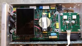
Fault: NO Display and passes the power on tests and front panel leds are correct. A9 Q1981??? gets very hot and the -15v is 4v.
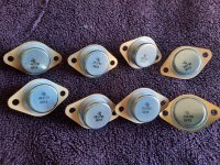
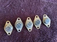
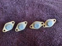
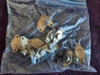
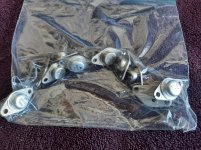
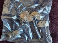
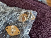
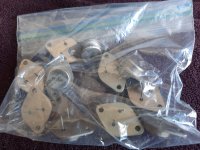
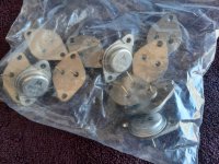
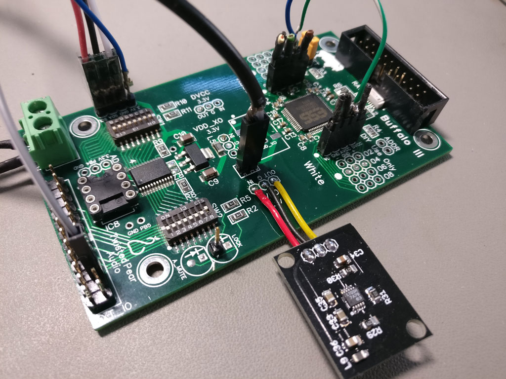
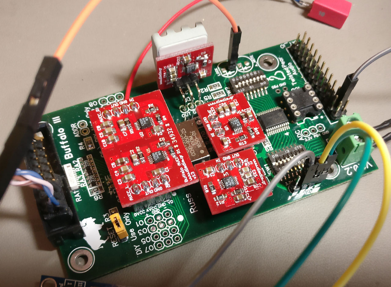
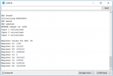
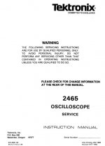
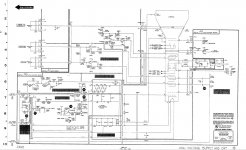
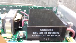
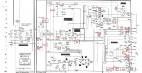
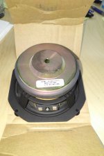
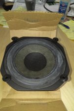
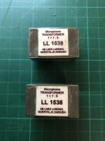
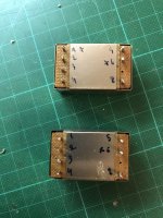
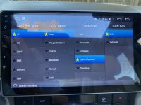
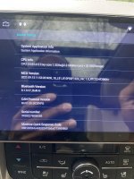
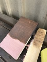
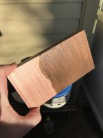
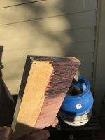
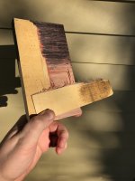
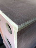
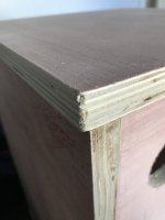
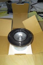
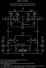
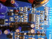
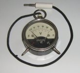
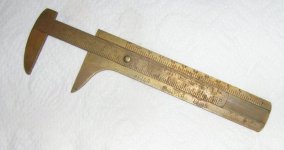
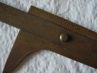
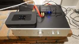
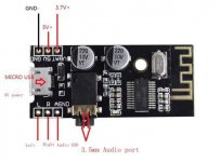
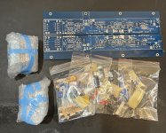
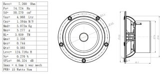
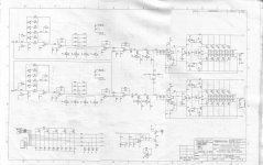
I downloaded a 2465 service manual {Image 1} and started diagnosing, the first thing I noticed was that the A9 PCA layout and schematic was not like mine {Image 2 & 3} Close but not good enough, hence the ???. Now for the sad bit, I can't find the back panel and therefore don't know the serial number. The A9 is part number 670-7277-07 {Image 4}
Moving on I disconnected pin 7 of the HV multiplier U1803 and the -15 was now o/k and no over heating of Q1981.
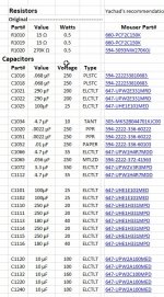
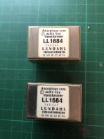
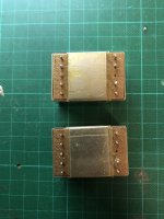
I have downloaded PCA layouts & Schematics for a nunber of 2465A,B and they seem to use the same A9 152-0805-00 {Image 5} therefore assuming this I continued.
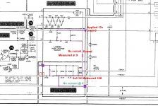
Applying 12v to pin 3 of U1830 to pin 9 there was no current flowing, even forward biasing the high voltages internal diodes.{Image 6}
In my opinion I suspect U1830. Why it causes Q1981 to overheat i don't know, I was looking for a short or maybe T1970 is not oscillating, I need a scope.
Checked all the voltages and are close to those indicated in the schematics. Measured both low and high value resistors and are all within 5%. pin 7 is still disconnected.
Checked the CRT pins to ground and all infinity resistance. The DMM is old like me, never been calibrated.
Checked the electrolytic caps the best i can but will not change components without a good reason, you know the saying.
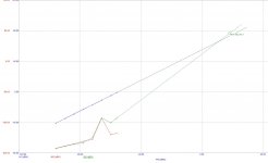
Thanks to Yachad's excel spreadsheet I found when surfing, I have marked all the caps that require changing if needed. {Image 7} {Image 8}

Any suggestions or any questions as to what I have left out let me know?

How would I go about getting the correct manual without a serial number? Would a particular PCA part number help?

Thanks
gazza

Attachments

  • Image 1.jpg
    Image 1.jpg
    49.4 KB · Views: 95
  • Image 2.jpg
    Image 2.jpg
    392.7 KB · Views: 100
  • Image 3.jpg
    Image 3.jpg
    222.3 KB · Views: 108
  • Image 4.jpg
    Image 4.jpg
    257 KB · Views: 103
  • Image 5.jpg
    Image 5.jpg
    264.7 KB · Views: 95
  • Image 6.jpg
    Image 6.jpg
    190.1 KB · Views: 91
  • Image 7.jpg
    Image 7.jpg
    313.1 KB · Views: 96
  • Image 8.jpg
    Image 8.jpg
    134.5 KB · Views: 98

PS Audio power Regenerator "smoke testing" after rebuild

I just recently decided to attempt a rebuild on a PS Audio Premier "Power Plant regenerator" based on the some what vague service information provided by PS Audio. The rebuild includes replacing multiple surface mount components on the regulator board and the four darlington power transistors. I decided to replace all the electrolytic capacitors as well just.

I am now at the "smoke testing" stages where I disconnected the regulator and ran the unit on a 250W dimbulb. Everything appeared okay and there was not much current draw from the unit.

Now this is where my concern is since I don't want to blow up $75 worth of transistors so I kept in on the dimbulb. When I hook up power to the large rectifier on the heatsink that drives the darlington regulators the dimbulb goes to full brightness and does not dim down.

What should I do now? I have no schematic to work with so I am hoping I can find some one who has experience working on these units and since I got this for "free" all I have to lose at this point are the parts I threw into it but would prefer not to blow up the new transistors if possible. 🙄

TA-5650 Repair for 2022

I've got my hands on a TA-5650 with known issue of blowing the rectifier board fuses on power-up.

It appears to be unmolested other than the relay looks to have been tampered with and bunch of soldering on the wire wraps between the rectifier, power and amp boards. My plan is to pull the V-Fet's and unhook the power leads between the rectifier & power board to the amplifier board. Then, check the condition of the power board and rectifier board to specifications with the amplifier board safe from defects in the rectifier and power boards.

That said, any advice from someone that's worked on one of these as know causes of blowing both fuses (they might have just powered it up after years of not using)? Any ideas on identifying what would cause both fuses to blow or approaching fixing root cause?

Hemp Acoustics MB6.5DIYNR Mid Bass

SOLD : Since the tweeters received offers faster than expected, it is time to advertise the mid bass drivers I selected.

I am giving up the dream of build my own home theater speakers. Just will not be able to find the time.

I have 10 of these for sale, brand new only taken out of the packaging to take the picture.

Dug through the archives and dusted off the data sheet for these. See 5th picture.

The plan was to put a pair in 16 l closed box enclosure to get the responses in the 3rd and 4th pictures. The design was to get a maximum of about106 dB from each driver set. Not that I'd listen to anything that loud, it is just nice to have some headroom!

Asking $50 each

Attachments

  • IMG_20220314_0825004.jpg
    IMG_20220314_0825004.jpg
    317.6 KB · Views: 143
  • IMG_20220314_0825153.jpg
    IMG_20220314_0825153.jpg
    413 KB · Views: 128
  • Compare Excursion Hemp MB65 Pair Series.gif
    Compare Excursion Hemp MB65 Pair Series.gif
    29.3 KB · Views: 115
  • Compare Response Hemp MB65 Pair Series.gif
    Compare Response Hemp MB65 Pair Series.gif
    41.3 KB · Views: 133
  • mb65diynr.jpg
    mb65diynr.jpg
    379.7 KB · Views: 125

HELP! Temperature Coefficient of 1N60P or Germanium Schottky Diodes in General

I have been looking for some information on the temperature coefficient of the forward voltage of 1N60P or Germanium Schottky diodes in general.

I have not been able to find any piece of information on either.

The only thing I have found is the temperature coefficient of Germanium diodes, which, is approximately - 2.5mV / C, slightly higher than for Silicon diodes, which, have atypical temperature coefficient of - 2mV / C.

I have also found Silicon Schottky diodes have a lower temperature coefficient of - 1.45mV / C.

In case this is true for Germanium Schottky diode, the expected temperature coefficient is - 2mV / C.

However, the documentation of 1N60P and 1N60 claims for these to have a low temperature coefficients. Maybe, when they say low, they mean much lower than standard, Silicon diodes. This may mean the temperature coefficient of 1N60P and 1N60 is around - 1mV / C to - 1.25mV / C. This is just a speculation without any data.

Thus, please, help : does anyone knows the temperature coefficient of the forward voltage of 1N60P, 1N60 or Germanium Schottky diodes or transistors in general.

Please, help!

Android radio update

Hi, I recently purchased and android powered stereo for my 2011 Jeep Grand Cherokee. I purchased the one I did because it was supposed to be android 10.1 and it was especially made for my vehicle. Supposed to plug and play. Certain times it works fine but there are things I just can’t get to work and I know should work. I think I may have settings wrong or something along those lines. That or I could use an update or something. Is there anyone out there that may be able to help? I attached Photos of my android settings in the vehicle and the can box settings.

Attachments

  • 535724A2-1273-4E17-9C4A-CF494962ABAC.jpeg
    535724A2-1273-4E17-9C4A-CF494962ABAC.jpeg
    418.8 KB · Views: 82
  • D0C01B61-36D7-451F-AADD-0CEB4DFB5254.jpeg
    D0C01B61-36D7-451F-AADD-0CEB4DFB5254.jpeg
    435.8 KB · Views: 78
  • E2355348-313A-4F4C-A415-148520A21F21.jpeg
    E2355348-313A-4F4C-A415-148520A21F21.jpeg
    473.4 KB · Views: 84

Normal PS Buzz at Speaker?

My +91% efficient speakers have a 60dB (not Hz) buzz one inch from the tweeter, mid & woofer dust caps. The noise has been isolated to the Rogue Atlas power amp's PS, but the transformer is quiet. The amp only has about 5k hrs (max), and I only recently used my SPL meter to measure. The amp always had a little noise with my ear to the speaker, but with new hearing aids it's noticeable a couple feet away. Fortunately, the buzz isn't audible where I sit, or with music playing.

I know filter caps are the usual suspects, but might the 50A chassis mount bridge rectifier, or other PCB mounted HV diodes also cause this if the caps are still good? Too bad I didn't check the SPL when the amp was new, as it would have provided a bench-mark. Maybe this noise level is normal for the amp because now, six years after purchase, I can't hear any noise at all, without hearing aids. Besides monitoring the wide-band noise level, any suggestions will be appreciated. Thank you.

Ply isnt ply

I'm in the process of assembling another project, this time in plywood which everyone claims to be the best. Ive built in MDF, pine and oak before and for the most part been happy with that, but wanted to try plywood now. But I realize ply isn't ply. Look at these pictures. What a flimsy product, impossible to stain or sand or anything. I had to double check what I actually bought. Its some Chinese ply called Red Temperate Poppel 18mm and its covered by a thin pink layer of something I struggle to understand what is. It feels light, staining doesnt work, and the quality seems bad really, the knock test also isn't good I doubt this will sound as dead as MDF or oak. What is poppel anway? I might just throw this whole build away and start over with some other materials... Any advice appreciated.
/Rant

Attachments

  • IMG_2810.JPG
    IMG_2810.JPG
    495.4 KB · Views: 306
  • IMG_2811.JPG
    IMG_2811.JPG
    387 KB · Views: 289
  • IMG_2812.JPG
    IMG_2812.JPG
    284.5 KB · Views: 292
  • IMG_2813.JPG
    IMG_2813.JPG
    301.5 KB · Views: 289
  • IMG_2814.JPG
    IMG_2814.JPG
    322.6 KB · Views: 301
  • IMG_2815.JPG
    IMG_2815.JPG
    265.5 KB · Views: 304

Balanced Power Conditioner Question

Folks:

I am considering building a balanced power conditioner and am looking for a suitable transformer. I live in the US. A quick search for "balanced isolation transformer" uncovered a 1kw transformer from Toroid of Maryland, a respected vendor. Their model BT1000X retails for $371 (https://toroid.com/product/balanced-transformer-w-o-enclosure-1000va-bt1000x/). I also checked with Antek, from whom most of my toroids are purchased, and I was wondering if their similarly-sized model AN-104115 (https://www.antekinc.com/an-104115-1000va-115v-transformer/) would also be suitable; notably, its price is one-third the price of the Toroid unit. Does it make a difference that Antek's AN series are not shielded?

If I've misunderstood the wiring of the outputs on the Antek toroid (i.e., 60V secondaries are needed), would Antek's AN-10458 (https://www.antekinc.com/an-10458-1000va-58v-transformer/) be appropriate?

Thanks in advance for your counsel.

Regards,
Scott

electronics advice needed - TRIACs (gasp!)

Hello Everybody,
I've been tinkering with the idea of using some TRIACs I have to switch some DC motors. I kmow, I know, why are you taking TRIACs, they're for
AC, yes I know but it read on... Only experienced electro-dudes (or dudettes) may want to answer. I want to use a TRIAC to switch a motor (Gate would receive a traditional pulse signal to activate the conduction) except here's the twist : I want the motor on the LOW-SIDE. In a traditional bipolar transistor switching scheme, this is highly unstable as the load will influence highly on the biasing and triggering of the base voltage. But in a TRIAC circuit, the triggering only depends on the voltage between any MT and the gate, so I don't see there being an issue, but I'm not an Electronics God.

What are your opinions? Has this been done? Can we cross the proverbial TRIAC streams?

Thank you all for your input (and triggering lol)

DAC-END The best DAC AD1865- UPDAT 2011

After a period of DAC-END2 board design development, I received a lot of feedback from you guys - DIY’ers over the whole my country and over the world. I really appreciate your all encouragement and support, especially the full support with favorable conditions from the VNAV and DIYAUDIO forum board management. The comments from you (praise and blame) have made me think a lot and come to a determination of creating a new DAC board design that overcomes the existing disadvantages and raises the advantages of the basic design.
I am honored to present to you the new design of DAC-END up dat 2011.
Hereinafter are some of characteristics/feature that I was expected in this PCB design:

• The PBC board is designed with completely new concept.

• Optimization of the signal circuit lines, clear direction, consistency, shortest as possible, to avoid cross infection.

• The mass system circuits are AC’s isolation between the analog signal processing and digital signal processing section.

• Anti-interference design screens for the entire grid circuit

• The Optical Input port are added beside Coaxial Input

• The Electronic Surface Mounted Components are applied for complying with the new PCB optimized design.

• Re-clocking option are considered for future upgrade

I believe that your comments in the past and future come with my efforts shall make DAC-END3 board continues bringing new exciting experiences in our DIY fields; especially when you are the one who turn it into reality.

Thank you very much for your attention!

Tang Band W3-871S Mids

Since the tweeter sold faster than expected, it is time to list the mids.

I am giving up the dream of build my own home theater speakers. Just will not be able to find the time.

I have 28 of these for sale, brand new only taken out of the packaging to take the picture. Asking $35 $25 each.

Attachments

  • IMG_20220313_1526542.jpg
    IMG_20220313_1526542.jpg
    317.9 KB · Views: 102
  • IMG_20220313_1527122.jpg
    IMG_20220313_1527122.jpg
    293.1 KB · Views: 138
  • IMG_20220313_1527219.jpg
    IMG_20220313_1527219.jpg
    304.9 KB · Views: 97
  • IMG_20220313_1528063.jpg
    IMG_20220313_1528063.jpg
    361 KB · Views: 113
  • Zaph Audio TB-W3-871-TS.gif
    Zaph Audio TB-W3-871-TS.gif
    10.6 KB · Views: 66

SuSy T. PuckFo

I really like the Fokin, LuFo, and SuSyLu designs. They are all nice for different reasons. I want an amp with a choke load and some Super Symmetry. I want to build an amp with my Tokin SIT pucks. The amp output power should be a bit higher than my good old F5 and Aleph-J. Oh, and I'd like to have some tube glow for voltage gain in front.

I already showed my simplified schematic idea here. Now that I decided to go ahead and make something of my good old SIT pucks, it was time to dream up a more complete circuit. Say hello to SuSy T. PuckFo!

Please take a look at my first draft. The front end is a long tailed pair of tubes for differential input with a voltage gain of approximately 24x. The output stage is a differential pair of THF51S source followers with a balanced choke load for SuSy cross coupling. Extrapolating from the SuSyLu, I'd expect close to 100 W(rms) output.

It will be a while before I'll start building the thing, so don't hold your breath to read about magic smoke or to see fugly photos.

Any thoughs or comments?

Attachments

  • SuSy_T_PuckFo.png
    SuSy_T_PuckFo.png
    49.3 KB · Views: 1,361

Total Nube Question....

I'm so impressed with those on this forum that can look at a schematic, and with a bunch of parts, build an amplifier.....Even more impressed with those that have the schematic in their head!

I've built dozens of kit amplifiers. Knight Kit, Dynaco, Elco, Heathkit...Both for HiFi and Ham Radio. I even built a Heathkit Color TV back in the day!

Recently I built two amplifiers.....Different ends of the amplifier technology spectrum....A K-12G four tube 8wch amp and an ICE Power Class-D 200wch amplifier. But these were both kits and very easy to assemble. (Last year I built a Bob Latino ST120 Dynaco clone, and recently installed a total new prebuilt power supply into a First Watt F5v2)

My next goal is to build something "semi-kit".......I ordered two JHK 1969 module kits ( https://www.ebay.com/itm/393408084058 )

JLH 1969 Class A HIFI Amplifier Board MOT/2N3055

........Two huge heatsinks and I built an aluminum cabinet.

My question is Power Supply and Soft Start
I have a switching power supply on my bench. Can this be used to power the 1969 amp modules. Upside/Downside? Should I use something else?

DROK 48V Power Supply, AC 110V/220V to DC 0-48V 10A 480W Buck Converter​

I just started reading about soft start modules and considering this... ( https://www.ebay.com/itm/402888316786 )

3800W Anti-thunder Soft Start Power Supply Delay Board For Amplifier AC110V 100A

Am I correct in assuming that the soft start module goes before the power supply or after? (As you can see, I have an awful lot to learn...)

Any other advise on this journey would be appreciated......Thanks

Attachments

  • 6.jpg
    6.jpg
    158.1 KB · Views: 87
  • 71hLESEfTCL._AC_SL1500_.jpg
    71hLESEfTCL._AC_SL1500_.jpg
    194.4 KB · Views: 69
  • s-l1600.jpg
    s-l1600.jpg
    245.3 KB · Views: 74

WAW woofer configuration: single slot-loaded?

If using a single woofer to support the low-end under a small fullrange, what benefits or drawbacks are there to slot-load it?

In my theoretical configuration, I'd be using an 8" woofer, with whatever rear-chamber is appropriate for it. The front of the driver would be mounted in a slot perhaps a tad larger than its frame, say 9" x 9" in this case, with a uniform height of 1" or thereabout. The slot depth would likely dictate the maximum operational frequency for the woofer at a quarter-wavelength, so ~375Hz in this case, likely fine if the planned crossover is below this.

What I think is to be gained:
A slight lowering of Fs due to the air-load contained in the slot. It is not dramatic, but perhaps helpful if the woofer is significantly more efficient than the fullrange, say by 4 to 6dB. It could perhaps net me an f10 a few Hz lower for a given slope. Hornresp can simulate this to a certain extent.

It could also allow the fullrange to be mounted closer to the slot than it could be to a standard baffled woofer, thus raising the frequency below which both drivers become a quasi point-source. This might in turn facilitate crossover design. OTOH, perhaps it is pointless to have this be much higher the slot's QW resonance as mentioned earlier, as you'd want woofer output to be significantly down by this point. Close-mounted 3" + 8" drivers would already be "point-source" below ~600Hz if going by center-to-center distance. Cut this figure roughly in half if going to the extreme of furthest cone edges. Is this point moot?

Possible issues:
Assuming a crossover avoiding the slot resonances, I can't think of any major issue. Am I missing something obvious?

You usually see slot-loading being done with open-baffles, as it is an ergonomic way to arrange the several woofers often needed to produce useful SPL down low while keeping power handling up. The lowering of Fs is also likely a side-benefit there. Ripole "subwoofers" also seem to take this effect into account.

I'm almost constantly brewing potential projects and builds in my mind, especially if I have little or unused parts around. I have a pair of Peerless 830869 presently gathering dust, as well as Fostex FF85WK in so-so enclosures, seeing little use. They seem well-suited to be so matched IMO and I've never built a WAW. File under "More likely to become a build than scores of zany schemes found in the depths of this filing cabinet"...

Subwoofer/s to keep up with horns

From here: http://www.diyaudio.com/forums/multi-way/216074-ideas-avant-garde-trio-clone.html

I have been working on a 3 way front loaded horn setup, It is all designed and sent off to the CNC shop to be machined. While that is being done, I thought I may as well build some subs to keep up.

I have no preference for any type of enclosure, all I need is it to be fairly efficient, with usability from at least 30hz to 100hz, with a maximum output of about 130-135db across this range without reaching mechanical limits.

There are some limitations. I don't want to spend more than about $1000 in drivers, being in Australia, this makes things a bit difficult. There are local dealers for Eminence, Celestion, B & C and 18 Sound. if a pro sound driver in the US is about $300, it will be about $500 here. The only half decent looking 18 inch driver I can get from 18 Sound is the 18LW2400, however I have found it doesn't model very well in either or Josh Ricci's designs and Xoc1's design doesn't extend low enough.

Alternatively I can get 4 12 inch Peerless XLS or XXLS [830500 or 835017] or 6 of the 10s locally for that price.

I have been looking at tapped horns, as a horn loaded sub would go well with the rest of the system, however I cannot find a design that will give me the bandwidth I desire, using a pair of drivers that are readily available to me here.

Any ideas, links to threads,etc will be much appreciated.

Ryan

Does perception of dynamic range alter over distance?

I have three sound systems in my apartment each of which have their merits. I say this only to highlight I have equipment to compare to. My desktop 2.1 system seems to offer a bizarre dynamic range when reproducing audio in movies. It difficult to set a listening level. Set the volume at level where you can hear bedroom whispers, and a gunshot or car explosion will take your head off. The same MP4 with a stereo sound track sounds fine on other systems.

I can only surmise that on my desktop system the problem is that my ears are less than a metre away from the sound source.

My alternative (conspiracy theory) is: my amp came from a big box home theatre system containing satellites with a single 2" driver. There may be some sort of DSP within the amp designed to compensate for the shortcomings of the original speakers. Using 'real' speakers as satellites results in an exaggerated dynamic range.

Thoughts.

X2 cap across the mains

Hi everyone, i want to know something... i've some 0.47uf(microF) 275VAC X2 rated polypropylene capacitors & i want to use one across the transformer primary (live to neutral) for RF suppression. It's a 220VA EI core transformer, primary 220VAC. My question is do you think the value is right? i mean can i use 0.47uf here? Or lower value is more suited?
  • Like
Reactions: Fsatsil

driver tube pops

One of my ECC85 driver tubes causes just one channel to make a fairly loud pop every 15 minutes or so. None of my other driver tubes do this in the same amp. I've cleaned the pins and no improvement. Any idea what would cause this?

It is my favorite sounding tube so I hate to give it up as even ones of the same brand and supposedly same era don't sound as good to me.

Yamaha RX-V1071 Error PRT 234H

Hi
I picked up a nice looking RX-V1071 previous owner stated suddenly stopped working will not power on.
After a few trials got a message on the screen PRT 234H is all I could see, it shut down within 3 seconds, can not get it back on screen again.
Does somebody know where to start looking, I read in service manual DC output too high in Power Amp, but I read some documented yamaha repairs, most of the time amps are OK, often bad solder connections because of heat problems, I think the amp was also used as a cat sleeping area.....might be the cause, what boards to check first?
Cheers, Tojoko.

GZTA 1.1200

Hello! Could someone help me with this amp. GroundZero 1.1200dx-ii monoblock. Protection light is right on and nothing happends. Measured all fets etc, no problem found. TL494 pins 9 and 10 measure 0volts so there is no pwm at outputs eather. Changed the TL494 but no help. What could cause this, any ideas?

Attachments

  • IMG_20220306_213628.jpg
    IMG_20220306_213628.jpg
    476.1 KB · Views: 119

Help With Xenyx 1002FX Mixer and 2 x Alto TS312 active speakers

Hi

My daughters band has a Behringer Xenyx 1002FX Mixer and 2 x Alto TS312 active speakers.

We currently use jack plug wires from the mixer to the speakers as the behringer only has jack out and the TSA312s can tack either XLR or Jack.

We feel that moving to XLR cables would be better for quality but is the adaptors to go from the behringer jack to XLR or is it not possible.

Many thanks for any advice.

Vintage Instruments

From an ancester (1892 - 1954) I inherited two technical instruments.

One is a pocket volt-meter, moving-iron, 6v and 240v range, the banana plug is not original.
It could be from the 1930s because they had no public electricity there before WW2.
I know that he owned the first radio-set in the little town where he lived.
So it was possibly used to check batteries.
Radio tubes had 4v filaments, hence the 6v range.
The 4volts came from a rechargeable lead-acid battery which they had to hand carry regularly to the local miller's who had an electric generator at his water wheel.
The anode battery was possibly 150v zinc-carbon.

The other thing is a much simpler instrument, a small sliding-caliper, possibly brass-plated steel.
The max extension is 10cm / 100mm which is the lower scale.
But what puzzles me is the other two scales.
On the bottom it reads "Meter - Englisch - Paris"
If this is supposed to correspond to the three scales, then the middle scale should be english, but what english system ever used decimal subdivisions ?
The picture shows the caliper set to 25.4mm or one inch.
Now the english scale reads exactly 40 or 4.0. The only thing that comes to mind is 4/4 of an inch. But there is still the decimal subdivisions ...
But what should I make of the third scale. It runs backwards and yes, there is a separate Zero mark to accommodate this. It runs 0-3-6-9-12 a.s.o.
When set to one inch as shown it reads something like 11.
So, does anybody know what the non-metric scales are ... ?

Attachments

  • Meter.jpg
    Meter.jpg
    71.7 KB · Views: 348
  • Caliper.jpg
    Caliper.jpg
    46.9 KB · Views: 337
  • Caliper2.jpg
    Caliper2.jpg
    67.1 KB · Views: 341

Music artists (and sound engineers) intend their music for YOUR speakers.

I have been listening to my favorite music on different 'systems': Bluetooth speakers, a vintage receiver and speakers, car stereo, and in the past the lowly TEA 2025 amp, the PAM 8403, and my very own TIP41A amplifier. The enjoyment of music has very little to do with the price and complexity of the equipment used. In fact, I am very disappointed in my car stereo: the speakers must be decaying where they are in the door panels, and the Bluetooth speakers reproduce the music very well, with the vocals clear and smooth.

If I, or anyone for that matter can enjoy music through very basic equipment, then did the artist and the recording engineer intend it that way? A brief look at a recording studio control room will show that a wide variety of speakers are used, from the studio monitors to bookshelf and sub micro speakers. Maybe they did, and there is an article that talks specifically about playing your mix through PC speakers. Your valuable mix.

As an alternative to reproducing the 'live' music of the recording studio we can experience the music production as the artist intended by listening on many different systems, I think.

Recording Studio picture ( I am sure many members are familiar with the real thing in detail )

https://upload.wikimedia.org/wikipedia/commons/e/e7/AugustRecordingSonJarochoWikiLearning020.jpg

Thelmadatter, CC BY-SA 4.0 <https://creativecommons.org/licenses/by-sa/4.0>, via Wikimedia Commons

I started a similar thread earlier, however I do not think this particular line of thought was discussed. ( I read through the entire thread yesterday)

Music Reproduction Systems - what are we trying to achieve?

+1 for miniDSP-HD!

Today I spent hours with a miniDSP-HD, UMIK-1 Microphone and REW....with the Pensil speakers. I bought this miniDSP-HD two years ago and never used it. My lord, this thing is amazing! After about a thousand sweeps and a few hours of figuring out how to use it, the difference is subtle, but night and day if critically listening. The Pensils didn't need much. A few nips and tucks here and there. My listening room is extremely well damped....wall to wall thick carpet, over stuffed furniture and heavy drapes.....it eats highs and female voices. The miniDSP restored these frequencies to the exact same as my good headphones.....Once you dial it in to relatively flat, then you can sit in your favorite listening chair with your laptop and a USB extension cord and gently tweak it to your preference. I was concerned it would add noise or some other negative attribute to the system. But I can't hear anything negative. I'm a fan!

Attachments

  • P1050239.JPG
    P1050239.JPG
    395.8 KB · Views: 103
  • Like
Reactions: evanc

DIY air cored inductors (how I made mine).

I thought I'd post my method up here in case it's useful.

Playing with some class-D amp I thought it would be useful to make my own inductors, because they are only made of bits of wire and that's much cheaper than buying them right?

So I played with a bit of old toroid with 1.2mm wire until I realised that I needed a bobbin to hold it all together, or at least a former and some superglue.

Then I found a useful guide to them HERE.
An externally hosted image should be here but it was not working when we last tested it.

gifs upload

So the bobbin's I chose are regular sewing bobbins, in plastic, mine measure 8.5mm dia in the middle and a length of 9mm for the coil.

I decided on AWG21 (0.72mm) wire giving a 0.05ohm DC resistance for a 10uH inductor needing 38 turns. Thicker wire will fit in but this is dead easy to manage and I only bought this one size. The design tool posted above gives you all the sizes if you want to try thicker wire - next time I'd probably go up one or two sizes, you'd also need less turns if you did.

After mounting the coil of wire (a 500g reel) in my solder dispenser I hand fixed an M6 bolt in the reel, set the drill on slow and 'backwards/undo' to wind the coil.

Using my finger and thumb to tension and guide the wire I just had to count to 38 and it was wound, and after about 5 minutes I had 4 nice inductors that actually measured exactly the same inductance as my 10uH Wurth ferrites I'd bought.

Note: Run the drill back as it self-tightens the bolt in the bobbin, go forward and it will just loosen off.

An additional advantage to winding your own is you can make the flyleads as long as you like, which makes soldering them in much easier and allows you to have less PCB track around gathering capacitance.

An externally hosted image should be here but it was not working when we last tested it.


An externally hosted image should be here but it was not working when we last tested it.


An externally hosted image should be here but it was not working when we last tested it.


An externally hosted image should be here but it was not working when we last tested it.


An externally hosted image should be here but it was not working when we last tested it.


Probably best to mount them at right angles to each other as the flux is not so constrained like in a ferrite so you may get a little crosstalk. However you'll never saturate the cores and air is pretty linear so they should sound good.

SissySIT R. 3 Option 2 PCB's plus parts and Cinemag CMOQ-4HPC For Sale

Last fall I bought the SissySIT R. 3 Option 2 PCB's plus parts from Zen Mod as well as two Cinemag CMOQ-4HPC transformers. I am not going to be able to build the amplifier so I wanted to sell them. This is everything you need to build the amplifier except for the power supply and the SITs. My cost was $223 for the boards and parts plus $73 for the very long lead time Cinemag transformers. Given the conflict between Russia and Ukraine it isn't clear to me that Zen Mod will be able to sell PCBs etc. in the future.

I would like $290 paid PayPal Friends and Family. I will ship for free in the US. In the picture the foam wrapped parts are CMOQ-4HPC transformers

Attachments

  • IMG_3167.jpg
    IMG_3167.jpg
    657.3 KB · Views: 222

QUAD 405 Lower input sensitivity to 1.5V

I bought this 405 which was overhauled about two years ago and is working wonderfully. All electrolytic and ceramic caps have been replaced with higher quality electrolytic and film capacitors, it was also completely rewired with thicker wires for better current carrying in the power supply and output lines, and with audio type coax cables for audio signals. The op amp ICs were replaced with Burr Brown audio quality op amps ICs but the input sensitivity has been left unchanged.

What cap or resistor do I add, value and where to solder it?

Thanks much in advance.

Posted LR Phono Preamp design

Hello all -

I just posted all the design details of the LR phono reamp that I designed for ETF.13 on my website: LR Phono Preamp

The preamp (as you might guess) doesn't use any capacitors in the RIAA EQ section, just inductors and resistors. Gain is provided by opamps.

I don't want to get into a debate about why one would want to do this - I'm no capacitor-phobe myself. But for whatever reason, those of us that have built it think it sounds very good indeed!

If you're interested in the topology, make sure you look over the powerpoint presentation that describes the design process.

Pete

Stereophile Recommended Issue

Got my copy of Stereophile Magazine yesterday. This is the "Recommended Equipment Issue"......I've been in the consumer HiFi business for over 50 years. Every other page is an ad for yet another high end HiFi brand I never heard of! Seem this is the case every issue. These boutique HiFi companies are coming out of the woodwork......TECHDAS offers a turntable using some kind of obscure "rebuilt motor" for $450,000.......But they are only going to make and sell 40 of them....Better get in line! But what REALLY blows my mind is phono cartridges....DS Audio for $22,500!!! I remember selling a super high end Ortofon for $500 and that happened about two a year! The world in general is extremely wealthy!

Subwoofer Design/Modeling Software

Hi folks, i currently design and build subwoofers as a hobby. I have built maybe 50 overall and my designs have performed well. I use winisd and sketchup to accomplish what i need to accomplish to this point. I do get requests for me esoteric designs like quarter wavelength and series tuned 6th order. I have used math and winisd to accomplish some good performing designs of this type but i would like some acoustical prediction. I have tried hornresp, i know its powerful but to this point i am not able to model anything accurately in it. I will keep trying.

In the meantime what other software are folks using for series 6th order and possibly other more advanced designs?

best 15 or 18 sub under 90hz can be moved by one person

I need to build subwoofers that are easy to carry, unfortunately I am just moving them, I have to use them under a system that has 2 speakers per side, very efficient with 106db full range each.
I currently have 6 tham 15s loaded with 15hp1030 of faital, the bass is a bit low compared to the speakers, the idea could have been to add another tham or two other thames, but that would also involve bringing another power amp with rack. The idea was to remake the 6 basses with a better design, but let it not be huge, I have seen the paraflex and they are really nice, but I don't know how much more efficient they are than the tham. I accept advice 🙂 thanks

paraflex example https://preview.redd.it/cfjxztcom7u61.jpg?auto=webp&s=a092981aa4d9fbad2df9b14c8adb3e73973ca974

Alpair 7MS Cabinet Dimensions (Quick Check)

Hi,


I've ordered a pair of 7MS's, and as a first 'proper' project, I'm building a set of desktops for low level listening.

I'm trying to do this pair 'right' - first time for everything 🙂, can someone check my measurements and tell me if I'm in the right ballpark?

I'm using the guide at diyaudioandvideo.com


The official speaker specs

877559d1600712701-alpair-7ms-cabinet-dimensions-quick-check-data-1-jpg


The enclosure calculator asks for a 'Fs' measurement. I've used the 'Fo' from the specs as it's the only one in Hz - is this wrong?

Putting those into the enclosure calculator tells me to aim for an 8.77 ltr box.

data 2.jpg data 3.jpg

Speaker displacement I get at 0.21 ltrs

displacement 1.jpg displacement 2.jpg

I know I want the speaker fronts 6" wide and 17" high. Using 3/4" stock and no bracing, that means the box is 9.36” deep

box size.jpg

So 6"x17"x9.4" - does that sound about right?

Thanks 🙂

Attachments

  • data 1.jpg
    data 1.jpg
    93.5 KB · Views: 1,518

Passive radiator? But what size if ???

I have a LARGE pair of two way speakers, which i rebuilt when the original cabinets went south. They originally had passive radiators.
I made the new cabinets huge stand mounted two ways, instead of floor standing. But i can cut holes in the sides for new passive radiators.
Issue is, they have a 10" woofer/midbass ... and came with a tuned 10" passive from the manufacturer.
I have always went larger than the driver, with a pasaive radiator choice.
So should i go back with what the same sized factory replacement is, or use a 12 or even 15 inch passive of my choice?

Marantz PM7200 disassembly

Hi,
New to this forum. Not sure if this is the right thread, hope anyone can help.
My Marantz PM7200 has had an issue that was quite insignificant but has grown over time. After powering up (always from stand by) the right channel doesn't have any sound. When I increase the volume, the right channel suddenly pops in. Same case with Headphones. At first this problem only showed when using Tape In as source (attached to my PC) but later also on other inputs like Phono or CD.
I'm pretty sure the problem is in the pre-amp and I would like to check the pre-amp board for any possible faulty connections. However, it turns out to be a nightmare to disassemble the Marantz in order to reach the pre-amp board. Can anyone provide me with instructions how to reach the pre-amp board without having to take the amp completely apart?
Thanks for any help! Mike

Paul Frindle - Is This Truth Or Myth?

An interesting thread where Paul Frindle, an EE working in digital audio for a long time, talks about his experiences with audibility, measurements, problem investigations, and solutions. Searching for the term 'dither' on each page brings up some interesting discussion. Page 5 has quite a bit about one such problem investigation. As much of the thread as I have read so far is reasonably technical, yet described in plain language. Paul Frindle - Is This Truth Or Myth? - - Page 5 - Gearspace.com

X350 Met an Untimely End. Can it be saved?

A friend of mine has an X350 amp. He was messing where he shouldn't have been messing and managed to destroy 4 of the outputs: 2 N-channel and 2 P-channel - all on the same board. His uses IFR244 and IFR9240. I know these are long gone. I'm wondering if it would be possible to simply reduce the number of output MOSFETs. He still has 10 matched IRF244 and 10 matched IRF9240 for the channel that was burned. The other channel still has its full compliment of 12 each type. I'm wondering if it would be possible to convert both channels to 10 MOSFETs of each variety. I'm sure it must be more complicated than that and I'm not sure I'm up to the task, but thought I'd at least inquire. It may well be that the amp has to journey back to Pass Labs...

PPI PCX2400 (Nearly identical to the big old PC2350)

The only difference between this and the PC2350 is there are a few less buttons on the pre-amp otherwise this is a H-bridge PS amp looks identical. The board is spread out maybe about 15% wider (Bigger amp), and I'd say this amp is maybe better than the PC2350 since it has 2 power input blocks. Made in Korea sticker, but honestly - could have fooled me. Looks like made in the USA and it has an American flag on the board.

This amp came in with the output driver card solder problem and the power supply pulsing which I've fixed. One of the cards was fixable, but one of the other cards was pretty bad so I replaced it with a parts amp. The amp powers up and idles at about 2A with no DC on speaker terminals.

Unfortunately the amp is stuck in mute.

I removed the two JFets just behind the RCA-Out jacks but that didn't help. The schematic I have shows lots of muting circuits and of course this amp has a bunch (~12) in it as well. There is audio a few of the op-amps but not too far down the path which is telling me mute is happening quite early on I believe. The schematic I have is extremely blurry unfortunately.

Is there a clearer schematic to the one attached, or a better schematic for this amp by chance?

Attachments

  • PPI Sample Schematic.jpeg
    PPI Sample Schematic.jpeg
    419.1 KB · Views: 225

Serial communications with BK3254 Bluetooth chip not working

Hi guys,
I've recently bought a pair of these boards from Aliexpress to experiment with their TWS function:
https://www.aliexpress.com/item/1005002070925714.html?spm=a2g0o.order_list.0.0.21ef1802RYefcz

Sound quality is great, with none of the noise problems some other BT boards have. Seems like they want 8 ohm drivers though, you can make them cut out rather easily trying to drive 4 ohms at 21v input.

They have the BK chip's serial communications port made available for setting of various parameters, including the BT name.
I am using an Arduino Nano and the SoftwareSerial library to implement a USB-to-serial converter, following the instructions here:
https://maker.pro/arduino/projects/how-to-change-the-bluetooth-module-name-easily-with-arduino

However, I can not seem to achieve bidirectional communications. Using CoolTerm on MacOS, I can connect to the serial port, and see the Arduino script's welcome message ("Type some AT commands!") and also the BK chip's status messages ("BT_P", "BT_CN" etc). But I get no response when I try to send AT+ or COM+ commands to the BK chip - not even "ERROR". Additionally, the messages from the BK chip seem to arrive with extra line breaks in them, like this:

B
T
_CN

B
T
_P

I have all the serial port settings as described in the BK chip datasheet. Has anyone had experience trying to configure these chips via the serial port, if so can you tell what I'm doing wrong? Seems like, if I can read the messages the board is sending, it should be able to read what I am sending - but those extra line breaks make me think something is not quite right...

I feel dumb. Anyone have experience with Volumio RPi running BT, USB audio in, DSP and IR remote control?

I have probably spent a good year and a half piecing together components to build an integrated amp for my Volumio RPi + turntable. Randomly today I said "let me see if I can run an analog input to my RPi"........... I can. It also has onboard BT which I honestly didn't know about. And there is a plugin to allow for an IR remote control. So I basically had the preamp I've been looking for this whole time.

I guess my questions are.... is anyone using a Volumio RPi as a preamp, and what is the user experience like? I already made the mistake of buying a bunch of stuff without researching, not trying to make that mistake again. All I need is an RPi screen and USB phono preamp so I might just take the leap.

Ah it's also looking like I can run a DSP plugin too. Man I feel like a dummy.

Wondering if anyone has every modified a guitar tuner pedal, to make it always-on?

I have a Kliq tinytuner pedal, that works great, and has one button that turns on pedal, and disables output. Ideally I would like tuner to always be on, and just have the button to disable output when actually tuning. I haven't opened it up yet, but was wondering if anyone has done this before?
Projects by fanatics, for fanatics
Get answers and advice for everyone wanting to learn the art of audio.
Join the Community
507,730
Members
7,886,121
Messages

Filter

Forum Statistics

Threads
406,133
Messages
7,886,121
Members
507,730
Latest member
plumb stupid