RPi + Soekris streamer - new build
- By surfatwork
- PC Based
- 3 Replies
I've been using a Raspi as my source for a while now. Had a DAC HAT earlier, then got a Allo digione. Then added a Soekris. The Bahringer DEQ2496 made it's entry a bit later, all of which is to say that I ended up with a medley of boxes and wires - which made sense only to me. Zero WAF, to be honest, it was zero Anybody Acceptance Factor.
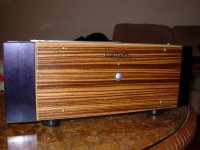
So, earlier this year, I decided to put everything into a cabinet. In addition, had seen some streaming source solutions, and thought their LCD screens displaying album art looked very attractive. I think there are special albums released with amazing album art just to make these products look good......
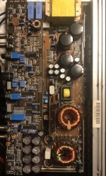
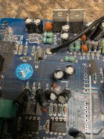
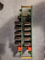
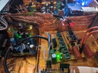
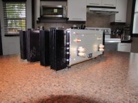
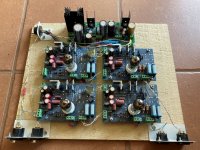
So here is all that needed to fit into the cabinet:
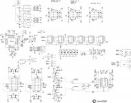
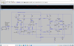
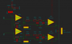
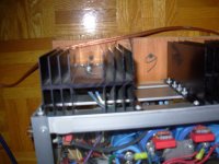
I also wanted to be able to shutdown the RPi gracefully when the front panel power switch was pressed. So I incorporated a delay circuit that maintains power to the RPi for 1 1/2 minutes, when power to the rest of the boards are turned off - the loss of power also triggers a GPIO shutdown in the Pi.
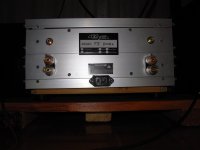
The Pi runs picoreplayer + LMS + squeezelite + jivelite. LCD is Waveshare 5" touchscreen.
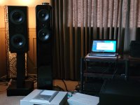
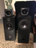
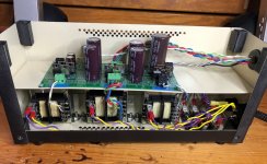
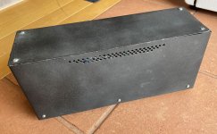
End result below


So, earlier this year, I decided to put everything into a cabinet. In addition, had seen some streaming source solutions, and thought their LCD screens displaying album art looked very attractive. I think there are special albums released with amazing album art just to make these products look good......
So here is all that needed to fit into the cabinet:
- Raspi + Allo digione
- Soekris R2R DAC
- Soekris I/O board (Normunds) with source selector and LED indicators
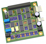
- PGA2311 volume control board with analog input selector and volume control
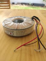
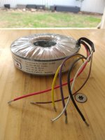
- 1 power supply for the analog board (just transformer)
- 1 power supply for the Soekris (DiyInHK)
- 1 power supply for the Raspi+Soekris I/O board + LCD (Sigma 11)
I also wanted to be able to shutdown the RPi gracefully when the front panel power switch was pressed. So I incorporated a delay circuit that maintains power to the RPi for 1 1/2 minutes, when power to the rest of the boards are turned off - the loss of power also triggers a GPIO shutdown in the Pi.
The Pi runs picoreplayer + LMS + squeezelite + jivelite. LCD is Waveshare 5" touchscreen.
End result below


