Hi - I'm considering using an existing chassis for a new build. With the valve holes already cut I need to consider using a 9-pin noval double triode as driver or driver/phase splitter for a 6AS7 to provide a PP output. I would normally use a 6SN7, however that's an octal base big valve. I've read that an E88CC is a sort of 6SN7 equivalent but would love to hear suggestions, especially from people who've done this.
Final question, is a 6SN7 a good choice for the pre-amp stage? I would look to use a single 6SN7 to provide L and R channel pre-amp, to then feed the noval phase splitter/driver, in turn driving a single 6AS7 for a PP configuration.
I know it all sounds a bit a$$-backwards, hence some sanity checking.
Thanks in advance!
Last edited:
6CG7 is a noval version of the octal 6SN7. 6AS7 triodes require fairly high driver voltage swing to produce usable output, so it is difficult to judge whether it will work in your case. Please post the schematic you have in mind. You may also look at several schematics for some ideas of functional designs. Here is one:
http://bjl.audioconcept.free.fr/Arc..._Tubes/6AS7/P.P/The_VDV_6AS7(The Maurits).pdf
http://bjl.audioconcept.free.fr/Arc..._Tubes/6AS7/P.P/The_VDV_6AS7(The Maurits).pdf
I saw 'novel' in the title and thought this was something 'new'. I think you meant 'noval' as in 9-pin miniature tube. 😉
Just to clarify... Are you thinking the setup would be a separate line-level control preamp connecting to a PP 6AS7 power amp? If yes, then...
A 6SN7-based line stage is not a bad thing. Its output impedance would be pretty high (roughly 8k ohms) but you could put a MOSFET source follower on its output and bring the output impedance down to just a couple hundred ohms or less. Gain of a 6SN7 line stage would be anywhere from about 10x to 16x, depending on the particular design.
A noval (9-pin mini) twin-triode will be needed for each channel of your power amp. That means two noval twin triodes in a stereo amp.
The 6AS7 is also a twin triode. That means one 6AS7 per channel. or 2x 6AS7 for a stereo amp.
Something like a JJ ECC99 or a Russian 6N6P could be used as the phase splitter/driver for a PP 6AS7.
6FQ7 or 6CG7 could also work. Also 6GU7 or 12BH7A.
Any of these will need to be fed a fairly high voltage B+ so they can swing enough volts to drive the 6AS7s.
As Francois G pointed out, 6AS7 will need a lot of voltage swing at its grid to be driven to full power. Probably 60V peak or it could be much more, depending on how much power you're trying to get, the operating point you pick for the 6AS7s, and what OPTs you use. (The circuit Francois G linked to would require 140V peak or 280V peak to peak voltage drive. That's a massively tall order for any driver stage!)
What OPTs are you planning to use? That could be the most important decision right there.
Last edited:
1. If you use a long tailed pair (LTP) phase splitter/driver, remember gain will be less than u/2.
A 6SN7 LTP gain will be < 10.
2. A gain stage of 6SN7 (gain </= 20) driving a 6SN7 concertina phase splitter (gain </= 1.0), will have slightly less than a gain of 20.
3. A 6SN7 paraphase splitter will have a gain </= 20.
The maximum peak output swing of the 3 types of phase splitter/drivers will be less than Bias Voltage x gain:
With 10V Bias:
1. LTP 10V x 10 = < 100V
2. 10V x 20 = < 200V (if you can get the concertina to swing that far, probably not.
3. 10V x 20 = < 200V
You will have to design carefully to get this much linear peak voltage output. And it needs to swing linearly for both the positive and negative peaks (peak to peak voltage).
Personally, I prefer (1.), the LTP using a solid state current sink (yes sink, not source), in the parallel cathode circuit.
And I do not think I will ever use a 6AS7 for the output stage, not my kind of tube.
You may find that you need a gain stage, phase splitter/driver stage, and output stage in order to get the gain you want/need:
depending on your signal source amplitude.
Happy designing, happy building, and happy listening!
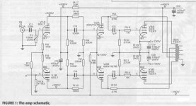
I have constructed a 6AS7G PP with 6SN7 driver and 6SL7 voltage amplifier/phase splitter (schematic attached).
During that process I also simulated a Noval version with LTP phase inverter and hi-mu triode voltage amplifier stage.
In general, optimum operating condition for 6AS7G is Ua = 250 V / Ia = 50...55 mA. Load impedance = 5k. With these values, the AC-signal level required to drive 6AS7 is some 240...250 Vpp. This can be done if supply voltage available for phase inverter is more than 360 Vdc.
6AS7G should be operated with cathode bias, then the overall supply voltage required is some 380 V.
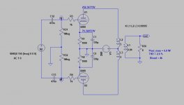
Attached the schematic of LTP-version of 6AS7G PP too. Voltage amplifying stage contains one half of 6N2P-EV (12AX7) and LTP is done with one 6N1P(-EV).
During that process I also simulated a Noval version with LTP phase inverter and hi-mu triode voltage amplifier stage.
In general, optimum operating condition for 6AS7G is Ua = 250 V / Ia = 50...55 mA. Load impedance = 5k. With these values, the AC-signal level required to drive 6AS7 is some 240...250 Vpp. This can be done if supply voltage available for phase inverter is more than 360 Vdc.
6AS7G should be operated with cathode bias, then the overall supply voltage required is some 380 V.
Attached the schematic of LTP-version of 6AS7G PP too. Voltage amplifying stage contains one half of 6N2P-EV (12AX7) and LTP is done with one 6N1P(-EV).
Attachments

Artosalo,
Thanks for the schematics!
I see that the 6N13S schematic uses one adjustable plate load (82k series resistor and a 47k rheostat).
That provides a method to compensate for the sum of any un-balanced gain of the driver and any un-balanced gain of the output stage.
(With equal splitter plate loads, the splitter balance is automatic/intrinsic; but the driver and output stages are not automatically/intrinsically balanced).
It is perhaps a good idea to adjust the gain balance without any negative feedback applied; and only then apply the negative feedback after that.
Right?
What supply voltage are you planning to use?
If doing 250-300 volts for the output stage something like artosalo suggests would work well, as would a Williamson type front end.
Most of my experience with the 6AS7 has been at 100-200 volts for the output stage- it makes them require much less voltage swing to perform well if you aren't chasing every last bit of power.
Well... Back when I was building tube amps and I had a push-pull power amp working, I goofed around with biasing output stages with a giant variable voltage regulated B+ supply and variable fixed bias, with a two-stage "dual-diff" push-pull driver stage running from its own +440V B+ supply. From that primitive experiment, I decided I like the sound of the output stage running with a lower B+ voltage and at higher plate current (more in Class A, less in Class AB). I found that as I biased the output stage colder, the sound got somehow 'leaner' and I need to add more NFB to make it sound like I liked it.
So I could see setting a push-pull 6AS7 at something like 175V plate-cathode with plate current of 75mA or so. The grid voltage would be about -81V. That still means you want a driver stage that can swing 150V peak into the 6AS7 grids. The downside is that you'll be burning up like 50W of plate and heater power to get a meager 6W audio output per channel (not counting the plate and heater power dissipated by the driver stages). Not efficient at all, but at least the OPT primary impedance can be nice and low, making it easier to find a well-performing OPT. What would you use for that, maybe 3k:VC? 4k?
On the other hand, a 6AS7 isn't the most linear triode. It's plate curves start leaning over to the right pretty early.
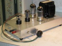
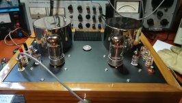
Here is a real live PPP 6080 Amp in hardware, built more than 20 yrs ago.
With a 400V supply about 20W of audio. And it really has a novel driver, a bootstrapped 6SN7GTB.
Unlike most other amp projects here on DIY there is real test data to backup performance.
The often used test 'Sounds OK' is not a great reference.
Each of the 6080 cathodes needs its own Rk. And probably heatsinks. The OPT is a special
built for me by Hammond, 2150 Ohms P-P.
Attachments

Nice one!
Are the taps on the primary of the OPT wound like 'ultralinear' screen taps? Or are they something more unusual?
Was this design featured in an article in Glass Audio?
Are the taps on the primary of the OPT wound like 'ultralinear' screen taps? Or are they something more unusual?
Was this design featured in an article in Glass Audio?
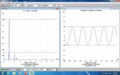
I fully agree. I actually avoid those discussions where this become the most important criteria of the performance.The often used test 'Sounds OK' is not a great reference.
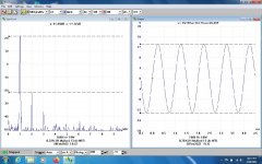
Attached some test data of my 6AS7G PP amplifier.
Attachments
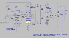
Here is the simulation of the 6AS7G PP output stage with lower (~180V) supply voltage and 4k load impedance.I decided I like the sound of the output stage running with a lower B+ voltage and at higher plate current (more in Class A, less in Class AB).
Compared to 250 V plate voltage, the output power is 50 % less and THD about 35% less. (6W vs. 12W and 2.6% vs. 4%)
With 250 V plate voltage/ 50 mA current, the operation is in class A too.
Attachments
Thanks to all - some great responses and content. I might well revert back to the original purpose for the chassis, ie single ended. I could parallel the two triodes together in the 6AS7G which would half the matching impedance required for OPT, which would hopefully allow me to have a higher power single ended OPT? I could stick to ECC83/12AX7 for the noval pre-amp/driver stage and that should allow enough volathe swing to drive the 6AS7G.
The taps on the OPT are the normal UL taps at 43%. I’d done the initial work on the project with OPT's I had on hand with 20% & 43% taps. Then I went to Hammond with a request for something like their 1650N but ½ the impedance. In the final circuit four triodes in two 6080s drive into 2150 ohms.Are the taps on the primary of the OPT wound like 'ultralinear' screen taps? Or are they something more unusual?
Was this design featured in an article in Glass Audio?
Part One of this project was published in the Volume 11, Number 2 Issue of Glass Audio magazine in May 1999. Part Two appeared a month later in Volume 11, Number 3 Issue of Glass Audio magazine. A circuit simplification which avoids the use of the Ultra Linear Output Transformer in the first article is covered.
The original circuit also appeared in short form in the July 1999 issue of Electronics World.
Attachments

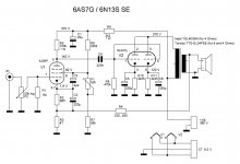
Hi - what is the primary impedance of the OPT? With the two triodes of the 6AS7 in parallel I understand it's best matched to a primary of 1800 Ohms, compared with a primary of 3400 Ohms for a single EL34. Thanks.I have also done 6AS7G SE. Attached the schematic and test results.
The OPT mentioned is for parallel EL34 in SE ...Hi - what is the primary impedance of the OPT? With the two triodes of the 6AS7 in parallel I understand it's best matched to a primary of 1800 Ohms, compared with a primary of 3400 Ohms for a single EL34. Thanks.
OPT specs
... so 1650 Ohms impedance.
Yes, 1k65 with this OPT: https://sklep.toroidy.pl/en_US/p/TTG-EL34PSE-Tube-output-UL-transformer-1,65kOhm-EL34-6L6-PSE/577
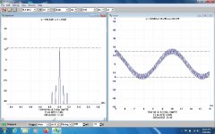
I also used an other OPT with 1k75 load impedance (Indel TGL20/004). Attached the test results with that.
I also used an other OPT with 1k75 load impedance (Indel TGL20/004). Attached the test results with that.
Attachments
- Home
- Amplifiers
- Tubes / Valves
- Novel driver for 6AS7