Roundover vs. 45º Chamfer vs. Double 22.5º Chamfer edge treatments for tweeter diffraction.

Hello,

I have always wondered how much difference there was between a roundover and a 45° chamfer. Jeff Bagby once told me to treat a chamfer as a roundover with modeling programs that didn't specifically list chamfer as an edge option.

An edge treatment I have not seen is a double 22.5° bevel, it would seem to be similar to a roundover, but not require a big expensive roundover bit or be hard to veneer.

While various modeling programs allow different sized roundovers and show specific angles, I have been curious to see the incremental difference in edge treatment size as a full range of off axis measurements.

Here are three test baffles that I will be testing incrementally larger edge treatments of roundover, 45° chamfer and double 22.5° bevel with a full range of off axis measurements.

Test tweeter will be a Seas NoFerro 900.

Here are the blanks I will be testing on.

Attachments

  • 20220312_214953_resized.jpg
    20220312_214953_resized.jpg
    856.5 KB · Views: 406
  • 20220312_232102_resized.jpg
    20220312_232102_resized.jpg
    717.3 KB · Views: 319
  • 20220312_232822_resized.jpg
    20220312_232822_resized.jpg
    791.1 KB · Views: 395
  • 20220313_125119_resized.jpg
    20220313_125119_resized.jpg
    788.5 KB · Views: 425

Toyota Tundra audio parts to beat girlfriend's Harman Kardon in her Volvo.

I need help guys! My girlfriend has a premium Harman Kardon audio system in her car. We both love it. She is teasing me about my Tundra's crappy stock sound system all the time. Yes, it is not amazing for sure. I also LOVE clear real sounding music, opera, classical music and hip hop.

My plan is to build an amazing sound system in my Tundra which equals or sounds better than the all around rich, detailed sound of her Volvo.

So HELP ME!!! I am desperate.

My Tundra is a non JBL system, no amplifier and no subwoofer. It has 6 speakers. (2 front, 2 rear and 2 on the instrument panel. no tweeters. )

I would like to replace the stock radio. (Android audio wouldbe great and reverse camera input, the rest I don't care. I just wan to have crystal clear sound...)

Budget: under $1000 or maybe $1500? I am willing to buy used amplifiers, speakers, etc!

Please help a Toyota owner to impress his girlfriend!!!!

Looking for 1933 article - Franklin Institute

I recently got another classic - Fred Terman's* Radio Engineering. I came across a reference to what could be the first documented use of a cascode or SRPP or similar with tubes: The use of a Vacuum Tube as a Plate Feed Impedance by J. M. Morton. It was published by the Franklin Institute vol 216, December 1933.
Posting this in the small chance that someone has a copy and would be willing to share.

Jan

*Professor Frederick Emmons Terman was Bill Hewlett's promotor at the time and later helped him to set up Hewlett & Packard together with Dave Packhard.

QSC HPR152i waveguides

I have a couple of these waveguides (WG) and the Dayton D250P-8 compression drivers (CD). I first tried a passive crossover at ~1.5kHz to Beyma 15LX60V2. Used the Clio system and MLS measurements. I got the crossover to have a distinct 1.5kHz cancelation with the polarity of one of the drivers switched. So I think the phase at the crossover frequency isnt too bad. But it sounds like a pair of old megaphones. The beymas measure ok, but I dont know how well they actually sound up to 1.5kHz.

I tested a bit more with an old 8" woofer using minidsp for crossover. That sounded a lot better. Not honky, but very laid back. A bit distant even.

So I dont know if the problem is with the WG+CD or the combination of woofer and WG+CD.

One thing I also noticed is that the waveguides I have are quite rough. The first inch or so of the waveguide is not very smooth. It is a bit bumpy. Is this normal? Does anyone have these waveguides and can check? I am a bit worried that I got a bad pair of WGs.

🟢 loudspeakers SB Acoustics 4 way Under development.

Olá a todos do fórum!
Há anos procuro sites especializados em muitos projetos de 4 vias mas nada me agradou ou atendeu minhas expectativas.
Por isso resolver reunir pessoas interessadas no mesmo tema e juntos desenvolveremos um bom projeto.
Não sou especialista em análise acústica, mas sou mestre em marcenaria e sou apaixonado por áudio.
muito de realizar esse projeto gostaria com a linha SB Acoustics, separei os modelos:
Satori TW29RN-B-8
Satori MR16P-4 6"
Satori MW19P-4 7,5"
Satori WO24P-4 9,5"
ponto é que a rota outro deve ser fechado
https://www.madisoundspeakerstore.c...ori-tw29rn-b-8-ring-dome-tweeter-black-8-ohm/
https://www.madisoundspeakerstore.c...16p-4-6-egyptian-papyrus-cone-midrange-4-ohm/
https://www.madisoundspeakerstore.c...19p-4-7.5-egyptian-papyrus-cone-woofer-4-ohm/
https://www.madisoundspeakerstore.c...24p-8-9.5-egyptian-papyrus-cone-woofer-8-ohm/
  • Like
Reactions: wasabii

Nakamichi MCT1 Mods

Dear all,

I'm planning to make some modifications to an old car stereo Nakamichi MCT1 (from late 80´s). Inspired by Lukasz Fikus from Lampizator, my plan is to put 2 Mullard ECC70 subminiature valves on the DAC outputs, creating an analog valve stage.

If that can be done, I want this device to convert the digital signal from other sources, such as a cell phone, multimedia system, etc... My idea is to transform the auxiliary input into a digital input for the Dac, in USB format.

This is the help I need from the more experienced members of the forum: - Is it possible to use a USB interface like the Amanero one, connecting its digital output (maybe i2s) to the Nakamichi's auxiliary inputs, and internally divert this signal to the DAC?

All connections are made via pins located on the bottom of the device support drawer, which fit into the back of the device.

Any help is welcome, and I appreciate everyone who can contribute.

Attachments

  • Nak 1.jpg
    Nak 1.jpg
    339.7 KB · Views: 203
  • Nak b.jpg
    Nak b.jpg
    375.1 KB · Views: 150
  • Nak c.jpg
    Nak c.jpg
    341 KB · Views: 168
  • Nak d.jpg
    Nak d.jpg
    328.5 KB · Views: 148

1st issue digital CD releases vs streamed/downloaded later re-issues

Wonder how you guys feel to what I say below?

Playing "original non-remastered" CD's are usually so much better to my ears in dynamic range, than any new (just louder) CD's that been remastered, and that are usually used by streaming/download companies, which have been dynamically compressed.

(but compression does have it's place and is good for "music on the move in noisy background situations" car, iPod, ear buds etc etc)

Original first issues CD's are the best for dynamic range, which gives the music and your brain a "chance to breath", you can't have "loud" if you have no "quite"
Here is just one example of a classic one only made album but re-issued many times of a British–American supergroup consisting of Bob Dylan, George Harrison, Jeff Lynne, Roy Orbison and Tom Petty. " The Travelling Willburys"

Look what happens the younger the re-issues become
Green is good (uncompressed), yellow (fair), orange and red (compressed rubbish)
https://dr.loudness-war.info/album/list/year?artist=Traveling+Wilburys

Cheers George

Yamaha A-960 No audio output

Good evening everyone ! I have this Yamaha amplifier that does not deliver an output signal and when I turn on the relay does not activate! I have replaced all the electrolytic capacitors and measuring with the tester on the 2 pins TP4 and TP3 I have 9mv! Do you know anything about it?

Attachments

  • 20220315_165244.jpg
    20220315_165244.jpg
    548 KB · Views: 311
  • 20220315_165233.jpg
    20220315_165233.jpg
    489.9 KB · Views: 532

Audio Note Double C-core

Hi all,
years ago I bought these transformer from Tom

https://www.diyaudio.com/community/threads/tubes-and-tube-stuff.126131/post-1559652

I used them, a friend of mine used them, and we both moved to different setups and these OPTs are not needed anymore.

For operation I made an "aluminum shroud", which I can take away, or just leave in place.

I think the current code is T305-3-55-H306H306-S

Who is willing to put them to good use? These are very heavy!

best regards,
Erik

Attachments

  • 2022-03-17 11.35.20.jpg
    2022-03-17 11.35.20.jpg
    344.1 KB · Views: 228
  • 2022-03-17 11.35.30.jpg
    2022-03-17 11.35.30.jpg
    248.6 KB · Views: 216
  • 2022-03-17 11.35.46.jpg
    2022-03-17 11.35.46.jpg
    265.3 KB · Views: 219
  • 2022-03-17 11.36.11.jpg
    2022-03-17 11.36.11.jpg
    335.3 KB · Views: 208
  • 2022-03-17 11.36.23.jpg
    2022-03-17 11.36.23.jpg
    334.4 KB · Views: 230

Nakamichi MCT1 Mods

Dear all,

I'm planning to make some modifications to an old car stereo Nakamichi MCT1 (from late 80´s). Inspired by Lukasz Fikus from Lampizator, my plan is to put 2 Mullard ECC70 subminiature valves on the DAC outputs, creating an analog valve stage.

If that can be done, I want this device to convert the digital signal from other sources, such as a cell phone, multimedia system, etc... My idea is to transform the auxiliary input into a digital input for the Dac, in USB format.

This is the help I need from the more experienced members of the forum: - Is it possible to use a USB interface like the Amanero one, connecting its digital output (maybe i2s) to the Nakamichi's auxiliary inputs, and internally divert this signal to the DAC?

All connections are made via pins located on the bottom of the device support drawer, which fit into the back of the device.

Any help is welcome, and I appreciate everyone who can contribute.

Attachments

  • Nak 1.jpg
    Nak 1.jpg
    339.7 KB · Views: 110
  • Nak b.jpg
    Nak b.jpg
    375.1 KB · Views: 105
  • Nak c.jpg
    Nak c.jpg
    341 KB · Views: 99
  • Nak d.jpg
    Nak d.jpg
    328.5 KB · Views: 96

SUBWOOFER VELODYNE

Olá, tenho tido problemas com subwoofer Velodyne modelo DD . Anteriormente, eram problemas no módulo de potência. Recentemente, peguei dois subs com problemas comuns no stand by. Eles desligam por falta de sinal e não ligam quando o sinal voltava, algumas vezes também o display,, só voltando a funcionar quando desligados (desenergizados) Sendo que o problema volta a se repetir cada vez mais. Será que alguém pode me ajudar com isso? Obrigado!!!

:cop: This is an English language forum.
You must post here in English. Below is the translation of your post,

Hello, I have been having problems with Velodyne subwoofer model DD . Previously it was power module problems. I recently got two subs with common stand by problems. They turn off for lack of signal and do not turn on when the signal came back, sometimes also the display,, only going back to work when turned off (de-energized) Being that the problem repeats itself more and more. Can anyone help me with this? Thanks!!!

Help chosing high SPL drivers for 3way classic loudspeaker

Hello all !

Not so long time ago, a thought started appearing in my mind..

I was looking at this excellent project Faital-3WC-15


And in mist of it all, i bought pair of brand new Visaton BGS 40 for fairly cheep BGS 40 - 8 Ohm | Visaton


I know i know, its not the same as that Faital 15PR400, but hey, im on tight budget... 1/4 of 15PR400 price to be exact..


Anyhow.. now i need to find appropriate drivers to go along with these Visatons.
I plan on using almost identical box design as Troels.

Since Visaton peaks around 92db @200hz, which i think is good place to cut it i was thinking it could be paired with rest of the drivers from Troels design, aka.

Midbass - 18 SOUND 8NMB420 (8 Ohms) - Eighteen Sound - Professional loudspeakers


Tweeter - Satori TW29RN-B-8 - https://www.madisoundspeakerstore.c...ori-tw29rn-b-8-ring-dome-tweeter-black-8-ohm/


What do you guys think ? Would such abomination actually work ? Will some other driver make a better fit with that Visaton ?

Thanks.

Quad 303 Power Amplifier parts for DIY or Repair Amp

Quad 303 power amp full set of resistors and capacitors for full set of PCBs(3 boards)excluding inductors and transistors.
This sale is not included the full set of PCBs(3 boards) PCB boards sold separately at my other auction.
You can purchase at
https://www.ebay.com/itm/255449244937?hash=item3b79f62509:g:SZ0AAOSwNlFhRFTO
and also visit my store for other items.
Thankyou!

Attachments

  • s-l1600-1296.jpg
    s-l1600-1296.jpg
    132.2 KB · Views: 129
  • s-l1600-1297.jpg
    s-l1600-1297.jpg
    96.3 KB · Views: 162
  • s-l1600-1299.jpg
    s-l1600-1299.jpg
    73.1 KB · Views: 130

looking for MagneQuest TFA-2004 Pinstripe or other parafeed output transformers for 300b project

Hello all, looking for magnequest output transformer’s for custom amplifier project. 300b,45, etc.. will consider all types: nickel, cobalt, pinstrip, silver etc.
also whole bottlehead kits are fine as well: Bottlehead Paraglow monoblocks, kaiju ..

Attachments

  • E030A3F8-5EAC-4AA3-8D69-580E17BED85F.jpeg
    E030A3F8-5EAC-4AA3-8D69-580E17BED85F.jpeg
    556.8 KB · Views: 129
  • 3EE0AD9A-5937-448D-BFA0-719032EE5B60.jpeg
    3EE0AD9A-5937-448D-BFA0-719032EE5B60.jpeg
    461 KB · Views: 108

simple low power composite amp using UTC TDA2050

Once understood how a composite amp works i had the idea to build one as simple as possible. The prototype works stable, so i gave the new KiCAD 6.0.1 a try to design a new board. Here is my result. The board is not yet ordered so i will not show any measurements.

Attachments

  • simple-composite-2050-circuit.png
    simple-composite-2050-circuit.png
    1 MB · Views: 464
  • simple-composite-2050-2D.png
    simple-composite-2050-2D.png
    804.9 KB · Views: 456
  • simple-composite-2050-3D.png
    simple-composite-2050-3D.png
    376.7 KB · Views: 426

Price Gouging

I was looking for a matched pair of 5751 pre-amp tubes for an upcoming project. A month ago - before Russia invaded Ukraine, they were readily availab;e for about $40 plus shipping. Now I looked and I was shocked at some vendors. For example, Vivatubes listed matched pairs in the $120-$140 range. Outrageous.

I went to my usual reliable sorce - Doug's Tubes. Doug Preston was much more reasonable. Under current circumstances, price increases are understandable. He had a matched pair of Sovtek 5751s for $53 plus shipping. I received them four days after ordering. Thanks Doug!

Alpine MRP-M650 multiple chip failures, need specs

So I just got this amp in, only 2 output mosfets were blown @ Q402 & Q406 (removed all output FETs) 1 of 4 50v/3.3pF caps at E103 was pushed off its lead and leaked, replaced all 4 caps, board powers up, about 1a current pull at idle.

I see a sawtooth and both square waves on the c494GS.

Neither IR2010S show anything other then voltages, no waves of any kind.

No square waves at output sockets and voltages are all over the place at each empty socket, tried figuring out which were high and low but man they are just all screwy, to a layman anyway lol.

Diode “S120” @ D305 near IR2010S (murs120 I think, 200v but 1a or 2a?) is testing bad on DMM. Can’t find anything else wrong/blown.

All 3 resistors @ R404, R405, R406 all look popped, 6.8 from markings, same other 3 diodes @bR410,R411,R412 ran in parallel are at 2.3 as should be.

There’s another post on this board with similar issues, ordering IR2010S and Murs120 chips but which murs120? I’m seeing 1a and 2a versions, I asked a vendor if he could tell by pic of diode and he couldn’t and I can’t find a service manual. I want to replace both IR2010S and the diode at D305 but don’t know it’s exact spec, anyone know?

Attachments

  • image.jpg
    image.jpg
    687.4 KB · Views: 228
  • image.jpg
    image.jpg
    644 KB · Views: 193

VU meter install on Bluetooth 5.0 & Classic TPA3116 chip

Hello everyone. This is my very first post, as I am reaching out to a community that I hope will understand what it is I am trying to do. And also know that in terms of circuit knowledge, I am not very fluent in the actual names and terms used. Please go easy on me. That being said, I'm not stupid either. I base a lot of my building and designing on common sense and research. I know the basic "in's" & "out" of electronics, but in lay mans terms. Ok, all of that aside, here is my question...

I am building a Bluetooth receiver amplifier based on the 2.1 channel Bluetooth 5.0 & Classic TPA3116 chip, specifically this one ==> (https://www.amazon.ca/gp/product/B0836NL1Q2/ref=ppx_yo_dt_b_asin_title_o06_s00?ie=UTF8&psc=1) and I want to incorporate left and right 12 level LED VU meters, this one ==> (https://www.amazon.ca/gp/product/B09S5PFZCS/ref=ppx_yo_dt_b_asin_title_o04_s00?ie=UTF8&psc=1) into the build.

I understand the basic principals of how VU meters work, signal out-put levels vs volume out-put levels and so on. I understand that in order in achieve or grab a signal out-put it needs to be a low level out put. Or I'll fry the VU meter controller board.

Here in lies the rub... The only out-puts the TPA3116 board has are the speaker out-puts (left, right & sub) one 3 pin in-put and one 3.5mm in-put jack. That's it, no headphone out-put at all.

So, let the trial and error begin. First, with very low volume, nearly nothing... I try to tap into the speaker out-put just see what happens, other than the power supplying the controller board of the VU meter nothing much happens. then I ask myself, where have I heard "high to low level" before? And I remember having to do a sub install in a car and had to use a "high-low line level converter" to grab a signal from one of the rear speakers to which would run VIA RCA to the amp. So I tried it, and it "kind of" worked. But it work in the way I believe a volume or gain level works not a signal level. Alass, I have come to the end of my trial and error point with what ever basic knowledge I have.

SO, here is where I need your help as a community of helpful and understanding people to help my understand where I am going off the rails trying to achieve what I want to do. In the best of lay-mans terms you can muster. I have no idea if the board can support what I want to do or where to tap into to get the VU meters to do what they are intended to do

Thank you in advance for your patience's and understanding and most of all help.

Building the RJM 6dj8 phono preamp

All,
I'm going to start building RJM's 6dj8 phono preamp soon. I've built the VSPS phono stage and the Wyn Palmer phono stage ( like both a lot!), but those had build guides and circuit boards. This will be my first point-to-point amp. I have a few questions and was hoping those with more experience would be able to help:
  1. Does the attached layout of one channel of the amplifier circuit look ok? I've read that layout is very important for tube phono stages to be quiet, but don't exactly know what that implies for the layout of the amplifier section. I tried to set everything up with the minimal number of connections and short signal paths. I don't think I'll need any jumper wires. Also, the two rectangles between the tubes are terminal strips, just so I won't have any floating point connections.
    1. Does the grounding scheme look OK? My plan will be each channel will have a ground bus, and then those ground busses will be wired to a single star ground point on the chassis. The power supply ground will also be going to that star ground point, which will then go to the ground prong on the power inlet.
  2. The power supply will be in the same chassis. I'm planning to try a variant of Eli Duttman's power supply. I will use the same transformer (Allied 6k1vf) and his plan for the B+ to get a regulated DC voltage of 250V for B+. The Allied 6k1vf transformer has a 6.3v winding for the heater filaments of the 6dj8 tubes. So my plan is to first try wiring the 6.3v secondaries directly to the heater filaments. If that's noisy (excess hum?), I will try an artificial center tap or humdinger on the heater filaments. If all of that fails, I'll have to figure out how to create a regulated DC voltage for the filaments
  3. To start, I'm planning on using a pair of 6922 tubes that I have, just to check if the amp is working. Does that sound OK? My understanding from a bit of research is that the 6922 tube is equivalent to the 6dj8, maybe even built to tighter specifications, but I'm not sure. I could get a pair of 6dj8 tubes if that's advisable once I verify the circuit works.
    1. My understanding is that pin 9 connects to an internal shield between the two triodes contained in the glass envelope. Should I attach pin 9 to ground, so the shield is grounded?
Thank you in advance for your help!!!
Dan

Attachments

  • RJM6dj8_onechannel.jpg
    RJM6dj8_onechannel.jpg
    313.3 KB · Views: 490

My DIY LM3886 Amp

Although not my first 3886 build but this time i'm doing it for my own use :sly: 
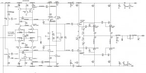
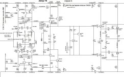
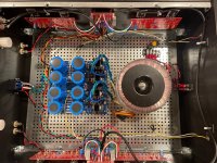
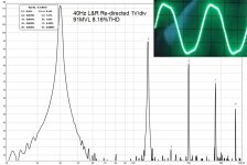
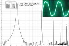
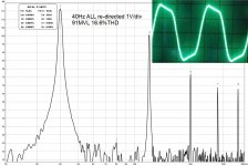
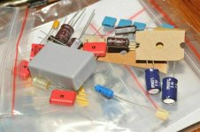
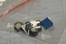
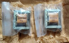
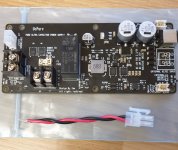
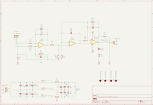
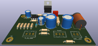
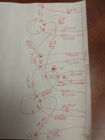
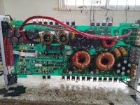
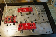
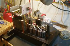
I sourced couple of PCBs which has a really nice & usable layout. Very straight forward build, nothing fancy & i am not following pcb schema. I set the input impedance to 22k & gain around 27dB. Skipped feedback compensation network & didn't use any capacitor between the Inputs but added RF blocker(from signal In to ground, 235khz low pass). As input cap i used 1uf mkt from Vishay & for Ci i'm going to use 100uf bipolar. I planned 100uf Nichicon muse BP for that place but their footprint is little bigger so placed a new order for 100uf 16v Elna RBD bipolar & will settle this later. Anyway as on board supply decoupling cap i used 1uf film with 470uf 63v electrolytic per rail. I don't have solid polymer or X7R ceramic at the moment so used general purpose elco with 1uf film instead.

On the other hand for PSU i made my own board, 3x4700uf per rail without bypass capacitors. 220VA transformer & 35amp bridge.

GC.jpg
20220305_204811-1.jpg
  • Like
Reactions: pbilous and srdjant

F5t v2 for sale Michigan

For sale and for local pick up only is my f5t v2. It was built with care but on a budget so the parts are all first class, new, no knock-offs...the heat sinks were made from recycled Pentium processor heat sinks ;-)

I mounted those heat sinks to 14mm aluminum sheets and then those plates are housed in a wood framework. The power supply pictured has been since altered to use a large torroid instead.

This was not my first build but not my last either so I sell it to afford more builds!

Come see and test it. It's a rocking good amp!

Cannot ship this monster, it's too heavy.

$600.00 USD

Attachments

  • f5tv2 with preamp.jpg
    f5tv2 with preamp.jpg
    314.8 KB · Views: 360
  • f5tv2 right side bits.jpg
    f5tv2 right side bits.jpg
    417 KB · Views: 351
  • orig pwr supply.jpg
    orig pwr supply.jpg
    382.6 KB · Views: 352

New Curve Tracers?

I am in the market again for a Transistor curve tracer mainly for matched fets and output devices. whats new out there worth buying??? I don't want used, old that i need to rebuild/recap etc etc. I dont want a kit i have to build, i want something new and semi affordable i can use right out of the box. Under say $2000-$2500

I see madell has one that looks similar to the old tek units....anything else out there worth looking that???

Slone amp final solution ?

Hi All
I want to know how a Full Complementary Symmetrical power amplifier sounds and add it to my RCP130 collection.

After reading that Mr. Slone symmetrical IPS with mirrors might suffer from undefined VAS standing current, I searched and found several solutions:

https://www.diyaudio.com/forums/solid-state/335074-bryston-4b-sst-clone-7.html#post5920143

https://www.diyaudio.com/forums/solid-state/335074-bryston-4b-sst-clone-10.html#post5930001 chalky

https://www.diyaudio.com/forums/sol...ogy-construction-troubles-25.html#post5951772 Cordell

https://www.diyaudio.com/forums/sol...logy-construction-troubles-4.html#post2177541 E Stuart

https://www.diyaudio.com/forums/sol...pology-construction-troubles.html#post2163428 BV

https://www.diyaudio.com/forums/sol...logy-construction-troubles-2.html#post2169779 BV

https://www.diyaudio.com/forums/sol...logy-construction-troubles-2.html#post2169816 BV

https://www.diyaudio.com/forums/solid-state/99252-mini-class-amp-3.html#post1413451 GK

https://www.diyaudio.com/forums/sol...mosfet-normal-diamond-buffer.html#post1120959 fab

http://www.ne.jp/asahi/evo/amp/J200K1529/report.htm JAP

https://www.angelfire.com/sd/paulkemble/sound3.html JLH


I simulated some of them and found that all solutions did never provide the promised Low THD from the original design.

I know Bob Cordell's solution to work well at the expense of some THD deterioration.

Here I want to share a solution that provides excellent THD figures while not being too sensible to temperature variations and beta mismatches.

In my implementation I connected a feedback resistor from the VAS emitter Q3 to the input stage mirror input leg emitter Q10 and adjusted the emitter resistors
So to have nearly the same Vdrop over R2 and R11 (+-700mV)

I built this amp based on the files below, I found it to be quite sensible to temp variations and the currents over R11 R38 (VAS emitter resistors) are never steady.

It seems the both positive and negative VAS are trying to set idle current and as it is never exactly the same, they tend to "fight each other" creating a permanent fluctuation.

Decreasing the feedback resistors R12 and R39 helps minimize this fluctuations but OLG is severely reduced.
I listened to it for a while and although HF is very extended and clear, LF suffers from some blur.

Then I had one idea.... why not fix the current only on the top VAS bjt Q3 and let the lower one Q5 to follow ?

In simulation, even with a very low feedback resistor R12 (1k) I have a fixed current in both VAS and best of all, OLG is only slightly affected.
Now I have 111dB OLG until 600Hz
108dB @ 1KHz
59dB @ 20KHz
0dB @ 1.18MHz (66° PM and 22dB GM)
Damping factor into 8ohms is 5Mohm until 1KHz and 34Kohm @ 20KHz

It took me a while to get the TMC right but now this amplifier is a top contender.
HF is crystal clear and very extended, LF presentation is FullOn with increased detail compared to my Blameless and voices are realistic.
This amplifier sounds more natural and almost reaches the "Meridian 103 Magic" in terms of instrument placement and depth of image.

For general information I am leaving here the last EVO8.33 that represents the actual build I am now enjoying.


Kind regards

Attachments

Pass F5 Turbo $1000

SOLD 3/28/22

Can't edit post title, now $750.

My time with this sweet sounding class A amp has run it's course, and I'm ready for something that's a better fit for my lifestyle. I'm happy to let it go for $750. Shipping should be about $150, I attached a screenshot FedEx ground estimate.

All MOSFETs have been replaced with matched MOSFETs from DiyAudioStore. I have several posts regarding this exact amp on the forums (Illustrated F5 Guide, and F5T Builders Thread).

More details
  • The chassis, was a group buy from "Ultimate 4U 500mm Chassis" on this forum. Came from Italy, modushop here. I had the front laser etched with (IMO) a really cool subtle text. The front aluminum plate is 10mm thick (took me a while to cut that switch hole in it!)
  • Transformer is a bit oversized, Antec AN-8425 - 800VA 25V Transformer (weird! I checked my order receipt it said AN-8225, but the pic of the actual transformer in my hand is AN-8425... <shrug> )
  • Cardas XLR inputs, not hooked up
  • diyaudio Universal Power Supply, 8x 22,00uF capacitors digikey
  • new metal feet for the chassis (ones that came with it were sorta cheesy plastic numbers)
  • 2x 3.0a slow blow fuses in the IEC
a hum
I can barely hear it when my head was 12 in away from the speakers. I suspected the green AC switch up front may have had something to do with it, and disconnected it, that wasn't it. It's been re-attached, as it's a pretty and functional switch.

I've attached some pics I snapped tonight of details of the amp. If you'd like a link to the Google Photos album of the entire build, PM me.

It will be a sweet amp for someone out there, thanks for looking.

Drew

IMG_7003.JPG

Attachments

  • 158usd shipping guesstimate.png
    158usd shipping guesstimate.png
    36.7 KB · Views: 248
  • IMG_7002.JPG
    IMG_7002.JPG
    403.8 KB · Views: 212
  • IMG_7004.JPG
    IMG_7004.JPG
    410.1 KB · Views: 205
  • IMG_7005.JPG
    IMG_7005.JPG
    350.9 KB · Views: 190
  • IMG_7006.JPG
    IMG_7006.JPG
    354.7 KB · Views: 187
  • IMG_7007.JPG
    IMG_7007.JPG
    428.3 KB · Views: 175
  • IMG_7008.JPG
    IMG_7008.JPG
    452.9 KB · Views: 189
  • IMG_7009.JPG
    IMG_7009.JPG
    297.6 KB · Views: 222
  • IMG_6714.JPG
    IMG_6714.JPG
    720.4 KB · Views: 257
  • IMG_7074.JPG
    IMG_7074.JPG
    226.2 KB · Views: 167
  • IMG_7077.JPG
    IMG_7077.JPG
    207.7 KB · Views: 144
  • IMG_7078.JPG
    IMG_7078.JPG
    265.6 KB · Views: 142
  • IMG_7079.JPG
    IMG_7079.JPG
    219.7 KB · Views: 158

New here, not new to tubes

Hi all! I found your forum while searching the web for some answers and ideas concerning a tube amp I was building. I just finished building a tube amp kit from Douk and have it working well. I've been wanting to build one from scratch using largely my own design and layout. It's actually on my bucket list" to do this. I have most parts purchased, now all I need to do is find the time to get busy on it. I'm trying for about 30w per channel, but I wont get into that here. I've been into electronics since a kid, even building a PP 6V6 tube amp from parts I had around as a teenager - from a repair book schematic! It worked fine!

I spent the 1st 20 years or so of my career working on TV's and such for Sears, (thus my user name) catching the very end of the tube sets in the mid 1980's. I gave it up in the early 2000's when things went to board replacements and alignments on projection sets and switched over to small engine work. Weird I know, but I learned mechanics off my dad (he was a mechanic) and electronics off my uncle (a US Navy radar tech), so it wasn't a big change for me. I always had an interest in the hobby, especially tube electronics but lost interest when the parts vendors closed and parts & info was difficult to get. I boxed stuff up and threw it in the attic.

I found a Philco 70 on eBay and began investigating things and found with the internet, I could not only find parts again but also information and support groups. After completing the resto on the 70, I took a room upstairs - (had to remodel my sons room to accomplish) - and created my "radio room". modeled after a write up in an old Marcus & Levy book from the 1950's, restored my test equipment (some built by my uncle), and began my renewed interest in the hobby.

I have restored and repaired quite a few radios, TV's and guitar amps, and built a couple ChiFi amps with good results, as well as a couple AM radio transmitters. Now it is time to me to venture out and build my own. I am mostly interested in HiFi tube amps, and some guitar stuff. Yeah, I play too. I haven't been super pleased by most of the offerings I've found - seems to me there is kind of a gap between the lower power stuff and really high power stuff. Not much in the middle ground. Most China kits are single ended, which work fine, and more recently, a lower powered PP kit (just finished it) but get frustrated by the lack of documentation and often have to work out problems. I even made a set of instructions for my 1st build and made a list of notes with this latest. Anyway, I think there will be a wealth of information here and will share what I have learned as well. I'm old school and not the best in math either.

Can I plug a 6n1 tube in a slot thats been a 6n2 tube?

:cop: Two threads merged 13:12 UCT Feb 23 2022


I am considering purchasing a Dared MP-5BT on Amazon and the listing noted that the tubes used are 6N1 and 6N2 side by side. Since these tubes are a little hard to obtain currently I was wondering if there are equivalent tubes for both? I was also wondering if the sockets are wired to accept 6N1 equivalents in both or only 6N1 and 6N2 side by side? Thank you!

I saw on some forums where people used the same tubes in both sockets but I wasn't sure if that was for an older model of the MP-5 or something.

I'm wondering about AD745

Somebody I know like the AD745, ultra low noise JFET input opamp from Analog Devices.

Q1: Why only SOIC16 wide as the only package? Any clue? Before they had SOIC08 and DIIL08. I'll guess this has to do with market since it's rather old (1990).

Q2: Is this the best JFET opamp in the world in noise perspective?

Q3: Anybody why used this opamp lately besides Sigurd?

http://coset.se/tmp/Audio/Hagerman/OPampAdaptersNo011.jpg
http://www.audiocircle.com/circles/viewtopic.php?t=21339

Help with a 3 way hybrid active-passive crossover

I'm trying to design a 3 way speaker with a passive crossover for the mid+tweeter, and use active crossover with the twin woofers using minidsp 2x4 HD. Will be used with 4 ohm stable amplifiers.

The parts I'm considering are
Tweeter: SEAS Prestige 27TBCD/GB-DXT
Midrange: SB Acoustics SB12MNRX2-25-04
Woofers: 2 of SB Acoustics SB15SFCR39-8

I'm getting a feel for how the passive crossover might look like, using the manufacturer supplied graphs and vituixcad.

Attached is my first attempt. Please ignore the response below 300 Hz. I don't have any response shaping components in the network because I'm planning to do that (and room correction) using the DSP.
All I'm looking for right now is
  • A reasonable response
  • Good off axis response
  • Reasonable phase response
  • Not a big loss of efficiency

I'd like to get some feedback on how this network will behave. Am I going in the right direction? Any suggestions to improve it?

Attachments

  • 3_way_sb XO-schema-1.png
    3_way_sb XO-schema-1.png
    14.1 KB · Views: 336
  • 3_way_sb Six-pack.png
    3_way_sb Six-pack.png
    152.4 KB · Views: 283

2sk82 or 2sj28 vfet pair for sale

Hi, Looking to sell one of the following:

1 pair 2sk82 kd-33 rank (no special matching, purchased as a pair way back when from acroman) $350 Sold

OR

1 pair 2sj28 kf-33 rank (no special matching, purchased as a pair way back when from acroman) $350

Paypal F&F and includes usps flat rate shipping. Other methods for actual cost. Prefer US sale. I only have 1 pair of each. Since I'm sure it will be asked, I would be willing to sell both pairs plus a pair of the 2016 version of the vfet amp bracket for $850.

Thanks
Chris

Focal sopra 3 diy alternative ?

Hi everyone,
Keen to start diy project to build something as close as possible to Focal Sopra 3 specification and sound quality wise, as can not afford to buy one. 🙁
More then confident to utilise my skills with building cabinet and finish, but have no clue about drivers and crossovers , in a past just did simple diy speakers sett reusing some old drives and crossovers matched to it. Essentially removing all hardware and fitting to newly made cabinet.

for this project like to make something more substantial and something that could be enjoyed for years to come and nice to look at! Have good idea of cabinet size and design, something like 170x45x55 would be very acceptable. Have workshop where can do all woodwork and finish.
Have budget of 1500£ excluding cabinet build so just drivers.
For around that price I can buy focal 926 but after listening to sett of those in shop was wishing for more bass and not impressed with look of cabinets. That’s why Sopra 3 looks like something I would enjoy to listen to and look at!
Was thinking about using Seas drives, so could do with advice reg matching it all and calculating exact internals of box size required, crossovers ect.
Open to idea of having to build active subwoofers at base of unit with integrated amplifier and running rest from my Marantz p7000n.

Subwoofer Amp 2x IRFP240/ 2x IRFP9140

Hi people,

I'm currently building my first solid state amp. I've built a fully active 7-channel 2.1-system with chipamps and it works great. I'm totally happy with it, and there is no need to change anything. Right now I should be on the ocean, saving the whales, or somewhere else curing beautiful daughters from virginity ... . But, you know ... .
I think these speakers will be under construction for a long time.

A few days ago a parcel from China arrived with PCB's for Cap Multipliers, TDA7293 parallel chipamps and a pretty simple mono MOSFET amp, I found while surfing the EasyEDA open source projects. At the moment the Subwoofer, a MIVOC AW 3000 in 50l sealed, is powered by two TDA7293 in parallel configuraton running at +/-32,5V and about 70000µF/rail. It goes deep, it's dynamic, I like it.

I just want to find out if this MOSFET Amp is maybe doing the job even better. I want to run it with a little higher voltage and I'm aiming for a 28-0-28V/ 500VA toroid.
This amp is not audiophile champions-league and I think, as a SW-amp it doesn't need to be. It just shall deliver buckets of current (also for the next chassis; the GRS SW12-4HE seems to offer a lot of "boom" for the buck).

Ok, now I got to order caps & MOSFETS, so I got a break and a few questions:

For VT6 I took a BD139 instead of a BD135. Is that ok?
R13 is marked with a star (?), as far as I know (I'm just a mechanic) is this the place for the BIAS adjustment. I couldn't find any description about this. Should I use a 1k trimmer instead of a 750R resistor, or shouldn't I care?
I added a Zobel with 10R/1W, 100nF at the output, ok?
IRFP9240 are hard to get, the 9140 should do the job, but there are two versions 9140 and 9140N. Which one should i choose?

Ok, thats it for now. Many thanks in advance for your patience with a newbie 😉 .

best regards
J.

Can you really tell the difference between two tweeters?

As with any driver, if equalized to the same end results, what sonic characteristic difference may you tell, in materials, driver behaviour, etc?
Two tweeters reproducing the same frequencies, equalized the same, everything being the same, would they not also even sound the same?
Dome tweeter vs. a compression driver, is there a leap of progression in utilizing a compression driver instead, or it's all about implementation?
Would a larger voice coil (same throat) naturally equal to a more "natural/present" sound, sounding less boxy or muffled, or what are its benefits?

OPPO BDP-105 Sends CLIPPED signal on sub out for movies with strong re-directed bass!

First of all, to the Mod's: I know there there is already a thread about this player but what I've found here is huge and I wish somebody had showed me the following data before I wasted over a thousand dollars on this device so I believe it's worth it's own thread...


An externally hosted image should be here but it was not working when we last tested it.

This is a waveform from the end of the movie Earth to Echo. The waveform with the red border is taken from the analog sub out on a 200 dollar old 1st or 2nd gen Panasonic bluray player. It fades into the green border's waveform which is taken from the sub out of the OPPO BDP-105. Here is a closer view...
An externally hosted image should be here but it was not working when we last tested it.


What started me on this discovery is my friend maxmercy over at Data-Bass Forums made a disc to test the worst case scenario of re-directed bass in 7 channels added with LFE. Using this disc (a more comprehensive version will be available sometime this summer with many more tests on it) can help find where your preamp's analog sub out starts to clip so you can set your gain stages up accordingly and never push clipped signal to your amp and subs.

What I found is that the 105 can handle a near full reference level (-0.1dB) LFE track at any frequency with the MVL (master volume level) all the way up to 100 without clipping. But as soon as you add even the center channel's re-directed bass with it, it starts clipping and from there the more channels you add of re-directed bass the worse the clipping gets. The WORST part is: it doesn't matter how low you adjust the MVL or the sub trim, the clipping does not go away! It is a problem with how the 105 sums the signals and adds it to the LFE channel so there is no fix for this.

I understand that there isn't going to be many movies with all channels outputting only sine waves in the low frequencies but like I said, this was a worst case test to have a good idea where to set your analog out's (MVL for reference and/or sub trim control) so that a worst case will not take out any amplifiers or drivers in your system. With loudness wars now infiltrating more movie soundtracks full of square waves in multiple channels, we might as well start setting our systems up accordingly.

Look at the following attachments to better understand how the 105 deals with re-directed bass:

Attachments

  • 1Hz Scope.jpg
    1Hz Scope.jpg
    71 KB · Views: 273
  • 5Hz Scope.jpg
    5Hz Scope.jpg
    80.5 KB · Views: 249
  • 10Hz and 20Hz.jpg
    10Hz and 20Hz.jpg
    82.1 KB · Views: 263
  • 40Hz LFE.jpg
    40Hz LFE.jpg
    103.4 KB · Views: 149
  • 40Hz Center.jpg
    40Hz Center.jpg
    92.2 KB · Views: 157
  • 40Hz L&R.jpg
    40Hz L&R.jpg
    90.3 KB · Views: 149
  • 40Hz LCR.jpg
    40Hz LCR.jpg
    94.4 KB · Views: 145
  • 40Hz 7channels.jpg
    40Hz 7channels.jpg
    97.5 KB · Views: 148
  • Trim level vs distortion.jpg
    Trim level vs distortion.jpg
    76.2 KB · Views: 142
  • Volume vs distortion.jpg
    Volume vs distortion.jpg
    103.3 KB · Views: 140

Menno Vanderveen EL84 amp: PLITRON inside

Hello,

For sale a complete amp from Menno.
Very nice and professional build.
Schematic available and Menno still available as well 🙂 Safe buy!
AFAIK Plitron OPT are no longer available (at least at Menno specs)
Completely tubed with Russian valves, lovely sound.
Selling as I don't use it...

Asking price 750 eur
Shipping is available, not cheap as it weight a lot, and fragile. So will be double boxed.
But happy to discuss.

Open to partial trade with triode preamp.
.
IMG_7800.JPG

IMG_7659.JPG
IMG_7660.JPG
IMG_7802.JPG
IMG_7801.JPG
IMG_7800.JPG

SOLD THANKS

System gain structure

Yes, of course, read the good thread by Plano. My question is not where in the system we amplify or attenuate. My question is different.
Speakers have different sensitivities, but I think, their amplitude is reasonably linear with respect to power.
Amps have gain, but as it is a ratio, and it varies amp to amp. The higher the power, the higher the gain.

So, I have a mains amp with 23 dB gain.
I have a sub amp with 27 dB gain.
I can use attenuators so at some point, say 1W, the amplitude to either side of the crossover is the same. But what happens at 5W? 50? Am I not driving the sub proportionally much louder than the mains?

Class H power transformer question

Hello,
I was given very nice and massive power transformer which came from my friend Pioneer multi-channel receiver. It has single primary and dual secondary windings. I asked my friend to make a picture how it is wired before removing it. The pictures show secondary windings to be connected in parallel. At first I thought things are easy: two secondary windings (red and white) plus black wire which I thought is ....connected to screen. I have measured resistance among windings which are:
  • Primary (blue/brown): 0.7 Ohm
  • Secondary (red/red and white/white): 0.5 Ohm
Just curiosity forced me to check connectivity between red and white windings and they are connected. I was also surprised to see connectivity of black wire to both windings. At first I did not know this is H-Class receiver. My friend also sent me pictures of output stage which consists of three STK modules: two STK-412 and one STK-413. I checked them on the net and they are H-Class integrated chips. The only information I see about the transformer is printed on secondary windings PCB: 94V - 0V.
My question is not about H-Class, but about possibility of using this transformer for non-H-Class power supplies. Can I use it and how connection of secondary windings should be made?
Thank you very much for the help.
IMG_0142.jpg
IMG_0141.jpg
IMG_0137.jpg

Be gentle - first time poster with a problem with a Proceed amp

I was referred here from a post on AVS. As I look around this forum, I can tell I am out of my league. But I have a problem that hopefully you guys can help me out with.

I have a Proceed HPA 3 that has died. About 5 years ago I had a similar card failure and sent it off to be repaired. The repair was completed and all was well until this weekend. Had the same failure as before. The unit powers up for a second then goes into self protect mode. I isolated the bad board down to the center channel.

An externally hosted image should be here but it was not working when we last tested it.


Before I do anything else I would like to try and fix this myself.
I have also checked all of the resistors and believe they are good. Except for two components that look like resistors to me, especially because of the way they are marked. One is black, the other white.

I have taken some pictures of the bad board and of the board that was repaired earlier. If I visually compare the two boards, it is apparent that the repair shop simply added a new component over the old one. The shop used the same replacement component for both of the failed components. It is labeled:

TRC LF
8k 66 1%
The pictures below show the old versus new for the two components.

The white component is a:
CP-5 Mexico 9913
1.8K OHM 5% Dale 5W

And the black one is a:
IRC
2k74 TO
9849

Repaired board:

An externally hosted image should be here but it was not working when we last tested it.


Bad Board

An externally hosted image should be here but it was not working when we last tested it.


Repaired white component

An externally hosted image should be here but it was not working when we last tested it.


Repaired black comonent

An externally hosted image should be here but it was not working when we last tested it.


What I would like to do is get some help in determining what the correct replacement parts are and where to order them.

I will then use my meager soldering skills and try to make the same repair as the previous repair and see if I can get this amp working again.

Am I crazy to try this, or should I turn this amp into a boat anchor?

I do not claim to be electronically inclined, but want to try and fix this problem. I also have a Proceed Amp 5 that has crapped out as well, but that is for another time. So let loose with any questions or criticisms, as I would like to see if I can power up this heavy amp.

This last picture is of the bad component showing what looks to be some discoloration due to excessive heat (As in it let the smoke out
An externally hosted image should be here but it was not working when we last tested it.
)


An externally hosted image should be here but it was not working when we last tested it.

__________________

adding digital input to a YBA CD player for use as a DAC ?

I have a YBA Lecteur CD player that sounds amazing. I've never heard a 'modern' CD player or outboard DAC so I don't know if the DAC in my CD player sounds so good because it's the only one I have, or because it really does sound good. Anyhow, it does not have a digital input. I'm wondering if it's a big project to add a digital input to this thing so that I can use it as both a CD player and an outboard DAC ????

Attachments

  • download.jpg
    download.jpg
    7.9 KB · Views: 430

Technics SLP777 Soad 70 mystery or misery

Hi everyone,
I could use some help/advise on repairing my Technics SLP777 CD player.
It started skipping and taking time to read the toc.
I did some research online an found out it was probably the laser. Good news tho, I read that technics had used the Soad 70 laser assembly in a few models of that era.
I purchased a good secondhand lower model and started the laser assembly swap.
I had both machines side by side. I removed the cover off them both. Great news, like I had read the lasers assemblys were the same.
I took my laser assembly out it the 777 and replaced it with the good one from the lower model.
I swich on the power and inserted a cd into the draw. The cd spun up and went really fast. Then stopped and started to spin in the other direction. Strange.
I put the lower model laser back in to its original machine and it played fine. So I tried it back into the 777 again, Checked all the cables etc.
The same thing happened. Spun up really fast then stopped and spun in the other direction.
So now what. Well I tried my faulty laser assembly out of the 777 in the lower model machine. It played just like it did in the 777. Slow to read the toc and skipping especially when playing tracks towards the end of the disc.
Any ideas would be greatly appreciated.
kind regards

ORCAD SCH/PCB LIBS

Does anyone know where I can get some Orcad PCB and Schematic symbol libs for more recent versions that use Allegro?

I have searched High and Low and find nothing. I can't even find the ones I used have for the old Layout.

I have found an octal base at snapeda.com - that's all. It was under 6l6GC I think, but the symbol was completely wrong, I mean it was fubared.

Really just looking for some noval dual triode e.g. 12ax7 and some octal beam tetrode e.g 6l6, 6v6, el34. I can easily modify
and build on just a couple of those.

Hope someone can help.

Thanks
pm

Super Chokes for VFET Amps 0.1H 5A in EU perfect for THF51 or 2SK180

Hello,
I've for sale a pair of 5A 0.1H 0.4ohm 3,2Kg each
They was made by Megahertz Audio .
150eur for the pair plus shipping.
I'accept Paypal friends or bank transfer.
I'm looking for a pair of Hammond 193T and an Hifiberry Digi+Pro as partial trade.
I can ship from Italy or Germany.
Best regards
Guglielmo

Attachments

  • choke1.jpg
    choke1.jpg
    167.5 KB · Views: 163
  • choke2.jpg
    choke2.jpg
    227.9 KB · Views: 167

New PSU Bare Board - Opinion on this ground connection (please)

I purchased two of these boards off that auction website. They will serve as the left and right rectifier sections of the power amp I'm building. Dual-Mono design w/ two transformers. From China but not Chinese junk. Nice quality double sided boards. Everything is pretty straightforward except the large connection to ground labeled GND (lower left corner of attached photo). It shows the connection being made through a resistor of unknown value. The other end of the resistor connects to the central ground trace running through the center of the board. These boards came without a schematic.

I cannot find any reference to connecting a power supply to ground (assuming chassis ground in this case) via a resistor. Can anyone shed light or provide an opinion about the use of a resistor between ground and this board? Thanks!
IMG_6093.JPG

Pioneer M-L11 Modification

I've had this amp kicking around for some time. I don't want it to go into a landfill and maybe I'll take the opportunity to learn something. How complicated would it be to make this into a stand-alone power amp? It was designed to work with an XC-L11 cd/tuner.

All I need is stereo phono outputs and an on/of switch,

Attachments

LEAF Dual 9038Q2M VS Gustard X16 pictures inside )

Hi amigos,

I share with a quick review of an unknown new DAC. (Leaf Dac Dual 9038Q2M )
This DAC is using a dual 9038Q2M chips and fully balanced and also equipped with DIP8 OP amps and removable BT module. It is using the same chips as the Soncoz SGD1 )
At first sight, the DAC is really really well made with quality components and seems to be very flexible = removable OP amps, removable BT board etc
It is compact (168*110*55mm ) and provided with a external PSU brick (5V/2.8A)

I own the Gustard X16 to compare with. )
I will share a more in-depth test when I have listened to it carefully

For the time being : I gave a quick test with the OPA1612 / 1622 and 1656 ; I really enjoy the 1656 and 1612 both have a very linear response and abolutely dead silence between tracks even with my ears glued to the speakers.
It sounds aboslutely nice out of the box but I updated the PSU with a quality German brick PSU.
Combined with my Hypex NC252MP / David Munyon HD Playlist it is really close to my Gustard X16 and just noticed a lower gain. Anyway : I willl test with my favorite HD Audio Playlist soon.

The inputs interface is really amazing @ such a price !
I think that at the price of 145 euros, we have a little treasure there : To be continued...

SPEC :

Audio input: Bluetooth / USB / LVDS / Optical / Coaxial
Audio output: Stereo RCA / XLR / Balanced headphone jack
BT CSR8675 supports ACC/SBC/APTX/APTX-LL/APTX-HD/LDAC
USB XMOS XU208
IIS that supports DSD64-DSD512 de 32 bits/384Khz,
USB that supports DSD64-DSD256 de 32 bits/384Khz
Opitcal that supports 192KHz y DOP DSD64
Coax PCM 44,1 K-192K/24bit.
RCA inputs 2V RMS
XLR inputs 2V RMS
Headphone amp output power: 1.5W/32Ω, 200mW/300Ω
Matched headphone impedance: 16-300Ω


  • Like
Reactions: Alexium

Would you go back to work if you were me?

Many of you know that I quit working about a year ago because of health issues. I've been working hard to get better and making progress but still have a long way to go. I exercise, I eat like the doctors tell me to eat, I have at least two physicals a month and go to the hospital at least once a month for an MRI, CAT scan, or whatever they tell me to do. I am making slow progress but it's two steps forward one step back progress.

So, I spend 20-25 hours a week with activities directly related to improving my health. I have plenty to do with the rest of my time and make it a point to stay as busy and productive as possible. My buddy says it's a shame I'm wasting my talent and that I should find the right job to satisfy my creative drive. So I looked for "Audio Engineers" jobs in my neck of the woods and this company came up on my radar. https://www.resonado.com/ I sent a query explaining why I wanted to work there. I was explicit about needing an outlet for my creative energy and that I would not work a McJob (I actually used that word). I also said I had serious health problems, visual and aural impairment, and would need a lot of time off to go to the doctor etc, and that I couldn't drive.

They got back to me within 90 minutes and want me to visit their corporate office in Chicago for an interview. I'm going to go but I don't know if I really have the energy to keep this up long term. Quite frankly I could drop dead at any time. On the other hand I guess I don't have much to lose any more. I'm not even sure I can commit to this. I do feel much better than a year ago (every waking moment was agony gasping for breath) and my fitness has improved a whole lot.

So what would you guys do? Any advice is much appreciated. Thanks.
Projects by fanatics, for fanatics
Get answers and advice for everyone wanting to learn the art of audio.
Join the Community
507,720
Members
7,885,710
Messages

Filter

Forum Statistics

Threads
406,118
Messages
7,885,710
Members
507,720
Latest member
lms