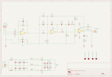
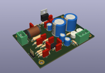
Once understood how a composite amp works i had the idea to build one as simple as possible. The prototype works stable, so i gave the new KiCAD 6.0.1 a try to design a new board. Here is my result. The board is not yet ordered so i will not show any measurements.
Attachments

I found the time to check the THD plot of the circuit shown. Badly it is not much better than the TDA2050 alone - so the circuit needs some change again. I will add an extra feedback-path for the TDA and will see if there will be an improvement.
Since you're tying both the inverting inputs together, the resulting composite amplifier would have similar noise characteristics as the power-amp chip itself. You could return the power-amp inverting input to the error-amp through a resistor if you like (picture).
Attachments

yes, that is another idea of how to share the gain between the two chips. I will give it a try and will see what will perform best
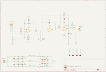
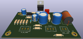
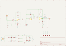
Not as simple as first thought, but here is the circuit i will build a board for. The shown values are the ones that give best performance in simulation and are therefore the ones to start with. The circuit leaves the possibility to check some variation in the circuits topology. This time no SMD-parts.