We'll pick up the story in the middle.
I sent Nelson Pass a schematic back in December to ask if it qualified as an "Aleph-X" circuit. He made encouraging noises, but warned me that I’d have a problem with DC offset. Normally, I would have begun prototyping then, but a virus showed up on my PC and started corroding my stories and, sorry folks, but I had to save what I could of my stories. They make me money. So far, I’ve yet to figure out a way to make audio pay; at least not without going back into retail.
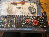
About a month ago I finally got to build a prototype. What you see is the result of my fiddlings, plus a nudge from Nelson. In particular, the very first thing I did after Nelson warned of DC offset was to draw a schematic showing two 1k resistors to ground, one at each output. I tried it, it didn’t work, and no value I regarded as reasonable at the time seemed to make any difference, so I abandoned the idea. Nelson suggested putting in grounding resistors on the order of 30 ohms, which nearly gave me a heart attack. <i>That</i> low? But it worked. I’d like to thank him for that hint, because I never would have gone back and reexamined the idea without a nudge. I had the front end worked out, which by itself will get rid of a fair proportion of the DC offset, but not all. Put in the resistors, and the thing suddenly becomes manageable.
I hereby release Version 1.0 of the Aleph-X.
A word about nomenclature:
--Nelson’s commercial version of the amplifier is called the XA200. I am specifically avoiding calling this an XA-anything, as I don’t want there to be any confusion about this circuit vs. the real thing. It accomplishes pretty much the same objectives, but I don’t know how close it is to what Nelson’s building. In short, don’t confuse the two. Don’t ask Nelson why he did the circuit this way or that. He didn’t. I did. It ain’t his fault. This is just me staying up late at night after I get home from work, trying things.
--I was sometimes referring to the circuit as the Mini-AX during my R&D. I’ve decided to fall back on my earlier name to avoid any confusion with the Mini-A that I did a couple of months ago. Besides, some wag would probably decide that if it’s a Mini-AX, then clearly it must be a hatchet, and I’ve had about all the ‘humor’ I can stand.
--When I say "X," I mean Super Symmetry. A bad habit, I suppose, and I got caught on this very issue in a recent thread, and although most of you will know what I mean when I say X, there is the possibility that someone sufficiently familiar with the Pass Labs product would point out that not all X product is "X." <i>Sigh.</i>
Acknowledgments:
This circuit is directly based on two active patents belonging to Nelson Pass of Pass Labs, 5,376,899 and 5,710,522. In a sense, any circuit built using information gleaned from either or both of these patents belongs to Nelson. Period. If he says desist, ours is not to question why. We desist. Immediately. In particular, this circuit is not to be built for commercial purposes. Nelson has to make a living, and this is his intellectual property we’re playing with.
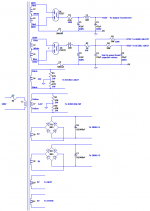
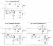
On to the circuit.
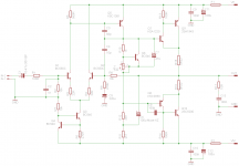
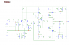
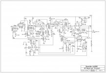
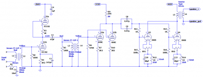
If you’re familiar with the Alephs, the schematic will fit like a pair of old, comfortable shoes. Everything is just about where you’d expect it to be. Well, almost everything. The input resistor network is the same as the Volksamp Aleph models. There are two other things about the front end that will catch your attention. One is the little resistor triptych that I’ve substituted for the usual 221 ohm Source resistor above Q6. Why? Well, that’s the absolute DC offset adjustment. It works by setting the DC voltage present at both of the output stage Gates. Since it’s common mode, i.e. the same current is fed through both sides of the front end differential, it amounts to zilch as far as the signal is concerned. The values I chose will give you a little over 10% play in the front end current, but I needed very little of that with the test circuit.
The other oddity about the front end is the way the signal criss-crosses over to the opposite side. That’s what makes this an "X" circuit. That’s necessary so that the feedback coming in via R16 and R30 will be of the proper phase.
I’ve added two things to the Aleph output stages that aren’t canon: The pots, V1 and V3, and the output resistors to ground. V1 and V3 serve any number of purposes, depending on your point of view. You can run your bias up and down to suit the amount of heatsinking you have on hand or for sound quality purposes. You can view it as a distortion-buster, in that an imbalance in drive between the sides will give you some zillionth of a percent distortion, and you can tune the sides to be in harmony with one another. And lastly, you can use them to zero out small amounts of relative DC offset between the sides. If you want to use them to set the bias, then replace them with a fixed resistor, that’s fine. For that matter, you can replace V1 with a fixed resistor once you determine the proper value. Any remaining DC will be equal across both outputs (like the SOZ, for instance), and the speaker won’t notice it at all. But make sure to at least start with a pot in there, as having 10 volts of DC offset will hamper the voltage swing at the outputs. Get it as close to 0V as you can before you put in a fixed resistor; don’t just assume the standard 221 ohm resistor will do the trick.
There are resistors on each output, going to ground. Nelson suggested 30 ohms. I’ve played with a wide selection of values and can assure you that if you get much higher than 40 or 50 ohms, the thing starts getting pretty twitchy. You can adjust the front end pot all you want, but it won’t stay put. If you use a lower value, it snaps into place quite nicely, but then you’re wasting valuable output power straight to ground, so it turns out that something around 30 ohms really is a pretty good compromise.
The resistors can be removed entirely if you want, but you’ll have to use a servo to tame the DC. I’ve worked one up—discrete, no less—and if enough people are interested, I’ll post that, too. For the time being, the schematic shows the purist way, sans servo.
One last thing, be prepared to fiddle with the values of R12 and R34 in order to balance the current source against the output. Turns out the value is sensitive to the thermal environment, and yours will be different from mine.
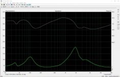
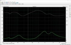
So what’ll it do?
Well, clearly, it’s derived from the Mini-A, which was (given enough current capability) a 10W amp. This is a bridged Mini-A, so it’ll do four times the output, minus a bit for the resistors grounding the outputs, call it about 37W or so. I’ve used .22 ohm resistors for the output MOSFET’s Sources, so it’ll do a pretty good job of servicing a 4 ohm load. If you want to actually double into 4 ohms, you’ll need to go a whisker lower. If you’re confident that your speakers are a level 6 or 8 ohm load, feel free to back off the bias current by putting in, say, .33 or .39 ohm resistors under the Sources. Since the first thing people did after I posted the write-up on the Mini-A was ask whether it would drive 4 ohms, I figured I would start there and let people back up if they wanted to.
If you want more power, you’re going to need to start doubling up on the output devices. That’s pretty easy to do, so I’ll leave that to the individual. (What, you thought I’d give you a full-blown XA200? You’re going to have to work for it.)
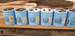
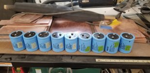
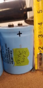
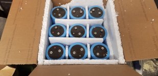
This is a more ambitious circuit than the Mini-A in many ways. It will, for one thing, require a more substantial power supply. The circuit, as drawn, will pull a bit over 4.5 amps. Think in terms of a 200VA transformer, minimum. Lots of capacitance is in order. In fact, you might go so far as to consider a regulated power supply. Nelson just published a nice paper on regulated supplies over at
www.passdiy.com.
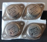
A word about parts is in order. While, strictly speaking, you don’t have to match the output devices for this amp, it’s not a bad idea. The closer the two sides are to behaving identically, the better performance you’ll get out of it, and the less trouble you’ll have with DC offset. That said, I managed to get rid of all DC with a set of unmatched IRF644s.
Which brings me to another, related, point. There’s been a lot of talk about matching parts in other threads. I know I had trouble getting IRF644s to settle down in the test rig—waiting as long as ten minutes before I got figures I thought I could live with. Funny thing...I got in some IRF044s for this project, stuck them in for testing, and the little fellers sat right down and behaved themselves in less than a minute. Clearly, there’s some sort of thermal thing going on here, but I’m still mulling it over.
I’d like to end by noting that I’ve been remiss in answering e-mail for a while, mainly because I only have so many hours in a day, and I needed every available waking moment to work on the circuit. I know at one point not too long ago, Joe Berry sent me a schematic of an Aleph-Xish kind of circuit. It wasn’t like this one, but by the second or third try he had the differential cross-over trick in hand, but nothing in place to handle the DC offset. I believe he was modeling the circuit, rather than building it. What he ever did about the DC, I don’t know, as he was one of the people I quit responding to ‘cause I just couldn’t afford the time. Sorry, Joe. I’m back among the living now, except that I’m so tired I can hardly see straight. Staying up late so much has taken a toll.
Maybe now I can get some sleep.
Except...I had this really neat idea the other day...
Grey
P.S.: I had a more elaborate write-up, but ran into the 10,000 character limit on posts. Bummer. Had to edit the thing pretty savagely to get it to fit. Apologies to anyone expecting puns and jokes like in the Mini-A write-up. There just wasn't room.


