Hello, please need Connection Diagram Eyebrid 4Y80

Hello, have someone a connection diagramm of the amplifier EYEBRID 4Y80. I have a problem with it. Channel 1 und 2 have a strong rush. I don´t know why. The amplifier is at a power supply 13,8V / 10A and with a mp3 player I played some music. Your hear a very strong rush, when the music plays. If you need some picture from the amplifier, I will send it to you by email. Please send me your email address.

Best regards Jörg

AK4399 Based DAC with OPA627 Opamps

For Sale: AK4399 Based DAC with OPA627AU Opamps. Also has teh USB Daughterboard soldered in...

Sounds great, but I need to sell off some gear...

How's $135 Shipped CONUS?

Attachments

  • PXL_20220409_135641233.jpg
    PXL_20220409_135641233.jpg
    184.5 KB · Views: 125
  • PXL_20220409_135700217.jpg
    PXL_20220409_135700217.jpg
    204.2 KB · Views: 139
  • PXL_20220409_135833792.jpg
    PXL_20220409_135833792.jpg
    408.7 KB · Views: 135
  • PXL_20220409_135857208.jpg
    PXL_20220409_135857208.jpg
    386.5 KB · Views: 144

Options for 5U chassis?

Hello,

I am looking around to see what 5U case options are around.

Aside from the Modu ones sold in the DIYaudioshop, what other options are there is the $400 USD price range?

Some are kind boring, already have holes drilled in them for specific switches that I don't want, oversize at 480mm instead of 430mm wide, or just too much money.

Here are a couple decent ones that I found on Ebay and Aliexpress,


lots of silver.jpgperfect case without switch.jpgstylish case.jpg

Either too much silver (1), drilled for a power switch I don't want (2), or offset volume knob (3)

This is the one I am leaning towards,

leaning towards.jpg

What other 430 wide ~200mm tall, ~400mm deep amplifier chassis have you seen out there that are not a million dollars and have a little character?

Thank you,

David.

Quad 306 High DC offset in left channel

Due to being long-sighted (age related). I bridged R13 to C2 on the left channel and lost output in that channel. Since removing the offending solder bridge, I now have +19v DC in that channel. I read somewhere that if you have positive DC offset that means you have a problem on the negative rail. Would that be the case here?
Does anyone know where to look for damaged components? I have a Peak Atlas DCA55 and a multimeter. I also have a desoldering station for quick component removal.

Here's where I messed up:

Quad 306 Bridged R13 to C2.jpg


And here's a link to the circuit diagram.

https://www.audioservicemanuals.com/q/quad/quad-306/19924-quad-306-service-data

Karlson response peaks and dips

I'm posting this in Fullrange since most Karlson enthusiasts seem to hang out here.

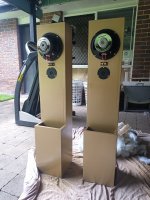
The below link is a recent build of mine, a high aspect ratio Karlson for 6" drivers, which I dubbed Tall K6, TK6 for short. I initially went with a midbass, but finding it unsuitable for the enclosure, I since moved to FF125K and now dual FF125K.

https://www.diyaudio.com/community/threads/karlson-tk6-k-tube.380154/

There are some measurements in the thread, but I will post the ones I think are more relevant here. A Karlson's frequency response is often pretty horrendous, being marred by peaks and nulls. I built a K12 and Super-K8 (really a K10) in the past and took measurement, but lost most of those. The SK8 had the better response, with a dip or two and no major peaking. My present TK6 is interesting as it has all the warts present, of non-negligible magnitude to boot. I though I could pin these down to standing waves easily, but am not certain after measuring acoustically VS physically.

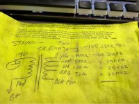
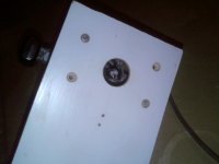
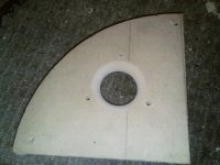
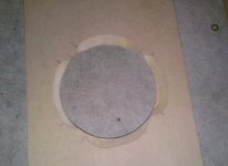
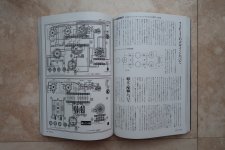
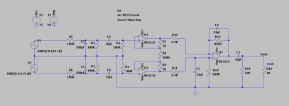
Here is the plan for dimensional reference. The venting was originally done mid-cab through the short horizontal shelf board, but is now four 1" holes at the top of the reflector panel. The short shelf board now reaches all the way to the back panel, but has four 1.5" holes and likely does not contribute much in the way of tuning, or could I be wrong?

tk6_v1.jpg

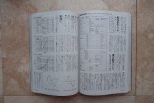
Impedance with 4 vent holes open:

4h_Z.png

Here is the response at 50cm, cabinet elevated 25" from the floor. As all other measurements in this post, I only post the region of interest from 20Hz to 2kHz.

50cm.png

More telling to see what goes on in the lower octaves are near-slot measurements, where I place the microphone on the K-slot's plane a bit above the driver's axis, where the slot is 2" wide or so. I believe that the driver and vent responses are fully summed and room effects are mostly avoided, correct me if this assumption is wrong.

Here is the near-slot response with blocked vent holes, so sealed back.

sealed_ns.png

Here is the response with all 4 holes open, Fb is ~67Hz.

wings_ns.png

Here is the response with all 4 holes open and the wings removed, same mic position as before.

nowings_ns.png

Here is the response with wings removed and microphone at the edge of one vent hole.

nowings_nearvent.png

The sealed response displays the three main issues; a large peak at 300Hz and large dips at 500Hz and 1200Hz.

The ~300Hz peak:
  • It's present on both sealed and vented configurations.
  • It's gone with the wings removed.
  • It also shows up on the near-vent trace, at high magnitude, even higher than the main vent output.
On the vented configuration, this peak is notched by what I believe is the front and back wave 180deg phase difference. This dip also shows on the no-wings trace, but the acoustic pressure is lower because of the larger opening VS wings constriction close to microphone. The peak is however gone from the no-wings, so simple cavity resonance of the front chamber? Why is it of such magnitude, I don't recall having this on SK8, which wasn't worlds apart dimensionally.

The 263Hz peak on the near-vent:

It's present as a small peak on the impedance. Peaking passed the main vent output is usually a standing wave if I understand correctly. Half-wave of 263Hz would need a ~65cm or ~26" dimension. My internal back chamber height is 20". Is it a stretch to say the slightly curvy path + bottom and top thick felt padding add to the height, making it effectively ~25" ? What else could this be?

The ~500Hz dip:
  • It's present on both sealed and vented configurations. It's 515Hz for the sealed config.
  • It's gone with the wings removed.
  • Its depth and exact frequency changes slightly depending on how many vent holes I block, but not by a lot.
It's mostly likely a front chamber effect as taking off the wings completely kills this dip. For the sealed box 515Hz, this is half-wave for 33cm or 13" dimension. Could this correspond to driver to top of cab bounce in the front chamber, even though the one-way distance is ~9" ?

The 1200Hz dip:

This one shows up on most "normal" measurement and is fairly immutable in frequency and magnitude. I have other plots not posted here where it's the same. Even taking off the wings it's not entirely gone. This would be half-wave for ~14cm or ~5.5".

Could the typical shallow vents (board thickness) often used in Karlsons not low-pass filter enough rear-chamber interference? The XKi design's long vent seems to produce better behaved response.

I thought it would be easier to pin these on obvious culprits. The Karlson is a divisive and largely unpopular enclosure, but I like what it can do at times. If anyone cares to venture a few guesses as to my TK6-specific issues, I'd appreciate.

How to reduce Noise in Bluetooth Decoder

I am working on a DIY Bluetooth stereo system, the Bluetooth board which I use produces too much noise.

I am using a 24v 4A SMPS power supply for amplifier board and LM7805 voltage regulator ic for 5v Bluetooth decoder board.
I observed that the noise reduces when I touch the metallic parts in the board.

I am also using the same power supply for the speaker protection board and gain board (regulated 12v).

If I use a separate power supply using 12-0-12v transformer for the speaker protection board, gain board and Bluetooth board, the noise issue will get solved? Also I can use the transformer center tap to ground the body parts!!
Is there any other methods to solve this issue?

Seeking help for Whammy Amp

I recently bought 2 full set of the whammy amp kit. I have no idea why both ended up in the same situation. The first kit sounds very very noisey, like 80% noise and 20% music. I apply quite a lot of "upgraded" audiophile components in the first kit and thought that maybe I have bought the fake components with default. I started to build the second kit which the components are completely from the diystore full kit set. Mysteriously it ends up in the same situation as the first one. I am really confused, and this is why I post this thread.

1.My first idea is my dac are the reason of noise because I test both whammy with that same dac. But it is proved not the sources of noise later on. It works perfectly fine under my speaker and other headphone amp.

2. I have tested every resistor before soldering it on PCB. Only resistor is being checked because I have no idea how to check rest of the components.

3. I solder on both side and I have built few diy design successfully. I dont think it is because of cold solder joints.

4. The +-17V is perfectly measured when I power on the full stuffed pcb.

5. I have double checked every parts is soldered at the correct pad, unless I am conceptly wrong at the very beginning. ( which is the most reasonable explanation why both whammy ended up in same situation. )

I am really confused and sad that everyone seems easily nailed it, except me :*(

Attachments

  • WhatsApp Image 2022-04-03 at 18.38.14.jpeg
    WhatsApp Image 2022-04-03 at 18.38.14.jpeg
    417.2 KB · Views: 161
  • WhatsApp Image 2022-04-03 at 18.38.15 (1).jpeg
    WhatsApp Image 2022-04-03 at 18.38.15 (1).jpeg
    527.3 KB · Views: 174
  • WhatsApp Image 2022-04-03 at 18.38.15.jpeg
    WhatsApp Image 2022-04-03 at 18.38.15.jpeg
    545.7 KB · Views: 179
  • WhatsApp Image 2022-04-03 at 18.38.16.jpeg
    WhatsApp Image 2022-04-03 at 18.38.16.jpeg
    492.5 KB · Views: 172
  • WhatsApp Image 2022-04-03 at 18.38.17.jpeg
    WhatsApp Image 2022-04-03 at 18.38.17.jpeg
    391.5 KB · Views: 161
  • WhatsApp Image 2022-04-03 at 18.38.19.jpeg
    WhatsApp Image 2022-04-03 at 18.38.19.jpeg
    471.1 KB · Views: 165
  • WhatsApp Image 2022-04-03 at 18.38.21.jpeg
    WhatsApp Image 2022-04-03 at 18.38.21.jpeg
    533.1 KB · Views: 157
  • WhatsApp Image 2022-04-03 at 18.38.22.jpeg
    WhatsApp Image 2022-04-03 at 18.38.22.jpeg
    407 KB · Views: 146
  • WhatsApp Image 2022-04-03 at 22.58.23.jpeg
    WhatsApp Image 2022-04-03 at 22.58.23.jpeg
    513.4 KB · Views: 150
  • WhatsApp Image 2022-04-03 at 22.58.24 (1).jpeg
    WhatsApp Image 2022-04-03 at 22.58.24 (1).jpeg
    502.2 KB · Views: 143
  • WhatsApp Image 2022-04-03 at 22.58.24.jpeg
    WhatsApp Image 2022-04-03 at 22.58.24.jpeg
    471.6 KB · Views: 139
  • WhatsApp Image 2022-04-03 at 22.58.25.jpeg
    WhatsApp Image 2022-04-03 at 22.58.25.jpeg
    481.8 KB · Views: 137
  • WhatsApp Image 2022-04-03 at 22.58.26 (1).jpeg
    WhatsApp Image 2022-04-03 at 22.58.26 (1).jpeg
    472 KB · Views: 123
  • WhatsApp Image 2022-04-03 at 22.58.26.jpeg
    WhatsApp Image 2022-04-03 at 22.58.26.jpeg
    494.9 KB · Views: 123
  • WhatsApp Image 2022-04-03 at 22.58.27 (1).jpeg
    WhatsApp Image 2022-04-03 at 22.58.27 (1).jpeg
    564 KB · Views: 134
  • WhatsApp Image 2022-04-03 at 22.58.27.jpeg
    WhatsApp Image 2022-04-03 at 22.58.27.jpeg
    531.3 KB · Views: 154

Apply additional feedback on a class D amp

Hi, I've bought two TDA8932 modules, and their gain is very high, so I would like to ask what is the current state of the art for the feedback to be applied to class D modules.
I read some TI files that suggest to apply a second order filter including the output chokes into the nfb loop, and other files suggesting not to include output chokes.

This is in particular for TDA8932 modules, but also to other modules (I have some IRS2092S modules as well).
I can dramatically reduce gain because I would like to add a simple preamp with triodish sound before them.

Thanks for suggestions.

Roberto

3-way slimline tower speaker build, with photos

Right then, just thought I'd share some pics of my latest undertaking, a 3 way tower speaker.
Driver compliment is Vifa D27TG-35-06 tweeters, Zaph Audio ZA14W08 midrange/upper bass and HiVi D10G woofers.
Cabinets will have a baffle width of 19 cm, overall depth of 44 cm, and a height of about 110 cm.
Standard symmetrical tweeter over woofer layout on the baffle, with the 10" woofer being side mounted. Midrange driver will be in an open back style enclosure, with the partition being on an upwards angle leading to a 40 mm terminus on the rear of the cabinet.
I am also doing away with the tweeters faceplate, and instead integrating the faceplate into the baffle.

These are some pics of tonights progress, I made my own circle jig for the router from some 1/2" mdf sheet, and it works very well. I had ordered a Jasper jig, but it hadn't arived in time and since I paid an extra $20 in shipping to receive my order from Madisound in half the time, I wanted to start as soon as I could 🙂.

I also marked the location of the screws on the cutouts for the mids, and used an angle bit in the router to cut away material from the inside edge of the cutout.

I am hoping to get use of an air powered staple gun tomorrow to help with the assembly, otherwise will just use panel pins to hold it all together while the glue dries. Be sure to check back as I add more photos, and any comments or suggestions are always welcome 🙂

Attachments

  • Screen shot 2012-08-19 at 2.02.28 AM.JPG
    Screen shot 2012-08-19 at 2.02.28 AM.JPG
    127.1 KB · Views: 926
  • Screen shot 2012-08-19 at 2.01.46 AM.JPG
    Screen shot 2012-08-19 at 2.01.46 AM.JPG
    111.3 KB · Views: 883
  • Screen shot 2012-08-19 at 2.01.32 AM.JPG
    Screen shot 2012-08-19 at 2.01.32 AM.JPG
    157 KB · Views: 859
  • Screen shot 2012-08-19 at 2.00.09 AM.JPG
    Screen shot 2012-08-19 at 2.00.09 AM.JPG
    144.7 KB · Views: 855
  • Screen shot 2012-08-19 at 2.01.12 AM.JPG
    Screen shot 2012-08-19 at 2.01.12 AM.JPG
    102.9 KB · Views: 838
  • Screen shot 2012-08-19 at 2.00.57 AM.JPG
    Screen shot 2012-08-19 at 2.00.57 AM.JPG
    112.3 KB · Views: 203
  • Screen shot 2012-08-19 at 2.00.31 AM.JPG
    Screen shot 2012-08-19 at 2.00.31 AM.JPG
    86.2 KB · Views: 219

TPA3116 - need some help

Hi;

I just got this amp from eBay.
TPA3116 Digital Amplifier Board Dual Channel 30Wx2 With Treble Bass Tone | eBay
I ordered this version because it's cheap and it has tone controls - I need them for the project for my father.
First thing is when I touch potentiometers the amp makes some noise. I suppose I need to wire the housing of all potentiometers to ground? Where should those wires go from the housing? To signal ground to the input or somewhere else?
Second thing is this amp has no output chokes (filter). I can't hear there is anything wrong when listening to music because of that but I wonder if it's OK to run the amp without output filters.

I would appreciate some help.

Regards;
  • Like
Reactions: Deric_Maverick96

NAD 3240 PE issues

Hi guys.

I have this NAD 3240 PE integrated amp on my bench that has a bad right channel.

Original symptom - blew F-502 at the power supply and R466 failed open on the 71 volt rail.
Replaced those components and blew F-502 again. Very high offset in the right channel - like 30 volts at the speaker terminals.

Found also Q424 bad - it's a 2SD669 - obsolete, so substituted in a MJE344.

On turn on, blew F-502 and overheated and blew R466 at the same time. Did not damage Q423.

Looking for ideas on where to start with this. Hoping that one of the output transistors isn't gone as they're obsolete also.

Schematic attached.
Thanks!

Attachments

  • 3240_schem.jpg
    3240_schem.jpg
    630.7 KB · Views: 616

For Sale Douglas Self Preamp from Linear Audio 5

This preamp is built off of the DIY project described here:
Amazing preamp with a unique feature set: https://linearaudio.net/douglas-self-preamp-linear-audio-vol-5

Features:
2 XLR and 3 RCA inputs, relay switched
Balanced and SE outputs
Active variable gain. 3x gain for XLR (10dB), 1.5x for SE (4dB)
Max output ~10V (XLR)
HF and LF tone controls (defeatable)
Balance controls
Excellent measurements

Build notes:
Modushop Aluminum 1U Chassis (~17" x 9.5")
Front Panel Express, CNC-milled panels
Kilo USA milled aluminum knobs
Caps - Nichicon Muse (ES), Nichicon Fine Gold (FG), Wima MKP, RelCap Film & Foil Polystyrene
Binned the volume pot for best channel matching -- better than 0.2dB across the entire rotation

It ultimately cost me around $950 to build, since I had to remake both front and rear panels due to errors.
My asking price is $700 + $20 flat rate US shipping.

Reason for sale -- recently bought a Benchmark LA4 to go with my AHB2/DAC3.

Attachments

  • 2022-02-24 01.57.53.jpg
    2022-02-24 01.57.53.jpg
    408.5 KB · Views: 490
  • 2022-03-26 18.00.50.jpg
    2022-03-26 18.00.50.jpg
    527.9 KB · Views: 677
  • 2022-03-26 18.01.33.jpg
    2022-03-26 18.01.33.jpg
    165.6 KB · Views: 447

Can capacitor be bad even the measured value is good?

My preamp has bumblebee capacitors.
The issue is one side channel has huge hum.

I tried to measure with my lcr meter, and value of all capacitors are fine.
Actually, they are still almost double. (I heard it's normal for old caps since they have +80% ~ +100% tolerance is normal)

Still, I can see many cracks on the capacitors.
I know I better replace them all but my question is

can capacitor be bad even they have good capacitance value?
If so, I do I know which one is bad?

Playing with multiple 3" full ranges as mids and ribbon tweeter

I got very good sound out of this kind of playyard which consists of
1. Tapped horn Sub cut at 40hz 54db 2. 15" long throw bass cutted at 370hz and 30db . 3. Triple Dayton PC83s connected series in vertical arrangement cut at 370 and 6200hz and 48db. 4.Dayton AMTPRO-4 ribbon tweeter cutted at 6700 and 48db. ( 6.5 inches Seases inpic are not in use). Result is very much preferring Steely Dan and such funky dry LA-studio sound style. Quality is so much better there is no way going back to use 6.5 inhces unless they could be combined somehow with basses to get more stage acoustics.
Those ribbons are extremely directional and are usable only as nearfield for one person. (But being is extremely good in that capacity) So next step is to deploy some other tweeters to cover more room.
Not related to previous: I wonder if there was any idea to arrage those full ranges as triangle and put classic tweeter in middle? Is there any added value in adding more PC83s?
Array of PC83 plus ribbon tweeter.PNG
  • Like
Reactions: pelanj

WTB …or rent? Speaker T/S tester

Tried to explain it in the title as clearly as I could.

I’ll be getting some vintage speakers that have had some work done on them in the next week or so.

The only way I’ll be able to evaluate them and possibly come up with a plan for an enclosure is to test them for T/S parameters.

I’m located in CT. I figured if there was someone fairly local that would test them or lend their tester for a fee I’d ask.

Otherwise I’d be interested in buying a used DATS or Woofer Tester or similar set up.

Desert Island Albums

There is the excellent British radio show "Desert Island Discs", but its choices are limited to ten songs or pieces of music, which I find too limiting, not to mention impossible to choose.

I prefer the concept of 'Desert Island Albums', which could include sets which used to be 2 or 3 LPs, like Blonde on Blonde, but not box sets such as the complete Beethoven Symphonies. And only have one selection per artist or composer.

With these constraints in mind, I would choose:

  • Electric Ladyland, Jimi Hendrix Experience
  • Highway 61 Revisited, Bob Dylan
  • Kind of Blue, Miles Davis
  • Bach Sonatas and Partitas for Solo Violin (Arthur Grumiaux or Julia Fischer)
  • The Concert for George (Harrison)
  • The Beatles (aka 'White Album') or Revolver
  • Closer, Sarah McLachlan
  • The Art of Renee Fleming
  • Rock of Ages, The Band (or maybe the 1971 Albert Hall concert, just released)
  • Goon Show Classics: Tales of Montmartre/Ill Met By Moonlight/Tales of Mens Shirts/The Whistling Spy Enigma (or really, any four would do, there are over 30 double CD sets)
Predictable for someone my age, but this would give me enough variety and quality of material to work out how to get off the island, plus some humour if I couldn't. I could easily make this list 20 items long but that would be cheating.

Other lists please

Geoff

Stetsom EQ13500EX

Goodnight,

Today I got a stetsom 13500 for repair comes from another workshop where the outputs and the control circuits changed, and they told me that I was now in protection I proceeded to connect it and the amplifier only turns on the red LED and blinks 3 times so I read in Your manual indicates low battery I supplied several input voltages but the status did not change anyone has seen these amplifiers to tell me where to start?

Testing Russian/Soviet tubes

Hi all
Recently I bought a bunch of different Russian and Soviet 6922 tubes. Some are Electro-Harmonix, some are Sovteks (under the RAM label), some are 6N23p Reflector. Since these tubes are scarce now because of the war, I wonder if what I got were some not so perfect ones. I have two tube testers, both calibrated: Eico 667 (so-so, I know), and B&K 747 (more serious). All of these tubes measure bad or borderline in Eico; in BK their behavior is strange: after a few minutes they measure bad or borderline, with needle going lower. If I hold the merit buttons for a while, the needle begins to go higher, sometimes into green (good) area. After I used RAMs in my ARC PH3 phono stage for a few hrs, and tested right away, they tested nearly good, but after a while went down. What is the deal with these tubes? Anybody has similar experience? The store I bought from told me that my testers are no good for testing “modern” tubes. I never have similar problems with my Amperex Holland, or a couple of cherished Mullards.
Thx

STEREO SOUND - Special issue: UESUGI history - My Handicraft. 434 pages of circuits, values, diagrams, schematics and theory behind each design.

STEREO SOUND - Special issue: UESUGI history - My Handicraft. 434 pages of circuits, values, diagrams, schematics and theory behind each design. Brand New book, sealed.

It is written in Japanese but understandable for the DIY. Limited numbers printed. $250.

Photos taken from my copy.

Free shipping within 48 lower states.

Attachments

  • IMG_4811_2.JPG
    IMG_4811_2.JPG
    223.8 KB · Views: 137
  • IMG_4812_2.JPG
    IMG_4812_2.JPG
    310.5 KB · Views: 132
  • IMG_4813_2.JPG
    IMG_4813_2.JPG
    291.3 KB · Views: 126
  • IMG_4814_2.JPG
    IMG_4814_2.JPG
    418 KB · Views: 159
  • IMG_4815_2.JPG
    IMG_4815_2.JPG
    416.6 KB · Views: 137
  • IMG_4816_2.JPG
    IMG_4816_2.JPG
    414.7 KB · Views: 136
  • IMG_4817_2.JPG
    IMG_4817_2.JPG
    181 KB · Views: 135
  • IMG_4818_2.JPG
    IMG_4818_2.JPG
    328.6 KB · Views: 127
  • IMG_4819_2.JPG
    IMG_4819_2.JPG
    381.9 KB · Views: 127
  • IMG_4820_2.JPG
    IMG_4820_2.JPG
    401.5 KB · Views: 126
  • IMG_4821_2.JPG
    IMG_4821_2.JPG
    440.2 KB · Views: 122
  • IMG_4822_2.JPG
    IMG_4822_2.JPG
    458.9 KB · Views: 134
  • IMG_4823_2.JPG
    IMG_4823_2.JPG
    405.7 KB · Views: 120
  • IMG_4824_2.JPG
    IMG_4824_2.JPG
    168.6 KB · Views: 119
  • IMG_4825_2.JPG
    IMG_4825_2.JPG
    305.7 KB · Views: 133

Considerations for nearfield 2-way design?

I'm going to be building a pair of 2-way speakers (with some drivers that I already have), and it is looking like l'll want to use them for nearfield listening too. I think this may be okay; the bass drivers are the scanspeak 15w/8530k01, which have a fairly modest diaphragm diameter of 4.3", and the D2608/913000 tweeters are going to be in Pellegrene waveguides. I feel this combo integrates fairly well already, and I'll also be using active crossovers and bi-amping so there is good scope for upstream tweaking of the driver responses.

I've not ventured into nearfield stuff before. As I understand it, the reduced contribution from the room will mean the bass should be made to roll off less, and small differences in time-alignment and also tweeter-to-bass distance become proportionally more critical. So, I'm starting to think that this project will become more involved with DSP (probably computer-based) than I'd originally intended and that also the baffle might be made with a bit more attention to detail.

But designing for nearfield is new to me; am I thinking along the right lines and/or is there anything else that I should consider or look out for with the design?

Thanks,
Kev

Capacitor types need explanation...

Good day guys im working on an amp (red board) but I need an expertise in making a suitable replacement for that cap value 224k100 (the actual one is 224J100), I took those larger ones from a tv board ac in section, it’s known to parallel caps for higher capacitance and series for less. Can those be used in series to represent the value I need or they’re not suitable for use on the output of a mono amp in parallel to the + & - out?
In conjunction also with a 1k 2watts resistor across the output.
image.jpg

image.jpg

For Sale: Volt VM752 3in Dome Midrange - NIB

Legendary Volt VM752 3in fabric dome midrange driver. New in box (NIB) and never used. A customer bought these for a speaker that I designed for him, but in the end, he changed his mind and wanted to go a totally different direction. These are perhaps the finest midrange drivers ever made. Huge magnet for some of the highest dynamics and lowest distortion possible. Weighs in at nearly 17.5lbs each! Built in CNC aluminum waveguide that also acts as a mounting bezel. Rear mounting only. These cost $914/pair from the factory (not including $114 shipping from UK). For sale at only $680/pair. Buyer pays for shipping (UPS in CONUS is approximately $25 per driver - to be shipped in two boxes to allow easy handling). This is a super deal and won’t last.
A0C0129C-5E33-4976-8700-616A5441B89B.jpeg

E8494E27-AB5A-4B53-8D42-DFC23BA0333E.jpeg

D6D4EC89-B2E3-4243-A0E2-6A5D3D65EECC.jpeg

D784D8BE-BE7F-4AE6-BB60-CC39051659EF.jpeg

F4BC5D94-BC39-4FD2-971E-F2B855876A99.jpeg

A problem that plagues most coaxials

Looking at current offerings by reputable manufacturers, 18sound, FaitalPro, etc.

Most if not all good sized coaxials, 12" 15", even 10" seem to have ugly behaviour in the FR at the upper range of the woofer, where it needs to cross to the CD.

Has anyone any idea, done any research, what is it that contributes to this ragged response in the upper range? It seems to be consistent. A sharp dip, and then some ugly peaks.

Is it the horn mouth opening and expansion in the center?
The deep cone profile?
What the heck?
Why can't they make it right, there seems to be an inherent issue...

Sonic Frontiers Line 2 - no line level output

Hello all, I'm new to this group. I have a Sonic Frontiers Line 2 which I got a few years back, only 1 1/2 years old. The updated tubes burned out, so I put in the original Sonic ones which also burned out after a year. I was using the pre-amp as the main preamp for my stereo and by-pass mode for the surround, feeding my Mirage M-2's with mono/xlr from the Line 2 to OCM 200's. Well the tubes seem to burn out too quickly as the EPL loop is only able to run straight through when the Line 2 is on and after watching lots of movies ... well the tubes burn and I took it out of the configuration.

Back in again a year later and the right two rear tubes would not light up. Swapped L/R and same sockets would not light up. Put it away again.

Now I want to get it working. All the tubes now light up however:
1. no line level output from any unbalanced input (I don't have a balanced source)
2. no headphone output
3. After selecting unbalanced inputs, the display has crazy numbers for three of the unbalanced sources they each display 50 50; 75 75 and some other number and 0 0 for the forth one, so If I were to get output it would be real loud after
selecting the input.

Any ideas on how to trouble-shoot these ? Also is there a way to invert the EPL loop action, so that it is on straight-through with the Line 2 turned OFF (which is the way it should be).

Thanks for any help/advice.
Cheers
Nicholas
(Burlington, Ontario, Canada)

Hello from Brisbane

I have a system I'm proud of that I've put together myself over the last couple of decades and have rarely talked to anyone who knows about DIY home audio.

I have a custom Linux PC that runs PaXoverRack crossover emulation software into an internal ASUS Essence STX II

Then a vertical stacked:

Yayi pure class A valve amplifier
Yamaha 5.1 home theatre amp
Behringer Nu-3000
Nobsound preamp
Behringer Nx4-6000

Feeding: (pairs in the same order)

Vifa 1/2" soft dome tweeters
Morel CAM 558 2-1/8" dome mid
Isobarocally configured Re/Sponse 8" in a 30hz transmission line

Sub:
2x 15" Dyson Audio in a 5m TL
3x Buttkicker concerts

Attachments

  • IMG_20211223_233001_01.jpg
    IMG_20211223_233001_01.jpg
    206 KB · Views: 115
  • IMG_20211223_143409_01.jpg
    IMG_20211223_143409_01.jpg
    205.9 KB · Views: 125
  • IMG_20211231_134551_01.jpg
    IMG_20211231_134551_01.jpg
    262.5 KB · Views: 110
  • IMG_20211231_111947_01.jpg
    IMG_20211231_111947_01.jpg
    505.8 KB · Views: 103

Beyma AMT drivers TPL 200 black mint.

I am about to receive (swapping a pair of speakers) a brand new pair of Beyma AMT drivers, the TPL 200 in black.
One box never even opened, the other driver just opened for measurement... Screw fixing holes never used!
Beyma : Beyma TPL200/B :: PS411.62

They cost £411 each (plus shipping) new so I will sell them for £299 each (plus shipping).
UK buyer preferred as they are heavy and international shipping will be expensive.
I am due to collect them on Friday 30th.
Thanks for reading
Alex.

Soundcraftsmen pm860 fan stuck on high speed

Hello, tryin to reach out to anybody that knows the Soundcraftemen amplifiers. .purchased a pm860 shoe box amplifier that was working great, but not leaving well enough alone I decided to open it up to check the bias. The amplifier was dead on but in the process of checking I accidently touched one of the LM 342 pm15 voltage regulators and it sparked ....now the fan is stuck on high and the 2 red clipping indicators are flashing. ....as for the sound it just sounds intermittent like a stuck CD player.. any body know what controls the fan speed?

Attachments

  • 280D5EB8-65FC-4E86-A6E7-9DD0DB831264.jpeg
    280D5EB8-65FC-4E86-A6E7-9DD0DB831264.jpeg
    737 KB · Views: 300
  • 297575C1-B618-4B49-AA72-9CD202943C80.jpeg
    297575C1-B618-4B49-AA72-9CD202943C80.jpeg
    419.6 KB · Views: 209

WTB Magnequest output transformers

working on several amplifier projects using magnequest transformers loose or in amplifiers, Looking for all TFA-2004 output, nickel,pinstripe, cobalt etc.. but will also consider all other magnequest transformers..
Thank you

Attachments

  • 71C8B3BF-01EA-4898-A365-05EF00465786.jpeg
    71C8B3BF-01EA-4898-A365-05EF00465786.jpeg
    556.8 KB · Views: 129
  • F84BD473-4142-4DBE-BE4A-ED3530369C1F.jpeg
    F84BD473-4142-4DBE-BE4A-ED3530369C1F.jpeg
    461 KB · Views: 136

Leak Delta30

so im making a start on this, and its in realy good condition as it happens

I have no DV voltage at the terminals, which is a good start, just a couple of mv's on each
I do however have 1.8v AC on each channel, im not familiar with this amp yet so i dont know if thats normal or not

Just testing out a few of the old caps and the first one (500uf-64v) is as attached

not sure if this ripple is what it should/would have been) but it isnt bad considering its age

Attachments

  • IMG_20220406_081323.jpg
    IMG_20220406_081323.jpg
    564.8 KB · Views: 99

APEX regulated PSU with Overload and Short-Circuit Protection

I would like to ad an over load short circuit protection to the apexaudio Regulated PSU for my Bench power supply.
I started and asked apex for advises in this thread but I thought that it will be better to start an new thread in the power supply forum.

Thanks steveu who help all ready.


Schematic_1-Apex test_2022-04-06.png


I was also thinking that may be better to have a circuit base of the new transistor biased by a voltage divider network.
Do you thing that is correct like that. Please advise !!!

Winton amplifiers

Hello everyone .
New to group .
Just wondering if anyone would be interested to buy pair Winton amplifiers.

Attachments

  • 2152976C-E68B-4898-A773-F23F6E3EAEDC.jpeg
    2152976C-E68B-4898-A773-F23F6E3EAEDC.jpeg
    367 KB · Views: 179
  • 1AB2CCB2-DFE6-4C40-AD21-C968E0B52A13.jpeg
    1AB2CCB2-DFE6-4C40-AD21-C968E0B52A13.jpeg
    416.6 KB · Views: 184
  • 4A3983AF-CCD5-46F6-B1A3-140189526DE9.jpeg
    4A3983AF-CCD5-46F6-B1A3-140189526DE9.jpeg
    410.3 KB · Views: 159
  • ABEA7BD4-B5C6-4520-BB1D-521951AEAA07.jpeg
    ABEA7BD4-B5C6-4520-BB1D-521951AEAA07.jpeg
    241.8 KB · Views: 137
  • 12491081-6A7E-49B7-8964-BAE2CF04B092.jpeg
    12491081-6A7E-49B7-8964-BAE2CF04B092.jpeg
    277 KB · Views: 196
  • E66CE295-D61A-43F1-B51D-E701741D66D9.jpeg
    E66CE295-D61A-43F1-B51D-E701741D66D9.jpeg
    294.4 KB · Views: 146

B&W 801 Matrix Fried Crossovers??

Hello,

New to this site. I just put together a new system. I have (2) Carver M1.0t with the mkII opt002 upgrade monoblock amps and a Carver C-1 preamp hooked up to a pair of B&W 801 Matrix speakers. They were playing great until I cranked them up a bit. I saw smoke coming from the portholes of both speakers. I turned the volume completely down and let the smoke clear out. Now the mid-range and tweeter are not functioning at all. I assume I smoked the crossovers.

Any suggestions on direction to getting these repaired or parts for the crossovers? Any upgrades I should be looking into?

Thanks for any help you can provide. Happy Thanksgiving!

Trip

Martin Logan CLS II spacer adhesive become loose

Dear Forum!

I am asking if it is possible to re-glue a portion of a Martin Logan CLS II panel that has started to split at the top of the panel (see attachment)
My plan is to find the suitable glue to reattach the split stators. I have some nice clamps to do the job, and glues (eg. chinese 'B 7000' telephone glue)

My question if anyone has any idea which type of glue would stick to the polyurethane(?) spacer and the diaphragm foil?

IMG_1632.JPG

Musical Fidelity A1 Integrated repair/upgrages

I am hoping to get some advice on whether and how to repair my dead MF A1, or whether I should perhaps build another, more reliable, amp instead. If this in not an appropriate forum for such questions, I apologize in advance and ask if someone can refer me to a different forum.

Note that I have limited experience with electronics, so at this point I would only be considering replacing parts on the current amp or building from a kit, rather than building something from scratch.

I have the original A1, the one with the two-part lid and the axial 10000uF caps. The caps do not have any apparent bulges in them.

Here is the problem with the amp. One day, it just failed to start up. So I replaced the slow-blow fuse in the back, thinking this would fix the problem. When I turned the amp back on (with the lid off), I noticed that after a few seconds some of the resistors (R1, R2, R30, & R31) started to glow and then smoke. Now they just smoke instantly when I power up the amp. Needless to say I cannot use the amp in this state.

What I am wondering specifically is whether the amp can be fixed by replacing all or some of the power supply parts (plus the R30 and R31 resistors), or whether I have to test each piece of the amp to determine if there are more extensive failures down the line. What is the best way to determine how to fix this? Or should I even bother? Thanks.

Attachments

  • DSCF2533.JPG
    DSCF2533.JPG
    121.1 KB · Views: 2,533
  • DSCF2535.JPG
    DSCF2535.JPG
    172 KB · Views: 2,927

gstreamer guru needed.

Currently I have a NAS>DLNA/UPNP server.>control point>renderer.
software=(OMV>MoOde>upplay>gmediarender gstreamer 1.0)
hardware=(HP Thin client>RPi3>Ubuntu desktop>another HP Thin client running Ubuntu server with RME HDSPe AIO soundcard)

Playback is working well excepting one small problem...the RME HDSPe AIO has to be set in alsamixer for the hardware rate to match the rate of the file sent and I am lost trying to find a way to have the card (preferably) or file changed to match automatically as different files are played.

Using aplay I can acheive this by putting this in my asoundrc but it doesn't work for gmediarender output.

Code:
pcm.device{
        format S32_LE
        rate 96000
        type hw
        card 0
        device 0
}

pcm.!default{
    type plug
    slave.pcm "device"
}

If I leave the card rate set at 96kHz via ALSA and play a 44.1kHz file I get a gstreamer error..

Code:
ERROR [2022-04-05 12:57:30.360094 | gstreamer] source: Error: Internal data stream error. (Debug: ../libs/gst/base/gstbasesrc.c(3127): gst_base_src_loop (): /GstPlayBin:play/GstURIDecodeBin:uridecodebin0/GstSoupHTTPSrc:source:
streaming stopped, reason not-negotiated (-4)

Seems there needs to be some thing in the gstreamer pipeline or a flag to set the card rate..???

ALPS - Black Beauty atenuator malfunctioning ?

HI, MY TUBE AMP , 300B SE , HAVE A PROBLEM.
THEY HAVE ONE ALPS BLACK BEAUTY EACH CHANNEL.
LEFT CHANNEL OR NOT HAVE MUSIC BEFORE DE 3RTH STEP OR IN THE 4TH IS ALL THE VOLUME , MORE SOME NOISE.
THIS HAPPENED TO ANYONE BEFORE?
CAN THE ALPS BE BROKEN?
CAN THERE BE ANY PROBLEM OF GROUND ?
THE FIRST VALVE SOCKET IS GROUNDED.
UPLOAD A PHOTO.

Attachments

  • WhatsApp Image 2022-04-06 at 4.05.05 PM.jpeg
    WhatsApp Image 2022-04-06 at 4.05.05 PM.jpeg
    186.9 KB · Views: 146
  • WhatsApp Image 2022-04-06 at 4.05.16 PM (1).jpeg
    WhatsApp Image 2022-04-06 at 4.05.16 PM (1).jpeg
    196.7 KB · Views: 146
  • WhatsApp Image 2022-04-06 at 4.05.16 PM (2).jpeg
    WhatsApp Image 2022-04-06 at 4.05.16 PM (2).jpeg
    156.5 KB · Views: 136
  • WhatsApp Image 2022-04-06 at 4.05.16 PM (3).jpeg
    WhatsApp Image 2022-04-06 at 4.05.16 PM (3).jpeg
    117.5 KB · Views: 146
  • WhatsApp Image 2022-04-06 at 4.05.17 PM (1).jpeg
    WhatsApp Image 2022-04-06 at 4.05.17 PM (1).jpeg
    139.4 KB · Views: 152
  • WhatsApp Image 2022-04-06 at 4.05.17 PM.jpeg
    WhatsApp Image 2022-04-06 at 4.05.17 PM.jpeg
    108.7 KB · Views: 149

LTspice simulation for the instrumentation balanced input using NE5532

Hello everyone!

I am having trouble running simulation schematics that I created using LTspice. I used external code for the NE5532 opamp from this website: https://jeastham.blogspot.com/2011/11/adding-ne5532-op-amp-model-to-ltspice.html

For some reason the simulation does not appear to be working. There are no errors thrown, but the output signal comes out as a very small voltage.

I am new to this
Any help would be greatly appreciated!

Pavlo

Attachments

1" throat CDs comparison

here is.... FWIW
The BMS 4526HE-8 measurement was not included. It shown for size comparison sorry!
The amplifier output level was unchanged across.
it's about 12" from the horn mouth.
On axis "eyeballing" sorry.
Raw data.
The Faital and BMS were bought used, all others new

Attachments

  • CD opening.jpg
    CD opening.jpg
    191.6 KB · Views: 220
  • CD.jpg
    CD.jpg
    184.3 KB · Views: 194
  • set up.jpg
    set up.jpg
    123.6 KB · Views: 190
  • CDs Comparison.mdat
    CDs Comparison.mdat
    9.8 MB · Views: 234

Puzzled

I remain puzzled on the popularity of "full range" i.e. very ragged frequency response and limited bandwidth, speakers. I even built a couple pairs to see if I was missing some magic. No. I got terrible response curves and very limited bandwidth. Smaller ones had not enough bass to sound like music ( after modifying the driver to take the breakup) and the larger ones had enough bottom for background music, but the only top end was fake due to breakup. ( Fostek and Mark)

Is this just because some folks do not understand crossovers? Some audio rag editor talking about purity or some garbage? Sure I get getting the crossover out of the 3K critical sensitivity range, but at what cost? OK, maybe the 1W tube folks building a Klein horn for fun, but I just can't see having to listen to one.

Is there some other key I am missing? Fake dynamics due to excessive overshoot? Presence due to the pushed midrange? Please help me understand. I am not trying to beat anyone up for their preference, just understand it.

  • Poll Poll
Scanspeak vs Scanspeak

Which Scanspeak woofer would you use?

  • Revelator 18W/8531G-00

    Votes: 22 75.9%
  • Classic 18W/8542-10

    Votes: 2 6.9%
  • Classic 18W/8545K

    Votes: 5 17.2%

If you were building a 2 way with a Scanspeak ring radiator on a waveguide crossed @ 1.5khz, what would woofer would you use? Revelator 18W/8531G-00 or one of the Classic series like 18W/8542-10 or 18W/8545K?

Mac mini late 2012

Hey,
I’m currently looking at buying a monitor for my Mac mini ( late 2012 ). And I’m wondering if I should just buy a laptop or maybe an iPad? I’m looking at an Acer for $145. https://www.amazon.com/gp/aw/d/B0148NNKTC/ref=ox_sc_act_image_4?smid=ATVPDKIKX0DER&psc=1
I might spend as much as $500. Might consider used. Suggestions please.
I should add , the ram on the mini is now 8 or 16 gb and I put an SSD in.

subwoofer power needed

I thought I'd try one of these Hypex FA 251 to replace the 150 watt Chinese made plate with DSP my Rel T3 came with. The plate appears ok visually, but it developed a very loud humming noise, a 100 hz contant and loud humming from the sub itself.

In the end the Hypex looks like a much better amplifier. But it is a D class, opposed to the A/B. Which may or may not be a bit smoother. Any advice or suggestions for something better are fully appreciated https://solen.ca/products/electronics/amplifiers/hypex-fusion-fa251-250w-plate-amplifier-dsp/

Attachments

  • 20220330_202834.jpg
    20220330_202834.jpg
    432.4 KB · Views: 178
  • 20220330_202826.jpg
    20220330_202826.jpg
    517.4 KB · Views: 167

Grounding the 4ohm tap

Today we have a lot of tube amps output Transfourmer that are only 0-4-8 taps an no 16ohm taps, i have moved the ground from the 0 to the 4ohm tap . Then put the Speakers on the 0-8 ohm taps.There is a more open fuller sound,gives great sound on the Magnepans an Martinlogan i have, Is this a more push pull output?Have others done this,any info
Thanks for your time

Attachments

  • 800px-Kt88_power_tubes_in_traynor_yba200_amplifier[1] (2).jpg
    800px-Kt88_power_tubes_in_traynor_yba200_amplifier[1] (2).jpg
    78.8 KB · Views: 335

CMC-805-2.5-RH Rhodium Chassis RCA Plugs

CMC-805-2.5-RH
$25 set of 4 (I have several sets available.)
High Performance RCA Terminal Sockets
High Copper Content Alloy
Non-magnetic Direct Rhodium Plated

Features:
High-copper brass housing and Nut cap
PBT (red, white) Inner insulator.
PA66 (red, white) Mounting Insulation
Connections: Soldered

Specifications:
Mounting Insulation set : PA66(Red, White),16mm ±0.1mm Diameter X 2mm± 0.1mm thick,
Body: 29.5mm ± 0.2mm overall length
Nut: 15.50mm ±0.1mm wide X 7.2mm ±0.02mm thick
Mounting Hole Diameter: 11mm

Price includes USPS 1st class, (in the USA), insured postage. Please PayPal Friends and Family, due to new IRS regulations.

Attachments

  • CMC RCA.jpg
    CMC RCA.jpg
    396.6 KB · Views: 191
  • Like
Reactions: mr_macgee

Lateral MOSFETs

I have only used Exicons as Holton was a large influence on designing and interest in building amps. I have to order more laterals in the very year future and while resistors and capacitors all have unique sonic qualities, can the same be said about laterals? If I decided to use the seme or other mfg for the next order to save time matching transistors and the other components and topography the same, would the results and tonal quality be virtually identical? Part of me wants to say no because of the switching nature of a transformer however another part of me wants to say since it is in the path of the signal the tone will be different from one MFG to the next. Can anyone please chime in with their experience?

807 SE Amplifier Build Grid 2 Question

Hello to all. I'm building Triode Dicks 807 single ended amplifier. Pretty much the same one that Blueglow on Youtube built some years back. I've attached the power supply and audio schematics. My question is about the Grid2 250VDC on both the 807's. The schematic shows the B+385 getting tapped to provide the 250VDC after zeners and 15K dropping resistor. The power supply is a split rail for each channel. Are the zeners and 10uF/400V built for each channel, or just once to supply both 807's? Or would it hurt to tap each rail separately for each tube? Thanks for any help. GP53

IMG_0183.jpegIMG_0182.jpeg

JVC Amp AX-33 Default Source Selection Issue

Hi fellow members, I recently got JVC Amp AX-33, I like the amp sound is great and I primarily use it for phono but one strange issue I am facing with it is:
whenever I switch it on the source selection by default goes to 'Tuner' which is very annoying for me that each time I need to reset source to 'Phono'
Is this normal behavior? has anyone any idea? or this could be fixed?

Thanks for the help in advance.
Regards
S


1649360657679.png

Toroidal transformer question - different outputs

I'm not an electrical engineer. Can I have different secondary outputs like the one I made in the image? 16V, 30V, and 420V. I know you can do 12+12, 15+15, etc. but I've never seen 15+30. So I'm assuming it's not possible and that you'll need separate transformers for different loads?

Edit: Made an error. It's suppose to say 420V and 16V, not 450V and 15V.

Attachments

  • transformer.png
    transformer.png
    12.3 KB · Views: 309

Dynaco ST-150

Hey guys!

I am new here, this is my first post.

So, I was looking at some old Dynaco ST-150 amplifiers. I like the old vintage look. So, I started doing some research and found mixed opinions on them. Some people say they can sound pretty nice with a few upgrades/mods. While others say they are pretty terrible sounding amps.

My first question would be, are they any good and what are the mods that will make an improvement.

My second question would be, what would be a fair price for one?

Thanks!

ESS 9026 register help

Hello all.

After a long break with diy dac building I have started again with a ESS 9026 pro dac.
The build is "finished" in the sense that it plays music.
And the sound is really good to my ears, better that my modded chienese 3038q2m.

Anyway, for now USB and i2s is working fine but one problem with optical SPDIF.

I can't get lock from SPDIF and no music is played.
I have used a standard TORX optical reciver (tried 3 diffrent) and a 33R resistor to DATA 8 for input of SPDIF.
Dac is in stereo so DATA 3-7 is grounded on the chip.

I've setup the resister like this when try optical SPDIF:

DATA 8:

Register 1:
[3:2] 2'b00
[1:0] 2'b01

Register 11:
[7:4] 4'd8

No luck with this. I've also tried to use the GIPO 1 as an input.


GIPO 1:

Register 1:
[3:2] 2'b00
[1:0] 2'b01

Register 8:
[7:4] 4'd9


Register 11:
[7:4] 4'd9

Register 15:
[5:4] 2'd1


Anyone have a idé what could be wrong?

BR// Daniel

Okay Let's Try This.. :-)

Hi Folks... 🙂 Allthough i've Dealt with and Build RF & Audio Amplifyers, for some 30 Years, and have read a post here & There, now and then @ diyaudio.com for probably 20 of those i have only reasently become a full member with a registerd profile... And thereof quite UnFamiliar With Postings And Such, And Allthoug i speak english when i'm on the ham radio i am probably not that good at writing it, so excuses my friends if my spelling is wrong.................. Anyhow i came over these hefty iron's (i'll try to attach Pictures) in three disregarded UPS stations, and tryed to Google all of the numbers written on them sadly without result... So i thought what the heck why not try my Favourite Audio forum (( My God how much MisInformation there exists on the internett, on one audio forum i came over, they discussed That An audio Speaker was DC & NoT.!! AC Driven.?? O.m.g..?? )) Well 🙂 🙂 Thank God for forums like this with people that actually know what there talking About...... 🙂

Attachments

  • IMG_20220330_203513629_HDR.jpg
    IMG_20220330_203513629_HDR.jpg
    356.1 KB · Views: 131
  • IMG_20220407_151816766_HDR.jpg
    IMG_20220407_151816766_HDR.jpg
    510.2 KB · Views: 134
  • IMG_20220407_151828586_HDR.jpg
    IMG_20220407_151828586_HDR.jpg
    497.6 KB · Views: 142
  • IMG_20220330_211749554_HDR.jpg
    IMG_20220330_211749554_HDR.jpg
    268.8 KB · Views: 142
  • IMG_20220330_205906490_HDR.jpg
    IMG_20220330_205906490_HDR.jpg
    568.7 KB · Views: 133
  • IMG_20220407_151858859_HDR.jpg
    IMG_20220407_151858859_HDR.jpg
    805.1 KB · Views: 136
  • IMG_20220330_203344185_HDR.jpg
    IMG_20220330_203344185_HDR.jpg
    364 KB · Views: 133

TSE II and Electraprint OT's with headphone windings

I've decided to build a TSE II with 45 tubes for headphones using some Electraprint OT's I had wound years ago. I've attached a pic of the values

My headphones are

HE-6 50 Ohm 83.5 db
HE-560 45 Ohm 90 db
HD 650 300 ohm 103 db
DT 770 250 ohm 96 db

Will it be ok to use the HE-560 and 6SE directly on the 32 Ohm tap? I think this will reduce power and decrease distortion. Am I right?

For the HD 650 that matches the impedance so I think I'm good there.

For the DT 770 I would think the 300 ohm tap would increase power and distortion and damage the headphones so it's best to use the 400 ohm tap. Correct?

Attachments

  • opt.jpg
    opt.jpg
    271.5 KB · Views: 144

Sunfire HRS-10

I'm having a problem with my subwoofer which is turning on but isn't making any sound whatsoever. When I switch it on, I hear a few clicks which I also heard when it was working, then the small red LED lights up but its very very faint, so I'm guessing it's in "Standby Mode". But when I plug my audio cable to it it doesnt switch to being on. I tried plugging the audio cable into my older sub and that works fine. Does anyone have an idea of what it might be? And is it an easy fix? Thanks in advance!

I have checked the power cable fuse btw.

Three questions about tubes and OTs

Some newb questions here

1) For a given power output, is there any benefit to using larger output tubes vs smaller output tubes? e.g. if I wanted 6V6-level output, is there any benefit to running 6L6-sized tubes over 6V6-sized tubes? (of course I understand that individual tube type choices will also make a large difference).

2) Same question for OTs. For moderately priced OTs, is there a benefit to using larger-than-necessary transformers?

3) Finally, if I just want to slap together a simple amp (audio, not guitar) and I don't have suitable transformers, but have transformers of both higher and lower Z than the tube needs, is there a general consensus as to which choice (higher or lower) will sound better? e.g. if I have tubes that want 6.5k loads, but only have 5k and 8k transformers. Until the right ones come in, of course. 🙂

Many thanks for any advice!
Projects by fanatics, for fanatics
Get answers and advice for everyone wanting to learn the art of audio.
Join the Community
507,689
Members
7,884,367
Messages

Filter

Forum Statistics

Threads
406,048
Messages
7,884,367
Members
507,689
Latest member
Giannikos