Right then, just thought I'd share some pics of my latest undertaking, a 3 way tower speaker.
Driver compliment is Vifa D27TG-35-06 tweeters, Zaph Audio ZA14W08 midrange/upper bass and HiVi D10G woofers.
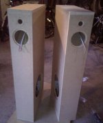
Cabinets will have a baffle width of 19 cm, overall depth of 44 cm, and a height of about 110 cm.
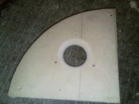
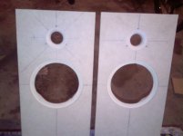
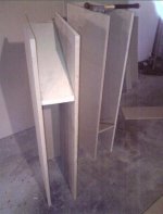
Standard symmetrical tweeter over woofer layout on the baffle, with the 10" woofer being side mounted. Midrange driver will be in an open back style enclosure, with the partition being on an upwards angle leading to a 40 mm terminus on the rear of the cabinet.
I am also doing away with the tweeters faceplate, and instead integrating the faceplate into the baffle.
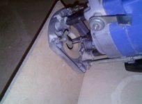
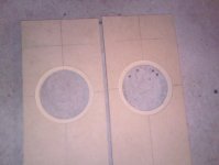
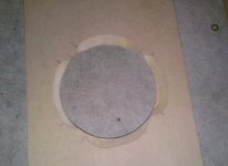
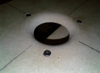
These are some pics of tonights progress, I made my own circle jig for the router from some 1/2" mdf sheet, and it works very well. I had ordered a Jasper jig, but it hadn't arived in time and since I paid an extra $20 in shipping to receive my order from Madisound in half the time, I wanted to start as soon as I could 🙂.
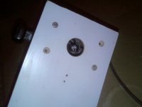
I also marked the location of the screws on the cutouts for the mids, and used an angle bit in the router to cut away material from the inside edge of the cutout.
I am hoping to get use of an air powered staple gun tomorrow to help with the assembly, otherwise will just use panel pins to hold it all together while the glue dries. Be sure to check back as I add more photos, and any comments or suggestions are always welcome 🙂
Driver compliment is Vifa D27TG-35-06 tweeters, Zaph Audio ZA14W08 midrange/upper bass and HiVi D10G woofers.
Cabinets will have a baffle width of 19 cm, overall depth of 44 cm, and a height of about 110 cm.
Standard symmetrical tweeter over woofer layout on the baffle, with the 10" woofer being side mounted. Midrange driver will be in an open back style enclosure, with the partition being on an upwards angle leading to a 40 mm terminus on the rear of the cabinet.
I am also doing away with the tweeters faceplate, and instead integrating the faceplate into the baffle.
These are some pics of tonights progress, I made my own circle jig for the router from some 1/2" mdf sheet, and it works very well. I had ordered a Jasper jig, but it hadn't arived in time and since I paid an extra $20 in shipping to receive my order from Madisound in half the time, I wanted to start as soon as I could 🙂.
I also marked the location of the screws on the cutouts for the mids, and used an angle bit in the router to cut away material from the inside edge of the cutout.
I am hoping to get use of an air powered staple gun tomorrow to help with the assembly, otherwise will just use panel pins to hold it all together while the glue dries. Be sure to check back as I add more photos, and any comments or suggestions are always welcome 🙂
Attachments
-
 Screen shot 2012-08-19 at 2.02.28 AM.JPG127.1 KB · Views: 931
 -
 Screen shot 2012-08-19 at 2.01.46 AM.JPG111.3 KB · Views: 889
 -
 Screen shot 2012-08-19 at 2.01.32 AM.JPG157 KB · Views: 866
 -
 Screen shot 2012-08-19 at 2.00.09 AM.JPG144.7 KB · Views: 860
 -
 Screen shot 2012-08-19 at 2.01.12 AM.JPG102.9 KB · Views: 843
 -
 Screen shot 2012-08-19 at 2.00.57 AM.JPG112.3 KB · Views: 209
 -
 Screen shot 2012-08-19 at 2.00.31 AM.JPG86.2 KB · Views: 224
Last edited:
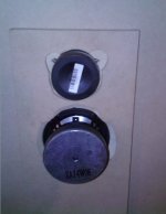
Right, made some more progress tonight. Started to assemble the main cabinets and partitions, and then did the routing on the baffles for the mounting of the tweeters. Took lots of measuring and double checking that everything would line up, and thankfully the extra effort paid off as the tweeter domes line up perfectly when the three screws are done up.
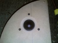
So instead of using the tweeters faceplate I used a spade bit to create a 32mm hole, then went around the edge with a 9.5mm radius roundover bit, to give a nice even flare and then from the rear I routed away enough material so that I could screw the magnet and diaphragm directly to the baffle, making it the nre faceplate. The result is not too far off the original tweeter and should help with dispersion, as well as looking way better (in my opinion).
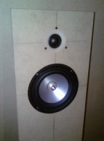
I also did a test fit of the drivers to make sure everything fits as intended, and it was a near perfect fit, so very happy with how things are going so far.
So instead of using the tweeters faceplate I used a spade bit to create a 32mm hole, then went around the edge with a 9.5mm radius roundover bit, to give a nice even flare and then from the rear I routed away enough material so that I could screw the magnet and diaphragm directly to the baffle, making it the nre faceplate. The result is not too far off the original tweeter and should help with dispersion, as well as looking way better (in my opinion).
I also did a test fit of the drivers to make sure everything fits as intended, and it was a near perfect fit, so very happy with how things are going so far.
Attachments
How did you calculate the box dimensions , did you use any modelling softwarwe like winsamp . Did you measure the T/S parameters or used the spec sheets provided by the driver manufacturer.. And why did u plan side firing woofer..it was for visual aesthetics or any acoustic benefits
Looking good. You using those D10G sealed then? They need a large volume for ported, but can play very nicely in a sealed box, WinISD suggests around 100 litres for each driver sealed, -3dB at around 40Hz.
Dr. EM, I am using a ported alignment for the D10G, and will be adding a rear port. I measured the specs myself for the driver, and they gave very similar results for the calculated box volume etc to the manufacturers specs. Ideal box was 120L or so with an f3 of around 25 Hz, but it had massive group delay on it and large phase distortion. After playing around I decided to reduce the box to 75 litres and raise the tuning point to around 33 Hz I think, as it gave huge reduction in group delay and less phase distortion. Sacrificing a few bottom notes for a better overall sound. The modelling programs just calculate the volume for maximum flat extension normally, but its not often the best sounding. And since response down to 30 Hz is enough not to need a subwoofer I think its a good compromise.
And to answer Akrambash, I chose to use a side firing woofer as it lets me keep the baffle narrow for reduced diffraction etc. As the lower frequencies are less directional, it can be acceptable to have the woofers on the side without affecting the stereo image etc (to a greater or lesser degree). I had a Dayton Audio WT3 for testing the Thiele-Small parameters (until it broke, grrrr) and I use bassbox pro for cabinet modelling, and sometimes winisd as a 'second opinion' 🙂
And to answer Akrambash, I chose to use a side firing woofer as it lets me keep the baffle narrow for reduced diffraction etc. As the lower frequencies are less directional, it can be acceptable to have the woofers on the side without affecting the stereo image etc (to a greater or lesser degree). I had a Dayton Audio WT3 for testing the Thiele-Small parameters (until it broke, grrrr) and I use bassbox pro for cabinet modelling, and sometimes winisd as a 'second opinion' 🙂
Last edited:
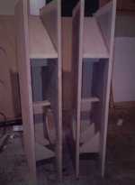
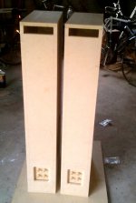
Some more progress on the cabinets, cut out the side holes for the woofers and installed the T-nuts, and also added cabinet bracing.
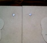
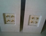
Also, on the baffle I countersunk the screw holes for the tweeter, and I have installed four small neodymium slug magnets in the normal place where you would install the mounting plugs for grille pins. I drilled the mounting holes from the rear of the baffle and left about 1-1.5 mm of wood at the end so that the magnets are very close to the front surface but there is no visual indication of them, then filled the hole with glue. These will be used later to attach the grille frames that will have small pieces of iron to line up to the magnets to give nice and tidy grille mounting, that you can't see when the grilles are off (inspiration for that idea came after seeing a similar mounting system on some B&W bookshelf speakers on demo at a local electronics store)
Also, on the baffle I countersunk the screw holes for the tweeter, and I have installed four small neodymium slug magnets in the normal place where you would install the mounting plugs for grille pins. I drilled the mounting holes from the rear of the baffle and left about 1-1.5 mm of wood at the end so that the magnets are very close to the front surface but there is no visual indication of them, then filled the hole with glue. These will be used later to attach the grille frames that will have small pieces of iron to line up to the magnets to give nice and tidy grille mounting, that you can't see when the grilles are off (inspiration for that idea came after seeing a similar mounting system on some B&W bookshelf speakers on demo at a local electronics store)
Attachments
Another update on the build. Construction of the cabinets is now complete, so now its time to start installing the drivers and electrical bits, and start working on the crossover. I am waiting for my new dayton audio DATS woofer tester to arrive, after my WT3 stopped working (grrrrr), to observe the systems impedance peaks to aid in crossover design.
Will try the woofers in a sealed setup, and then depending on how they sound may port the cabinet.
Will try the woofers in a sealed setup, and then depending on how they sound may port the cabinet.
Attachments
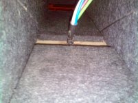
Today I lined the interior walls of the midrange enclosures with a dense felt-like absorbent material, which has really deadened the enclosure quite well. Before I installed it, I put my hand inside and snapped my fingers and it sounded quite bright and reflective. Afterwards it sounded much more dull with no ringing, and even talking into the mounting hole for the driver, it is very noticeably quieter and dead sounding.
No real surprises there, but it was quite surprising how well the material worked, and that;s just the wall lining.
No real surprises there, but it was quite surprising how well the material worked, and that;s just the wall lining.
Attachments
"I'm Late."
"I'm Late." ... "For a very important Date."
"No Time to say HELLO ...... GOODBYE..."
"I'm Late... I'm Late... I'm LATE." '
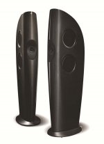
The KEF BLADE speaker is getting very good reviews.
The KEF BLADE engineering emphasis:
1) coherent mid-tweet source (coaxial used, but lambda/4 M-T also works)
2) reduced baffle diffraction
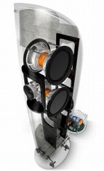
3) counter-force bass vibration control
Any diyAudio members thinking about a speaker similar to flyingtele might want to research the KEF Blade. Cardboard SonoTubes can be formed around wooden ribs to match the KEF Blade shape. There are a few baffle simulation tools that demonstrate the value of large radius diffraction management.
Reseach a few 8" coaxial speakers, as well as the small diameter SB29RDNC tweeter mounted RIGHT-NEXT-TO a wide bandwidth 7" midbass.
I like the RADIAN 508/2B
http://www.radianaudio.com/componen..._image/prod_files/Radian Audio 508 Polars.pdf
B&C coaxes 8CX21 and 8CXN51 are used by Tom Danley
BEYMA 8BXN also worth a look.
"I'm Late... I'm Late... I'm LATE." '
"I'm Late." ... "For a very important Date."
"No Time to say HELLO ...... GOODBYE..."
"I'm Late... I'm Late... I'm LATE." '
The KEF BLADE speaker is getting very good reviews.
The KEF BLADE engineering emphasis:
1) coherent mid-tweet source (coaxial used, but lambda/4 M-T also works)
2) reduced baffle diffraction
3) counter-force bass vibration control
Any diyAudio members thinking about a speaker similar to flyingtele might want to research the KEF Blade. Cardboard SonoTubes can be formed around wooden ribs to match the KEF Blade shape. There are a few baffle simulation tools that demonstrate the value of large radius diffraction management.
Reseach a few 8" coaxial speakers, as well as the small diameter SB29RDNC tweeter mounted RIGHT-NEXT-TO a wide bandwidth 7" midbass.
I like the RADIAN 508/2B
http://www.radianaudio.com/componen..._image/prod_files/Radian Audio 508 Polars.pdf
B&C coaxes 8CX21 and 8CXN51 are used by Tom Danley
BEYMA 8BXN also worth a look.
"I'm Late... I'm Late... I'm LATE." '
Attachments
@jacobthellamer
The deadening material I used was originally intended for use as pin-board material that also is used for sound deadening, such as on the walls of classrooms and meeting rooms etc. I bought a bunch of offcuts from a building supplies closing down sale, now that I have seen how well it works in speakers I'm annoyed I didn't buy more of it haha. Never mind, at lease I still have quite a bit left.
The deadening material I used was originally intended for use as pin-board material that also is used for sound deadening, such as on the walls of classrooms and meeting rooms etc. I bought a bunch of offcuts from a building supplies closing down sale, now that I have seen how well it works in speakers I'm annoyed I didn't buy more of it haha. Never mind, at lease I still have quite a bit left.
Some more progress, went and bought a bunch of fiberglass insulation and some polyfill to experiment with damping. I have a small amount of yellow fiberglass that came out of some old Philips speakers, and some pink home insulation batts. The pink batts seem to made of finer fibers.
I experimented with stuffing types and amounts in the mid enclosure first, and after each change I took an impedance sweep with my Dayton DATS woofer tester. In the first test I just had the woofer mounted in the cabinet with no stuffing, and there were two sharp impedance peaks, I imagine the first is the system tuning frequency and the second is the driver resonance (first graph).
After trying different styles of stuffing, I found that polyfill gave similar results to fiberglass but was much easier and safer to handle.
I found that light stuffing behind the driver, followed by as much stuffing I could get into the mid section and leaving the rear section (10 cm from the terminus) gave the bzest attenuation of the impedance peak and largely eliminating the second lower peak, leaving just a small hump on the lower side of the resulting peak, as can be seen in the second graph.
Any further stuffing toward the end of the pipe actually slightly increased the impedance peak.
The original plan was to have the woofer vented, but after some experimentation I will probably leave the cabinet sealed. By adding 25g of mass to the cone and filling the cabinet with fiberglass I am able to get an f3 point of 35-37 Hz which not far off what I would have got by venting the cabinet (due to its less than ideal internal volume) but with much tighter response. I lose a couple of dB sensitivity but the mid driver is 2-3 dB lower in sensitivity than the woofer so overall should all match up. Minor differences can be adjusted in the crossover to, and the tweeter will almost certainly need some padding on it so as to bring it in line with the mid and woofer. Next step will be to start taking acoustic measurements of each driver and determine crossover points and design the crossover.
Attachments
Finally had a listen to the speaker, using the impedance data that I measured I designed and built a crossover (just a prototype, used dirty ol' iron core inductors and electros) and tested it. Due to the value of some of the caps and inductors I will have to use ferrite cores for the larger values (12 mH) but will use polyprop caps and aircore inductors where possible.
Initial results were very good, bass was nice and deep, treble was clean and clear and the mids sounded quite neutral. A few anomalies that I will sort out, but given the components used in the test xover and not all were exact values, I only used what I happened to have, it sounds good and will only get better.
It has a surprisingly big sound, and although I was only listening to one speaker, it didn't sound like I was only listening to one speaker.
They suck a bit of power, but I was aware of that before the build due to driver choice. I crossed the woofer to the mid at 200 Hz, with a 6dB filter on the woofer and 12 dB filter on the mid, and crossed the mid to the tweeter at 3K, both with 12 dB filters. Woofer directionality is not an issue, I can stand 1m away at 45 degrees to the front so I'm facing the mid and the woofer, before I even notice any sound specifically coming from the woofer, as it blends very well with the mid.
I included fs and inductive impedance compensation on the mid and tweeter, and inductive only compensation to the woofer, and having listened to it with the impedance eq's in an out of circuit, they do make a good improvement.
Next step is to take some acoustic measurements, and include a 3 dB pad to the tweeter.
Attachments
Last edited:
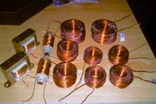
Spent this afternoon winding all the inductors for the crossover. There are 6 inductors used per crossover: 0.44 mH, 0.71 mH, 1 mH, 5 mH, 8 mH and 12 mH. Bought the copper wire from a local motor and transformer re-wind workshop, total cost for the copper is about $50, and to buy them pre-made would have cost in the vicinity of $250, so definitely a hugely worthwhile saving by making them myself.
All except the 8 and 12 mH inductors are air cored, and I wound these with 1mm wire. The 8 mH inductors I wound on some salvaged ferrite cored bobbins, and the 12 mH inductors were removed from an old Cerwin Vega subwoofer with a passive crossover and a blown driver, and I just removed windings until I got the correct reading on the meter.
Now I need to dunk them in some varnish for an hour or so to harden them up. The whitish areas on the coils are from where I applied small amounts of superglue, just enough to keep the windings in place and all them to be handled without falling apart and the white wire-wound resistor is just shown to give some sense of scale.
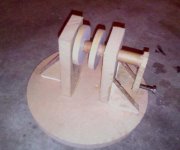
I made a winding system for winding the coils, with a hand crank handle, and the wooden disks have a removable pin through them and has 5 different width settings. After the coil is wound the pins are removed, and the centre spindle is pushed put from the end and the coil then carefully removed. Works very well and saved me a lot of time and sore hands.
More photos to come tomorrow as I make further progress.
All except the 8 and 12 mH inductors are air cored, and I wound these with 1mm wire. The 8 mH inductors I wound on some salvaged ferrite cored bobbins, and the 12 mH inductors were removed from an old Cerwin Vega subwoofer with a passive crossover and a blown driver, and I just removed windings until I got the correct reading on the meter.
Now I need to dunk them in some varnish for an hour or so to harden them up. The whitish areas on the coils are from where I applied small amounts of superglue, just enough to keep the windings in place and all them to be handled without falling apart and the white wire-wound resistor is just shown to give some sense of scale.
I made a winding system for winding the coils, with a hand crank handle, and the wooden disks have a removable pin through them and has 5 different width settings. After the coil is wound the pins are removed, and the centre spindle is pushed put from the end and the coil then carefully removed. Works very well and saved me a lot of time and sore hands.
More photos to come tomorrow as I make further progress.
Attachments
- Home
- Loudspeakers
- Multi-Way
- 3-way slimline tower speaker build, with photos