MTM Speaker drivers

Has anybody expirience with the 2 4 ohms midbass in Series, -and then in parallel with the High tone driver. I have bought scanspeak 18w4531G00 and R2904/700005 drivers too a very good Price and was told that this should not a problem soundwise but cant find Any exambles with this setup, or anybody with expirience in this setup?. I know It Will be 3 dB lover, that is not my problem. Thank in advance.

ZV7T : how to make distortion analyzer?

The latest Zen is Zen ver 7, common inductance loading. Mr. Pass said that this amp cannot be trimmed by matching voltage or matching current, it has to be done with distortion analyzer.
He said that we can also built (if cannot buy one), like the IM analyzer (Audio Express).
Does anyone has copy of that article? Or have other DIY distortion meter that can be used for trimming this amp?

Simple SE Amplifier

I realised that I have never hear the sound of a single ended tube amplifier, never tried to build one, therefore decided to put together a proof of concept, very simple and on the cheap.
Goals:
1) Use tubes that I have, nothing fancy. I got some 6P41S and 6N1P tubes.
2) Output power 10W (AVG), no gNF, only local feedback, less than 3% THD.
3) Cheap output transformer from China, 3K3:8ohms, 15W (claimed)
4) Use cheap SMPS for power supply.

The schematic is very simple, just 1/2 6N1P input stage and two 6P41S in parallel, self-bias, class A only, no g1 current.
I was a bit surprised that it actually works quite well, I get around 10W before clipping starts due to g1 current, but this is enough to drive my Monitor Audio Bronze BX5 speakers. Also, there is zero hum on the speakers with the volume tap at max.
The bass is not as strong as in my push-pull amp, probably could do with a better OPT, but Pavarotti, Il Volo, Aretha Franklin all sound great.
Here are some pictures, improvement suggestions are very welcome. I'm planning to add a Mosfet to allow A2 to see how much power can I get without too much distortion. I will also do some more precise distortion and bandwidth measurements, I'm interested to se how good (or bad) the OPT is.

IMG_20220418_134208.jpg
SE_2x6P41S_6N1P_InputStage.png
IMG_20220418_134229.jpg
IMG_20220418_134243.jpg
IMG_20220418_134610.jpg

Eminence 10CX Build

Eminence 10CX build.....Wired the High Pass filter to the back panel switches, cut the bass port on the back panel and installed the port. Screwed the back panel on......Initial impressions.....Very "Klipsch Like", very efficient, good bass, lively sounding speakers......More listening and testing.....More to follow

Attachments

  • P1050348.JPG
    P1050348.JPG
    332.5 KB · Views: 107
  • P1050349.JPG
    P1050349.JPG
    401.1 KB · Views: 119
  • P1050350.JPG
    P1050350.JPG
    290.8 KB · Views: 121
  • P1050351.JPG
    P1050351.JPG
    352.4 KB · Views: 126
  • P1050352.JPG
    P1050352.JPG
    232.5 KB · Views: 124
  • P1050353.JPG
    P1050353.JPG
    280.7 KB · Views: 125
  • P1050355.JPG
    P1050355.JPG
    528 KB · Views: 112
  • P1050356.JPG
    P1050356.JPG
    390.5 KB · Views: 103
  • P1050357.JPG
    P1050357.JPG
    400.9 KB · Views: 99
  • P1050358.JPG
    P1050358.JPG
    380.8 KB · Views: 103
  • P1050359.JPG
    P1050359.JPG
    493.4 KB · Views: 112
  • P1050360.JPG
    P1050360.JPG
    451.3 KB · Views: 117

Testing newly built mullard 5-20

I've confirmed that the voltages are good and there are no shorts or obvious wiring faults. During this test, there was a moderate amount of buzz and hum and my 8 ohm dummy load got very hot. I disconnected it and left it as I didn't have all of the test gear on hand and it was late.

I've rerun the test this morning with a scope across the output and this is what I got. 39Hz square wave at 47V p-p.
An externally hosted image should be here but it was not working when we last tested it.


This has been built to a different layout which I feel may be a contributory factor but otherwise, I've made no other modifications.

I'm a little baffled as to the likely cause.

LM1875 output circuit

I have built an LM1875 based amp more-or-less using the TI data sheet circuit for dual rail which does not have any capacitor in the output (between pin 4 and the speaker). Before connecting to speakers I measure 5-7VDC between pin 4 and ground and if I measure the current it shows about 1A. I am using 8ohm resistor as bench load whilst testing and notice (naturally with 1A) significant heat.

Is it required to put a 2200uF (seems most common value) or not in the output, if not, why might I see this voltage, and the fact that I measure 1A current its not a phantom or floating voltage.

Also I see some circuits with a 1 Ohm and series 22nF cap to ground, seems this improves stability? Correct? Required?

The DC split rail is 24-0-24V DC.

Any thoughts or guidance. I have powered for short periods so far.

Sony MHC-C305 CD tray does not eject

Sony mini hi fi mhc-c305. CD drawer does not open and CDs do not play. I have set function to CD. All lights indication CDs in trays are on. Open close does not work, but things do move inside when pushed. I tried a hard reset (by disconnecting the Sony from power (with the unit turned ON), then press and hold the power button for 10 seconds and release. Wait 30 seconds or more and plug the system back into power, turn it on and then press and hold the Eject button for 15 seconds or until the tray opens- whichever comes first). The tray still does not open. All other units on this stereo system work. I put the unit into dry storage a few years ago and at that time it was in full working order.

A simple LT1763 based 5V PSU

I'd like to design and build a simple low noise 5V power supply based on the LT1763. I've made a schematic and layout, does anyone have any feedback or suggestions for improvement?

TR1: Pads for Block FL2/FL4/FL6/FL8 or EI38 or EI30. Ideally 2x 6VAC.
B1: VISHAY DFL1508S bridge rectifier
C1: Panasonic FC 1500UF, 16V
C2: 100nF X7R
IC1: LT1763CS8-5, 5V fixed regulator
C3: C0G/NP0, 10NF, 100V
C4: Panasonic FK 100UF, 6.3V, SMD
C5: 100nF X7R
R1: Resistor for LED
LED: 1206 LED

Should I add a coil before the regulator? A snubber might be a good idea but I don't have the equipment to take measurements for this.

Attachments

  • 5VPSU-layout.jpg
    5VPSU-layout.jpg
    457.5 KB · Views: 1,487
  • 5VPSU-schematic.jpg
    5VPSU-schematic.jpg
    93.6 KB · Views: 1,665

[Sansui A-900P] not working, high voltage on transistors.

Howdy!

I'm relatively new to the world of fixing amps but I have already restored Pioneer SA-508 and Marantz 1040. However, third time is definitely not a charm. <:

I recently bought Sansui A 930P, not the best shape but externally I'd give it 6/10 can be polished and detailed though to make it 8/10. Coming to the point, though.

The aforementioned amp did not work when I bought it. It turned on, but no speaker noise, cracking, nothing, nothing on neither channel or selector. Well the selector itself didn't really work, pressing the buttons caused the buzzer to beep but no LED was being lit.

I started investigating and now I have it in pieces, the main board is the one that's giving me problems. There is some weird voltage on transistors but I can't really get what's going on. I checked all the trans and they seem to be ok, no short circuits. I've also checked other main components (resistors, caps, chips) and they seem to be ok as well.

The problem is that sometimes on the transistors I have 50v on all three legs BEC, the thing is worse because it sometimes is left, sometimes right channel. I tried to bend the pcb, tap the components... no place which would change anything. The only reaction was while spraying IPA on some of the components. However, not always and not repeatable, I cannot replicate the change of the channels. I don't have a clue what might be causing it. I even had 50v on all 3 transistor connections with NO transistors being present in that channel.

If anyone wants I can post photos or service manual for this model.

TIA for any suggestions,
mistahke

Ciao a tutti

Good morning everyone.

My name is Luca and I write from Italy, precisely from Liguria.

I have a small plant consisting of the following components:
  • self-built t-amp
  • a Madison MAD-TA10BT integrated that was given to me.
  • a preamp built on a kondo M77 base (it works but I have to build the case)
  • a pair of wharfedale diamond 9.1 speakers.

I'm also building an EL 34 PP amplifier based on the Radford Sta-35 schematic.

I joined this forum to learn new things and get inspired.

IWT Buy or Borrow: 18 Sound 6ND430 for testing

I want to borrow one, or buy used a pair, of these cuties:

6ND430.jpg


I am currently trying out a number of drivers as midranges in an open baffle system that I am putting together. The 18 Sound 6ND430 is a proven driver. Zaph tested these a few years ago and the data looks great, but it doesn't tell me what I need to know for use in my system where the driver is suspended in free air by wires (a nude swinging dipole system if that is a familiar term for you).

I would like to get my hands on one of these driver so that I can hang it up in free air and do off axis measurements in front and to the rear as well as distortion under these conditions. Since these drivers cost $150 each I am a little hesitant to buy a pair for these tests.

If I could borrow one driver that would be the best scenario. I would pay shipping both ways.

I would also be interested in a clean, used pair if the price is right.

I live in N. California, shipping from nearby would be preferable.

Please contact me if you can help me out. Thanks!

Euro / USD getting interesting...

Don't know about all y'all, but for those of us in the states looking for favorable currency rates to buy up NCore modules...new NC400 are now around $300 USD/each + ship...never seen them so cheap new...

I guess I never knew the Euro and USD haven't been equal for over 20 years...but getting closer...now at $1.05 USD/Euro. Approaching the lows of 2002 at $1.02 USD/Euro. A close under $1.02USD could see the Euro fall all the way to .85 USD/Euro...wow...back up the truck to buy NCore modules, or anything else in the EU if that happens!!!

https://www.dailyfx.com/forex/techn...eing-2017-Bottom-After-Clearing-2020-Low.html
  • Like
Reactions: vincepgh

Thermistor (NTC) needed. R25=465 Ohms, NTC=-1.48Ω/K

My new version of the VBE multiplier requires temperature sensing using an NTC thermistor with a resistance at 25C of 465Ω and a temperature coefficient of -1.48Ω/K. My first impression is this may be impossible to find, which means, additional circuitry is needed to emulate this behaviour using available NTC thermistors. The major problem is the operating voltages are below 1V. A BJT transistor used for emulation will not solve the issue as BJTs exhibit a constant resistance below saturation. A transistor is needed which should work under 1V and provide a resistance that is dependent on an input signal.

Aternatively, a network of different NTC termistors may be created to emulate the required behaviour. I am looking at this solution as this provides an average of temperature and an effective resistance which should be more realistic.

CD player laser diode replacement

Hello everyone here! Thanks for adding me to this great community!!
I would like to make a question,
Firstly, sorry if this has already been answered here.
I am trying to restore some vintage cd players but I have problems with optical pickups (most of them are not available any more). So, I was wondering if it is possible to replace the laser diode itself, not the entire pickup. The problem is, that after diode replacement the laser beam fails to locate in the middle of the photodetector IC (also known as PDIC). This IC has (in my case) six photodiodes, named A,B,C,D,E,F. The main beam uses the four(A to D) lacated at the middle, while the side beams use the other two (E,F). How can I align properly this IC in order to pinpoint the main beam into the center?
Any help is greatly appreciated!
I am hoping that some cd gurus are still available here!
Thanks,
Kostgeor

Attachments

  • Configuration-of-DVD-laser-head-Fig-2-a-Mechanism-of-VCM-b-System-dynamic-model.png
    Configuration-of-DVD-laser-head-Fig-2-a-Mechanism-of-VCM-b-System-dynamic-model.png
    20.5 KB · Views: 583
  • c8z88zwyqfz41.jpg
    c8z88zwyqfz41.jpg
    33.2 KB · Views: 580

Charlize, my thoughts

Okay,
I got my Charlize (air core inductors) and Monica about 2 weeks ago and have just got around to trying Charlize last night.
I built a quick Corian and Aluminium chassis for temporary use. I am using a Nad cd player and Jerico horns with Fe208 Sigma’s and a homemade FVP5 pre.
Charlize is battery powered. a 12V (12.7V) 9AH unit from a UPS, no caps or anything else.
Thoughts after only ~1 hour.
WOW.
The first 20 minutes were harsh but it suddenly cleared up and seems to have progressively improved for the short time it was on. While I did not compare to anything else last night I was impressed, clear and lucid, a bit forward sounding (but I like that) plenty bass (maybe too much) great separation and as others have said it almost makes a piano sound like a piano, great decay. Not at all strident like many a SS amp, more smooth.
I keep looking at this little board and listening to it and am bewildered, my prejudice is showing, its too small and cheap to sound like this!
When I consider that this amplifier costs about the same as a decent power transformer for a tube amp and its already built .....
Not all is well though, there is that turn on thump, very frightening seeing my drivers extending like that, I know that there is a fix for that but think it should have been incorporated into the design. I tried the separate switch for the mute but it made no difference.I am picking up a touch of R.F. but only in the left channel and it is very, very slight, I thought it may be because of my chassis but since its only the Left channel I doubt it but will know for sure when the permanent case is built. I only noticed it because I was listening to see how much noise if any the amp produced with my ears against the speakers, the noise is minimal and my speakers are very efficient so I consider the noise to be a non issue. I was also wondering is perhaps there may be a bit a bass lift in the ~ 50 -80 Hz range, maybe to help smaller speakers?
I am certainly looking forward to hearing this after a few hundred hours to see if I still enjoy it as much, or more.
I am presently trying to work out the conversion of a PC power supply to power it as Nuuk feels the SMPS is even better than a battery.
Hey Yeo! Nice job, Charlize should keep you and your partners busy, I may hit you up for another one, want to buy a tube amp or two?


Andrew

Genelec 8240A loud Buzzing noise

I have two Genelec 8240a monitors that started to generate a loud electrical buzzing noise.
This is on both monitors after powering them up during warm-up period. After 2-10 minutes the noise disappears and they operate as normal. I normally leave them on 24/7 and they have worked fine for months, but now one of the monitors suddenly generate noise for 30 sec to 5 minutes when warm.
I'm betting one of the capacitors gave up, but does someone know which to change?
The noise is generated internally without anything connected. Same noise with analogue or digital source.

The attached sample is when powering up the monitor.

Attachments

Hammond H-AO-43-1 (L100) chassis of any merit?

The Zenith amp project is wrapping up, so time to plot the next move.

I have here what looks like a pair of twin Hammond H-AO-43-1 organ reverb / power amp chassis. Each unit has power, output and reverb transformers plus six sockets - 1X octal rect. plus 5X 9-pin sockets. Two of the latter are for EL84 / 6BQ5, with the remainder taking 2X 12AX7 plus one 12BH7. I believe the 12BH7 is part of the reverb amp / driver.

The web says folks have made guitar amps out of these, reusing the extant reverb xfmr with a (generic?) spring tank. That might be of interest, if I could play anything other than the stereo.. so for my money, they should become audio monoblocks. But that's not one conversion I've found, at least not so far - but it cannot be uncharted territory.

So what should be done with them? Pull the xfmrs for other chassis, or build on the stock chassis? I'm all for the latter, naturally. What say you all?

hammond H-AO-43-1.jpg

Where to find a remote activated 12v trigger relay?

My mono block amps have 12v trigger inputs to connect to another device to receive a signal to automatically power themselves on upon another device being powered on. Unfortunately none of my other audio gear has 12v trigger outputs. So my question is where can I find a gadget with 3.5mm outputs that will send out a 12v signal to my amps upon itself receiving a signal from a remote?

Currently I own this device but it too requires being sent a signal to be able to send out a 12v trigger signal: Amazon.com: Emotiva Audio ET-3 Wire Management: Home Audio & Theater

Any help is greatly appreciated. Thanks.

Low value fuse DCR concerns

I am repairing a tube amp & there are fuses in the bias ckts. for the power tubes. (KT88s) The fuses (125mA) that survived the failure measure 3.4 ohms & new fuses measure 6.6 ohms. BTW I measured the fuses with a 22 ohm resistor in series. I don't have instructions for adjusting bias on this unit & am concerned about replacing some fuses with these new ones. I didn't notice, when I ordered the fuses but, is the DC resistance in the spec? So, should I be concerned about this variance (3.2 ohms) in the new fuses?
Thanks,

Mains, sub filter

Filter

Hi all. I have posted some requests on this site for help I think only on person bothered to assist some. I have another query to the members here in case someone is inclined to help with this one

I am looking to build this filter but I need some help in determining the filter point. I need a filter point of around 200-300hz. This is for a boombox type ting

Thanks and regards
Randy

3 Phase BLDC motor for turntable use?

I've been kicking around the idea of a 3 phase BLDC motor and controller for a couple of years now. I've experimented with a lot of the Hurst AC synch motors, but vibration was ALWAYS a problem. I found the Hurst motors to be very inconsistent in build quality. Problem with the BLDC approach, I could never find a motor that I liked or that was cost effective, until a recent trip to Japan when I found a fantastic 3 phase BLDC motor in the Akihabara electronics mart. Inspired by a couple of conversations with Mark Kelly on the subject, I finally decided to pull the trigger on the controller now that I found a suitable motor, mainly as a non-commercial project-- just to see what was possible.

The motor is 24V / 12W / 1500 RPM and has about 4x the torque rating of a 10W 600 RPM Hurst AC synch motor, although it is smaller diameter (45mm vs 59mm) and only slightly longer (60mm vs 40mm). When I spin the motor by hand, I feel no cogging at all, even though it has iron stators and a PM rotor. The motor uses precision ball bearings that are pressed onto both ends of the shaft so there is no end play at the pulley at all. I think this is one of the reasons the Hurst motors are so noisy; that and they only have one bearing at the top of the shaft, the magnet/rotor is left to fly around at the bottom with no support. I've built 2 phase controllers for the Hurst motors, but of the 6-8 motors I have, not all of them would work; some of them would start vibrating horribly as they got up to speed unless I damped the motion with my thumb. I contacted Hurst about this and they said that was typical and that I should attach a small collar to the shaft to control end-play like VPI does on some of their motors. Didn't seem like a very workable solution to me. The bearings in the BLDC motor initially gave me pause, until I fired it up and realized it was far quieter than any of the Hurst motors I have. The construction of the stators is similar to AC induction motors with all of the windings on one core assembly rather than on 2 bobbins like the AC synch motors (another source of vibration in the latter). The BLDC bearings are sealed and never need lubrication; and unlike friction bearings, they can handle much higher radial loads without having to replace them when they wear. The motor runs quieter than any of the Hurst motors I have and is comparable to the 2W Premotec motors for noise.

The controller is the same basic design as my other controllers (DDS based) except that it has 3 phases instead of one. I also needed to adjust the output voltage and phase based on the speed of the motor and the torque required. Having independent control of all three elements creates an extremely smooth rotation with much more torque than an AC synch motor. The other HUGE advantage is the range of speed control with this method: With the Hurst AC synch motor, I would be lucky to get 3:1 speed range, even when driving both phases with quadrature signals. The high end (90Hz max) would have almost no torque and the low end (30Hz) would cog excessively. With the BLDC motor, I can easily get 100:1 speed range running the motor from 15 RPM to 1500 RPM (<1RPM to ~83 RPM at the platter) and the torque is surprisingly high even at 78 RPM. I start the motor at ~5Hz (4.2 RPM at the platter) and can ramp up to 93.6Hz (78 RPM at the platter) in a matter of seconds with zero burn out on the belt and all 3 speeds (33/45/78) using the same pulley. The controller drives a 3 channel class D amp powered by a 24V 1A wall wart. The amp fits in the same sized housing as the controller (about the size of a pack of cigarettes) and never gets over 100 deg F.

Since I have complete control over the phase of the 3 windings, I can also control the direction of rotation in software. I can easily switch between CW rotation for belt drive or by putting a rubber grommet on the pulley and switching to CCW, use it as a direct rim drive. I had a local machine shop turn an aluminum housing from a piece of 3.5" solid aluminum bar; the standard SAMA housing on my Scout was too wide to allow the motor to get close enough for the pulley to make contact with the platter. I wasn't happy with the vinyl grommet so I stuck with belt drive for now, but I'm going to keep looking for a softer silicone washer to use for rim drive.

I did some listening tests with the new motor vs the Hurst AC synch motor on a VPI Scout table and there is a noticeable improvement. Dynamics definitely took a step or two in the right direction. Because the motor has virtually no vibration, the noise floor seems to have dropped as well and the back ground is eerily quiet. Detail and clarity seems to have improved, but only because they don't get buried in the noise as before. I don't think it change the sonic signature of the table, the detail was always there, I just couldn't hear it as well. I wished I had found this motor earlier, but now that I have it, I'll never go back to AC synch motors again.

Attachments

  • CTRL-AMP.jpg
    CTRL-AMP.jpg
    250.1 KB · Views: 3,152
  • MOTOR1.jpg
    MOTOR1.jpg
    203.3 KB · Views: 3,073
  • MOTOR2.jpg
    MOTOR2.jpg
    208.2 KB · Views: 3,198

Member requests help designing Capacitance Multiplier for Class A amplifier

I received a Private Message from a diyAudio member, containing this request. Since I believe that ten thousand heads are better than one, I'm posting the request here in the Forum, to access the collective wisdom and insight of everyone here on diyAudio. Please assist this member if you're able. Thanks very much --MJ

I wish to make a cap multiplier for class A amplifiers.
I found various attempts in this forum and decided to focus on Smooth Like Butter cap mux, based on Complementary Feedback Pair configuration [aka Sziklai]. (LINK) In that thread I saw posts about the possibility of CFP oscillations, and I am concerned that it might be serious.
Can you please suggest a good yet oscillation free Cap mux? Or help me to refine the SLB with components for making it more stable? I noted the following:
1. Ballast resistor in the emitter of main pass transistor -- 0.33R is enough?
2. The expression "gm degeneration" was mentioned, but I didn't understand.

Attachments

Cap Value Recommendation for a 2 way

I'm going to build a clone of the Decware DM945 and am looking for recommendations for the 1st order xover cap. I'm going to use them with my Decware Taboo MKIII

I'm going to use the 8" Silver Flute woofer and The HiVi tweeter.

https://www.madisoundspeakerstore.com/approx-8-woofers/silver-flute-w20rc38-04-ohm-8-wool-cone/

https://www.madisoundspeakerstore.com/ribbon-tweeters/hi-vi-rt1c-a-isodynamic-tweeter-120mm-94db/

.8cuft box with a 3" x 7" port

Any suggestions would be appreciated.
Thanks

Suitable speakers

Hello,

Recently I completed a 100WRMS per channel amplifier using parallel of two LM3886 for each channel. At the moment playing with some cheap speakers. I started the project with very little expertise in audio electronics, although I am an electronics hobbyist for a long time. Now I need some hi-end speakers
for the above amplifier. I have almost no idea about speakers, building one is a distant dream (this was also the case when I thought of building the amplifier, but thanks to diyaudio.com I could do this). I am searching the net for speakers, there are several with very good reviews (like Wharfedale Diamond 9 series etc), but the price tag is a bit too much for me. If there is no better (price wise) option without compromising on the quality, I may have to go for this.

Can someone help me? I need two-way speakers. I may consider building one, if it does not take too much time.

Best regards
Roushon

Style JCM800 diode clipping

Hello ,, I have a clone of jcm 800 2204 and I want to add more gain .. and I see the 2205 and 2210 jcm800 have diode clipping , so I want to add some diodes … check please my schematic .. is correct to make this with 2x 1N4148 silicon ? Thank you . The first pic is original schem. And the 2nd is my thought. Is correct ?

Attachments

  • 6B8C7CE7-2FDC-4BC6-8762-51AB40C02DEC.gif
    6B8C7CE7-2FDC-4BC6-8762-51AB40C02DEC.gif
    239.3 KB · Views: 1,010
  • A10475ED-C799-428B-90B7-24A341F52E2C.jpeg
    A10475ED-C799-428B-90B7-24A341F52E2C.jpeg
    181.5 KB · Views: 1,366

The malady lingers on

Well, my love for the JVC VFET continues. As one does, I occasionally punch in "VFET" while on ebay, and a few days ago something surprisingly appeared.

Without labouring the story, I am now the owner of a rather tatty and faulty Yamaha B2. It's a 100 volt model ex-Japan. The owner tells me that he turned it on one day and it emitted a weird sound, followed by a puff of smoke. Believe it or not this encouraged me to buy it, because VFETs are unlikely to emit smoke when they expire and I suspect either a power supply cap or, in the worst case, one of the power transformers.

Since the darned thing weighs in at 26kg (putting even the JM-S7 to shame) and I live in the country where couriers fear to tread, I'm having it delivered to my brother in Queensland. I need to visit soon to pick up a VW Transporter van that has been sitting in his yard while we've all been locked down by Covid. So it will go in the back for the return journey in a few weeks' time.

I'll let you know how the repair progresses and, if it can be made to work, how it compares to the JVC amp. In any case, at AU$500 it was a no brainer.

Edit: Forgot to mention, I checked to ensure it wasn't a dealer offloading an impossible repair. The seller also had a pair of Yamaha speakers and a 240-100 V stepdown transformer for sale, and he lived in a rather exclusive suburb, so that had no odour of fish at all. I think this one's a safe bet.

Attachments

  • My B2.png
    My B2.png
    326.8 KB · Views: 182
  • Like
Reactions: ranshdow

CMRR in a tube differential stage

Hello,
I'm wondering how a differential stage -like a LTP for example- handles noise. What theory predicts about CMRR assuming ideal implementation. PSU ripple should be perceived as common mode and rejected, or not? But what about heaters injected noise or EMI from transformers? What is common mode and what differential regarding noise sources in a case like this?

Two LM3886 in parallel w balanced/unbalanced preamp

Hello everyone!

I decided to move this project discussion into a separate thread.

LM3886 is a great amplifier chip that I knew about for a long time. And since I have some extra time right now, I decided to get back to it and finally build an amplifier. I have had four of those chips laying around since 2016.

The project has two boards: one for the preamp, and the second one is for an amplifier. Boards are designed to be used together.

What I think is so cool about this project:

For power amplifier board:
- Output power is 100W into 4 ohm and 60W into 8 ohm
- Can be powered with +-35V with the amp connected to the 4 ohm load
- Two chips are used in inverted mode
- DC servos to correct for any DC offset on the outputs

For preamp board:
- Preamp has two input levels: +4 dBu (XLR and TRS combo connector) and -10 dBV (RCA phono connector)
- Input sources can be switched with a push switch
- Instrumentation amplifier for balanced inputs
- Low noise buffer amplifier for unbalanced inputs
- Can be switched to +-17V or +-15V power via 3-pin header placed on the board
- LM317/LM337 regulated power source - can be powered with a wide variety of voltages (~18V - 40V)

Attachments

  • sch.PNG
    sch.PNG
    69.2 KB · Views: 218
  • sch.PNG
    sch.PNG
    28.1 KB · Views: 223

FS SB Acoustics Satori TW29BN-B-8 Tweeters

One pair of SB Acoustics Satori TW29BN-B-8 tweeters for sale. These are the famous beryllium 8 ohm version of this tweeter. I bought these new from Madisound ($406.50 ea.) and owned them for about 2 months. They have about 5 hrs of use in a project I decided not to proceed with - but they sound fantastic! Never driven hard or abused in any way. I did mount them and soldered the terminals, but otherwise they are 'as new'. Check out the photos.

Yours for $250 each! Will guarantee they are as described.

Attachments

  • TW29BN-2.jpg
    TW29BN-2.jpg
    71.9 KB · Views: 141
  • TW29BN-3.jpg
    TW29BN-3.jpg
    54.8 KB · Views: 78
  • TW29BN.jpg
    TW29BN.jpg
    57.8 KB · Views: 278

Solen Cap Damage - Help

Hello everyone,

I’m updating the resistors in the crossovers of my old DQ10 speakers and in the process, I accidentally singed the side of an Solen MKP capacitor. The damage is enough that it compromised the black outer shell enough that you can see the white polyester. I’ll try to include a pic. I have no testing equipment, but, am wondering if anyone else has experienced this, whether or not I should be good to go?

Any and all info appreciated.

Thanks,

John
0839ADC3-2CC5-4A6F-A3B9-C738E4BC4585.jpeg

[Europe] FS UltraBiB w/ parts for 5V

Hi there,

life being what it is I will never finish this UltraBiB. And its 2 year old cap should not wait any longer to be used.
What you see is what you get, give a decent price, we'll check the cheapest secured shipping and it'll be yours. (The Nichicon audio cap is not soldered, it will be packed flat for shipping).

Thanks
Matthieu

Attachments

  • UltraBiB.jpg
    UltraBiB.jpg
    449.3 KB · Views: 167

Telling apart home theatre vs component car drivers

I got a unbranded 6.5" woofers labeled "home theatre oem replacement midrange woofers" from a local electronic repair shop. $23 each came in 4 or 8 ohm. 2weeks later I saw woofers are also sold as replacement cars woofers (only difference was that it was sold as a pair and came with some mounting brackers) .


Most sources say not to use car parts in home speakers and vice versa... How can I tell if these are actually car or home speakers ?
At this price point, is there even a difference between component car vs stereo vs home theatre woofers, tweeters, etc. ? (t/s parameters seems similar)


checking Parts Express to see other options, the budget options there have the same issue.
ie Pyramid Pyramid W64 6.5" Midbass Woofers Some sites use them in home cabinets, more often they're used as car speakers.
They have 6.5" stock woofers that come in Dayton B652 for $7 are these actually going to sound better in home theatre build than $50 car midrange. woofers?

Improved 2W current sources (II)

Some improvements to the basic CCS's have been described here:
http://www.diyaudio.com/forums/solid-state/173005-improved-current-source-sink.html

Here are some further circuits, a bit more complicated but having a very wide compliance.

On the left is the basic circuit.
The performances are already quite good, with a variation of 0.25mA (for 10mA nominal) for a voltage swing of 2.5V to 62.5V.


The middle circuit has two improvements: the 22Meg, to avoid relying on leakage currents for start-up, and a 300K compensating resistor decreasing the delta current to ~25µA, 1/10th of the initial value.

If the tempco of -0.3%/°C is problematic, each pair of silicon diodes can be replaced by an LED, providing a first order compensation.
The circuit on the right uses the infrared LEDs of an optocoupler to minimize the working voltage.

Attachments

  • Hiperf2Wccs.GIF
    Hiperf2Wccs.GIF
    62.4 KB · Views: 2,475

Help with Femm files on github

Hi all
I am desperately needing some expert help.
I have been going through an old thread “project Ryu” on field coil drivers. Simulation file links were posted bu “Hentai” on the forum on Github for use on Femm.
I downloaded the files and imported into Femm, but after inputting the parameters it asks for, just gives me error messages.
I am desperately trying to simulate a field coil motor for my Lowther EX4 but am now stuck.

Would anyone be kind enough to guide me through this process (I am not a software Fundi) or simulate it for me with the EX4 specs so that I can get the required dimensions. I am fine with metal work and have access to top notch equipment.

Any assistance would be utmost appreciated.

Kind regards

Hafler xl-280 cap replacements

Hi all,

Not sure if I am in the right forum, but here goes...

Recently came across a pair of Hafler xl-280 in pretty good shape. One bad on / off switch (now replaced) and original owner removed speaker fuse holders (may or may not live with that)

Considering cap replacements. Especially the cans.

Presently using Mepco 3186DE782UO75BJA2. Seem to be original. Can purchase these - https://www.tedss.com/2020087692 or these - https://www.ebay.com/itm/142459354783 which I am sure are exact replacements, but are of unknown age.

Any idea where I can get an equivalent (or better) of a more recent vintage?

Thanks.


Best Transistors at Each Amp Stage

This was a great thread on output BJTs:
https://www.diyaudio.com/forums/sol...istor-families-audio-power-output-stages.html

Has anyone done a similar post on transistors for drivers, VAS, or input pairs?

Back around 1990, I used 2N2920 and 2N3811 matched pairs for inputs, but those are obsolete now. I'm looking at the SSM2212, but I'm wondering about it's performance above 1 mA. The datasheet graphs stop at 1 mA, but the device's ABS MAX for current is 20 mA. I used to run the 2N2920 and 3811 pretty hot. I had little starburst heatsinks on several of them.

I'm looking at BC847/BC857 for a lot of low volt general purpose mirroring and buffering around the amp. Some MMBT5401 and MMBT 5551 for high volt support circuitry. I'm looking at KSA1381 and KSC3503 for VAS, high voltage cascoding, and predrivers. Not sure that's the best choice, but I think it must be close to the best.

I'm looking at MJE15032/33 for drivers. I'm not sure these are the best, but they look good enough. They've been around awhile.

Anyway, I hope this will generate some discussion.

Pros and Cons of Spindle and CD moving on a motor-driven Sled (Sony CDP-XA Series)

Typically, a CD is spun in place, while a laser assembly tracks the recording (mounting on a moving sled).
Inside of several models of Sony's CDP-XA series the laser pickup is fixed (unusual) and the spindle and rotating CD move on a motor-driven sled.

You can see this mechanism in operation the first time you open the CD-loading tray: The latter moves outward at a different rate than the spindle itself - go to
http://blog-imgs-58.fc2.com/s/a/n/sanchopanza/20130509001.jpg
http://ns.tachyon.co.jp/~sichoya/main/corner2/lcxo01/11.jpg

Are there special benefits in opposite of mostly to find sled with moving optical pickup and fixed turntable motor ?

Thank you for your advices.

Please critique my TSE choke-input PS sim

Hello

I have a TSE PCB which I snatched up before George ran out for the re-design and I would like to build a choke-input power supply for it.
I plan on running it with 45s, so my B+ goal is roughly 300V @ 100mA.
I plan on using the 260-0-260 taps of "Universal" Tubelab Edcor power transformer (edcor xpwr131) with a stated secondary DCR of 70 ohms end to end (35 ohms from CT), per a thread here.

For the PSUD sim:
260VAC = 520pk-pk= 372Vrms. [Edit: 520*.707= (approx) 368Vrms]
I'm dividing the 300V B+ by 90mA ("rounded up" sum of currents to power and preamp tubes through B+) to get the 3.3K Ohm value for R1.


L1 is spec'd for a Hammond 159Q
L2 is spec'd for a Hammond 159S

Soft-start is disengaged for the sim.

PSUD isn't giving me any warnings but I would still appreciate it if somebody more versed in this could check my work.

Thanks in advance.

Attachments

  • PS45SET.PNG
    PS45SET.PNG
    361.5 KB · Views: 275
  • PS45SETclear.PNG
    PS45SETclear.PNG
    259.2 KB · Views: 318

Philips FR 320

Hi,

I took my very old Philips FR 320 amp receiver from 3000 Km away, just to find it doesn´t work.

When powered on the lights turn on, the tuner screen readings change and so.
But there is no sound coming out from the speakers, nor from the headphones when plugged.

There´s plenty of capacitors that are maybe dead, plus they are not easily accessible. Since I took the effort to move with me I thought I would at least ask if anyone has any advice to revive the amp.

Any suggestions/hope for this device?

Thanks in advance.

Schema

4.jpeg


3.jpeg


1.jpeg

Potting a choke input choke, beeswax or epoxy?

I'm making a low current, 50ma normal, 80ma max, choke input power supply using an open frame 10H 100ma choke (Hammond 158M), tube rectifier, 40uf after the choke. I want to cut off a 3.5 inch length of rectangular steel tubing I have, mount the choke inside then pot it. Then fabricate end caps from sheet stock, sand and paint, then drill and tap four M4 mounting screw holes.

Should I use beeswax or this electronic epoxy?

below is a photo of the tube stock I have, beeswax and the epoxy all of which I have on hand. I'm leaning toward the beeswax myself, I have a hot plate in my shop, just melt it and pour. I'm afraid the epoxy would be too hard and exert pressure on the choke.


https://www.industrialtube.com/assets/images/content/IMG_9643.JPG

https://www.amazon.com/Stakich-Pure-Yellow-BEESWAX-Block/dp/B00F3CNMV4/ref=sr_1_4_sspa?crid=2TJ3PLND4RTVA&keywords=beeswax&qid=1649610722&sprefix=beeswax,aps,118&sr=8-4-spons&spLa=ZW5jcnlwdGVkUXVhbGlmaWVyPUExOVpDMEhUU1I5WTRMJmVuY3J5cHRlZElkPUEwOTM3NDk5MTRLV1U4QUpDMU4zUyZlbmNyeXB0ZWRBZElkPUEwMDA0NDgxTThZQzI1MVFMSVRRJndpZGdldE5hbWU9c3BfYXRmJmFjdGlvbj1jbGlja1JlZGlyZWN0JmRvTm90TG9nQ2xpY2s9dHJ1ZQ&th=1#

https://www.amazon.com/gp/product/B00VXV9YZ2/ref=ppx_yo_dt_b_asin_title_o02_s00?ie=UTF8&psc=1

Crackling - solid state AER guitar amp

I'm trying to repair an AER 40 amplifier that has a popping/crackling sound on startup but goes away after a few minutes as it warms up. This is a solid-state, transistor-based amplifier.

I haven't repaired a guitar amp before but am fairly decent with electronics. I have a lab with a bench power supply, DSO, Brymen multimeter, isolation transformer, hot air rework Station, good soldering iron etc.

My first thoughts on this fault are: cold solder joint/cracked joint, or a transistor fault.

Visual inspection didn't show any leaking or blown capacitors. I have tapped all the small transistors that I have seen, tried cold spray when it is crackling away but haven't managed to narrow the problem area down.

Could someone help me work through a logical diagnosis process or point me towards likely problem areas?

Would the mains power supply transformation circuit be at risk (likely the primary electrolytics?). Without a schematic, I don't know where to start.

Possible to Use Non-Center-Tapped Secondary for Dual Polarity Power Supply?

Hello--

I think this post may already answer my question (in the negative), but wanted to confirm:
https://www.diyaudio.com/community/...upply-section-help-needed.340594/post-5862125

I've got an Audio Note Kit 2.1 DAC. The DAC features an independent power supply. I'm interested in replacing from the stock transformer with a couple toroidal transformers. Am trying to determine if it's possible to use a single 0-9V secondary to power the DAC power supply. If so, it means I can replace the stock transformer with two Antek toroidal transformers. If not, I'll need to order three and wire up the secondaries of a single transformer in series for this power supply module.

The power supply is dual polarity. Beyond that, I don't have much information. No schematic is provided for the module and do not know if this is a full wave or bridge rectification setup. I would ask Audio Note Kits but due to very poor build experience and support history with him, I have not received any e-mail responses for quite some time.

I will provide what information I do have from the manual in the form of a couple images.

This image shows the uncompleted board with some resistors and a couple capacitors. D1-D4 are Schottky diodes.

1650991495899.png


Image 2 shows expected measurements after completion:
1650991544621.png


Thank you for any assistance provided,
K

WIN-ISD optimum box size ????

Eminence 10CX, 10" driver build.....Here are three graphs from WIN-ISD....The BLUE is a 1.42cuft box with a 4" X 5.8"L port.....The GREEN is a 1.6cuft box with a 4" X 11.64" port.....and the RED is the box I built which is 1.91cuft with a 4" X 3.59" port.......I can make my box smaller by adding a septum, but would it be advantageous to simply leave it as is for a bit of extended bass response? My cabinet is 33.5 X 11 X 9 internal dimensions......

Attachments

  • WIN Quick BW.png
    WIN Quick BW.png
    27 KB · Views: 123

ST-70 Power Transformer

I am building an ST70 clone and need to select a power transformer. I am ordering my output transformers from Edcor , CXPP60-MS-4.2K, and I would like the power transformer to also come from Edcor to save on shipping cost.

So far I found the XPWR030-120. Since there is no 5V winding I plan on buying another small transformer to supply this voltage to the rectifier tube. I also will need to drop the 130V bias to 55V, which I can do using a voltage divider. Will this work out?

Thanks!

Edit: From searching the forums the XPWR002-120 is also another option, but I am wondering if the maximum output current is too low at 220mA. Has anyone used this transformer?

Interesting Soundcraft 1600 mod results

Hi all

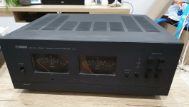
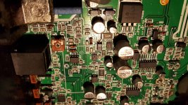
I've been slowly recapping and modding my Soundcraft 1600 console, and have some interesting measurement results I thought I'd share.

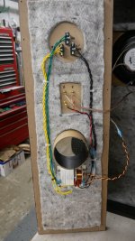
I have done all mods in sets of two channel strips, and measured the results with a MOTU 828mk3 interface using Room EQ Wizard.

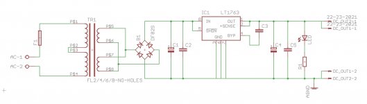
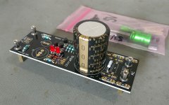
By far the biggest sound improvement was recapping the power supply. Do this first if you're recapping an old console for sure! Also I would recommend to replace any TO-3 transistor sockets, I had one that was on the way out (weak contact pressure on the pins) and might not have noticed if I hadn't specifically looked at the socket. The sound improvement was noticeably tighter bottom end throughout.

I haven't been able to hear any improvement in sound with any opamp swaps.

Mods done to channel strips are:
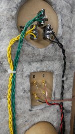
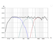
* Recapped electros with Panasonic FC (Green traces)
* Recapped with Pana FC, and also recapped film caps with WIMA FKP2 (Blue traces) Some values are not available so used other brand of non-metallized film cap for those
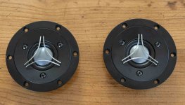
* Recapped with Pana FC, and swapped out input transistors with ZTX951 (Orange traces)

The red traces are an unmodded channel strip with original 80's components.


where can i upload my pictures online

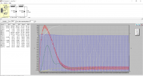
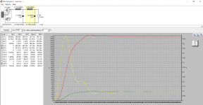
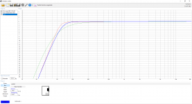
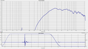
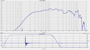
As you can see, recapping gave me back my bottom end, and everything was calibrated to within 0.1dB when making measurements.

The distortion figures are pretty interesting. Going to Panasonic FCs gave a good reduction in distortion over stock, until we get to the top end which is actually a bit worse.

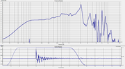
But recapping the old films to new WIMA films gave a massive improvement, which is pretty audible. It actually IS worth recapping those old film caps in this case.

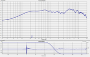
It looks like while the ZTX transistors have lower noise than the 2N4401 stock, they are a bit more distorty in this circuit.

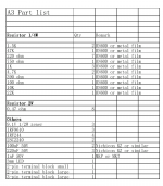
Hope this helps someone! I'll post the actual cap values I used when I get a chance; I collated several old threads from many sources and ended up with some solid recommendations that improved bottom end response, as shown above. (Edit: see post #140)

Cheers
Darren

Thoughts on this linestage?

Been looking at building a line stage and come across this design here:
https://audioxpress.com/article/High-Quality-Tube-Type-Control-Unit
Tube%20Type%20Control%20UnitFigure1[1].jpg

Any thoughts on the 5687?
It seems to have a low impedance and this is using it wired in parallel.
Could it be modified easily enough to use an EF86 as a triode? I think EF86 output impedance is around 15K which would be higher than the 5687 in parallel.
I dont have a good supply of 5687, but ive got tons of NOS EF86 and 12AX7 and was wondering if it would be possible to substitute V2A for a 12AX7, since they are similar spec tubes but not 100% identical.

Newbie power supply section help needed

Hi I am not a complete newb but by no means a seasoned hand, I've built 2 tubelab amps but want to delve into point to point wiring on my next project. I have a Decware Se84c breadboarded just to play with as the design seems simple and I have all the parts needed for it. Not sure if I'm going to build it though, right now it is just for experimentation.
Anyway my question has to do with the transformer hookup in the power section. The transformer I have on hand does not have a center tap on the 6.3v secondary as called for in the schematics ( see attachment)
What I'd like to know is can I use an artificial center tap using two resisters on the 6.3v line with this design or do I need to change something else to make it work?
The tranny has a center tap on the 300v secondary, but since it and the 6v center tap are shown tied together to ground in the schematic I wasn't sure if using resisters would be ok.

Any thoughts from you old hands with more experience building these wonderful classic tube amps would be greatly appreciated. I know answering newbie questions can be annoying at times, so I can't thank you guys enough. 😀😀😀

Attachments

2SJ109 2sk389 on ebay

I hope this kind of post is not against forum rules. I figure with how rare these are people might want to know.

I'm starting to match up some 2sk389s / 2sj109s, at some point that listing will go up.

Today I put up auctions for 10x 2sk389s and 10x 2sj109s just to see what they would go for.

http://ebay.us/1kbp0A?cmpnId=5338273189

https://www.ebay.com/itm/125281909341?mkevt

I know that people get burned by fakes all the time and to ease your mind about that I will accept returns if you are not happy with what you receive and I'll even refund your shipping costs.

A question for you guys. Are the low offset versions of these FETs particularly useful. I'm measuring them out and some have offsets less than 100uV. I'm curious if those deserve to be treated special with their own listing.

A Book of Electronics

I have decided to publish a book on Electronics, which, analyses BJT's and BJT circuits, with some JFET information too.

The book analyses this with simple logic only and without Mathematics and Physics. Where Mathematics and Physics are inevitable, the book informs the reader, so, the reader can skip this part.

A special chapter is reserved to Mathematics and Physics, used for Electricity and Electronics. The reader is informed to skip this chapter. This chapter provides readily available formulae, theorems and laws and does not derive anything mathematically.

Practically made examples are provided.

Now, the book became huge, even without the practical examples. I have double checked the book, but, I cannot carefully check everything.

The book is, also, intended to be used as a manual and help in some designs.

People on this forum are, also, not expected to read nearly a thousand pages ( and, probably, much more in new editions ). However, some may decide to choose a topic and read, say, one or a few pages.

These people are requested to, please, provide information on possible mistakes, so, these are corrected for new editions.

Here is a link to the book :

Simple, Practical Electronics - Google Drive

Aleph 3? Project.

Received some pcb's today from ebay. Aleph 3 is printed on it.
The pcb's have a goldplated copper thickness of 75um (pcb is 2mm)

My question is, is it a aleph 3? And is it any good in this form?
And, are there mods is can do directly.

Posted a picture of the pcb and the parts list and schematic that came with it.

Attachments

  • uploadfromtaptalk1420750422615.jpg
    uploadfromtaptalk1420750422615.jpg
    54.1 KB · Views: 3,348
  • uploadfromtaptalk1420750504071.jpg
    uploadfromtaptalk1420750504071.jpg
    229.8 KB · Views: 2,362
  • uploadfromtaptalk1420750523142.png
    uploadfromtaptalk1420750523142.png
    130.9 KB · Views: 2,060

Crossover Design?

So I have arrived at the Crossover design portion of a speaker... my first ground up build. I am planning to use the Z19 XO because it is highly regarded among the forum. But then I started asking why is is better than another? I have rebuilt several crossovers with upgraded parts in the past but just went off the manufacturer schematic to know how to wire it up without any study as to why. I have a basic understanding of what caps, resistors and inductors do... but not a general understanding of how they work together and how to optimize a XO for a specific speaker.

I want to understand why you would opt for the Z19 XO over a 2nd Order Butterworth XO designed to crossover at 1200hz? Why are they so many extra parts in the Z19 and significantly different cap values??? I've always been a fan of the simplest solution, but I've read enough of the Z19 forums to know that it seems to work better.

I know the answer, I need to read up. So my real question is if there is a better place than the Z10 Forums scattered across several sites to learn this information?

2nd Order Butterworth 1200 Hertz
circuit2.gif
Parts List

Capacitors
C1 = 11.72 uF
C2 = 11.72 uF
Inductors
L1 = 1.5 mH
L2 = 1.5 mH

Stock Z19 Design
1650645411313.png

Use for 2nd pair of input terminals on PA speakers?

Hi guys,

I recently bought a pair of SLS LS8695 speakers. These are passive 2-way speakers with a column of ribbons (hifreq) and a column of woofers (lowfreq) in a single box. They were originally marketed as PA speakers. I'm not familiiar with pro-gear and I had initially expected two sets of speaker bindings, one for high and one for low. Instead, I found that there are two sets of NL4 connectors.

I can't find the manual for these speakers online and I can't understand why there are two sets of NL4 as each NL4 connector is 4 pin. I would have thought that one NL4 is good enough to carry a high/low pair. Can anyone comment on what the second set of NL4 would be good for and how (not) to use them?

Thanks,

Zhao

Mosconi AS 200.4

good day bros. I am repairing a Mosconi AS 400 4 channel amp. Need help. The problem is, when ever you turn on the amp an audible popping sound comes out in all the channels. There is no popping sound during playback, only when you turn it ON ,Even with out the RCA 's input connected to the amp. The popping sound is not really loud. The amp is only 4 months old. I measured the Vdc output, it is jumping to 0.6Vdc to 0.8Vdc when pop sounds come then goes back to 0.005Vdc again. I checked all components, but i can not find any fault. Before there was no popping , only after we had used the amp in long period of time at high volume after that the problem begin to come out. What maybe the cause of this sound. can it be eliminated?

Mosconi.jpg

Mosconi2.jpg

A little enclosure design and modeling for a buddies Tahoe Video

Whipped up this design for a buddy and his Tahoe. The American bass drivers are not the smoothest but with a bit of finessing it I got a nice response curve for them. It took a little smaller enclosure than I would have liked but he has gobs of power and I went on the high side with port area and will roundover the ports so there shouldn't be any noise or chuffing.

Login to view embedded media
Enclosure Details American Bass HAWK 1244 12" 1.25 cu ft Per Sub 1 3" port 12.68 long 28.27" Port Area = 32hz Tuning Per Sub Some Math... in Cubic Inches Required Enclosure Volume = 4320 Port Displacement = 241 Sub Displacement = 678 Total Volume = 5239 28 wide, 14 length 28x14= 392 cubic inches 392/5239 = 13.3 high L 28x W 14x H 13.3

**** me, I bought the wrong box.

Hi fellas, just me trying to DIY a Dallas Rangemaster.

Fuzz Central -- Dallas Rangemaster

I've got the OC71, the problem is the box is too small and I was thinking about a separate power supply. Now, I don't know if this is a good idea or not. A regulated 9 VDC? I s this going to make it noisier and, perhaps, not as good sounding? I have very little experience with stompboxes. What do you recommend? Any schematic?

Attachments

  • DSCN1513.jpg
    DSCN1513.jpg
    176 KB · Views: 338

KEF R300 playground - measurements of raw drivers

I did some measurements of Kef R300 raw drivers. Rain prevented making full set of measurements but i found quiet enough neighbourhood so yesterday at about 01:00am some sweeps were heard from the parking lot.


https://s15.postimg.cc/5exyq4gu1/image.png


https://s15.postimg.cc/ivux8zyvd/image.png


https://s15.postimg.cc/8lsi9rgpl/image.png

This amount of quasi anechoic resolution makes it much easier to simulate the crossover between woofer and midrange.


https://s15.postimg.cc/y5cvgw7l5/image.png

I've managed to get about 9ms of gate time. I'm quite satisfied with consistency so here are files for simulators.

https://www.dropbox.com/s/dzg8gzfclgh8h92/Kef R300 sim files.zip?dl=0

Few words about it.

You'll find on axis and about 45deg off axis files in .zip folder. Only woofers are merged (between 100-200Hz). Mids and tweeters aren't because there's no need to. You have everything you need to derive Z axis offset. You'll find that frequency response of midrange+tweeter, that is needed to derive Z offset between them, drops bellow 300Hz. I am protecting the tweeter that way so, when deriving Z offset, look only how combined frequency response behaves above 300Hz in regard to reference. As far as X and Y offsets all you need to know is that woofer and midrange centers are 26cm apart. There are impedance files there. Just in case you don't like how i extracted my sim files i added HolmImpulse measurements .zip file that you can import into your HolmImpulse and set the gate to derive files as you see fit.

Here's Kef's crossover. I betcha you can do better than that if you try:


https://s15.postimg.cc/43flgo7hn/300.png

Measurements are done in factory cabinets, gated, at 1.03m distance mic at tweeter axis - gate is good to 100Hz. Holm-impulse, calibrated ECM8000, M-Audio Fast Track II USB interface, Dell Inspiron notebook.

Play and enjoy yourself 🙂

Deterioration in noise after screwing 25W 300B cathode resistors to chassis

I'm fixing 4 PSE 300B amps for someone. 2 hummed badly and all had a very poor implementation of a bus earth. 2 didn't even have a proper safety earth.

All had the 25W 300B cathode resistors mounted on strips of aluminium. They were getting very hot dissipating 5W, and one was open-circuit.

I moved the cathode resistors to the chassis but measured a deterioration in noise by ~3dB on each amp. I didn't remove the powder coating under them but thermally it's way better than before.

Before:

1650789473674.png


After:

1650789523566.png


The heaters being DC I replaced the 10-turn pots with resistors. I eliminated replacing the pots as the culprit on the 4th amp when I replaced the cathode resistors and left the pots in place and measured the same deterioration. Adjusting the pots a couple of turns either side of their centre point made no difference to the noise level anyway.

I've read that transformer core flux can flow in the chassis and introduce hum into the audio ground. The top of these chassis is 10mm thick.

But could core flux in the chassis include noise in resistors screwed to the chassis?

The amps sound great on my system and you have to move very close to the speakers to hear some combination of 50Hz, 100Hz and maybe harmonics. The owner has more sensitive speakers than I do though.

Attachments

  • IMG_9654.JPG
    IMG_9654.JPG
    241.3 KB · Views: 146
  • 300B amp power supply modified schematic.png
    300B amp power supply modified schematic.png
    14.4 KB · Views: 165
  • Modified Amp Schematic.png
    Modified Amp Schematic.png
    45.2 KB · Views: 161

Taramps Bass 8K

Taramps Bass 8K not turning on

Hi.

I'm currently working on a Taramps Bass 8000 that won't turn on.

According to the user the amp was enabled (middle terminal on the output) but the negative lead on the input wasn't properly connected. When he touched the negative input terminal with it, there were sparks and now it won't turn on.

I did some probing and inspecting without schematics and found IC9 (I think that it's a TPS7A6601QDGNRQ1) to have let its smoke out and dragging R99 (4.7 ohms, 1206) with it. I also measure a short across D6 (I think it's a SMA-packaged 1N4007) so I'll order a couple of those as well.

Currently adding parts to my cart at Mouser, and I would greatly appreciate if anyone could confirm if IC9 is in fact a TPS7A6601QDGNRQ1 (I suspect that I might be wrong and that it could actually be a TPS7A6633QDGNRQ1, or some other TI LDO). The chip's package is marked with "PA4Q".

The issue in this thread looks somewhat similar to mine: Taramps MD 5000.1 no power up and if the D21 diode proves to be shorted (haven't had the chance to measure it by itself), could anyone please inform me on what the part no. for it is? Or if it's a zener-diode, please tell me its zener-voltage? In-circuit it is currently shorted.

Big thanks to anyone that can provide me with some info on this one! :worship:

Attachments

  • 20200108_205643.jpg
    20200108_205643.jpg
    1,013 KB · Views: 622
  • 20200109_203017.jpg
    20200109_203017.jpg
    1.1 MB · Views: 676
  • 20200109_203048.jpg
    20200109_203048.jpg
    1.1 MB · Views: 588
  • 20200109_203120.jpg
    20200109_203120.jpg
    1.1 MB · Views: 559
  • 20200109_203131.jpg
    20200109_203131.jpg
    1 MB · Views: 527
  • 20200109_203216.jpg
    20200109_203216.jpg
    1.1 MB · Views: 417

Service manuals Meridian series 200

Hi everyone, can anyone tell me where to find the service manuals or schematics diagrams for the Meridian 200 series?
I refer for example to the mechanics 200, converter 203, power amps 205 or tuner 204, cd / pre 208 .... there is nothing in the world, no service manuals, nothing of nothing and Meridian has not repaired these products for many years as a result it could issue the service manuals itself ...but it is impossible.
Many thanks

500 watts enough for Ultimax 18"?

Hi,

I'm not a crazy bass head guy. Just need some low end fill and support for my main speakers. I very rarely listen above 90 dB on my main speakers for either movies or music. Debating between a sealed sub or a full marty. Sealed requires more power right? Might go full marty to get better output. Correct me if I'm misinformed.

I'm leaning heavily towards the Dayton SPA500DSP plate amp instead of the SPA1000 because it only weighs 1 or 2 KGs instead of 10 KGs and is priced quite a bit lower. Or if you suggest some other alternative amplifier which you believe is better suited.

Possible alternative to double blind testing?

Disclaimer; I have no formal education on electronics or engineering of any kind.
Had a random thought about double blind testing. Instead of relying on ears, wouldn’t it be better to use devices that are not human? Bear with me. But if you setup an amplifier and speakers, with a microphone x distance away from speakers, play a recording that we will call control A. Record the recording through the mic and call it sample A Then make changes etc and play/ record amd call that sample B. then have a program that can display the differences between sample A and B. Everything else stays the same except what ever is desired to be tested. Does that make sense or am I striking out?
Projects by fanatics, for fanatics
Get answers and advice for everyone wanting to learn the art of audio.
Join the Community
507,672
Members
7,883,521
Messages

Filter

Forum Statistics

Threads
405,994
Messages
7,883,521
Members
507,672
Latest member
rooomn