Coaxial driver advice

Hey Guys

I’m looking to build a pair of speakers for my living room. They will be mounted on the back wall. The room is 60 m2 with 5 meter ceiling height. So pretty big room🙂

I using a sub from about 100 Hz and down, and the speaker drivers will be high-passed.

The speakers will be active with a Hypex module or similar.

I’m looking for a 10” or 12” coaxial driver that will work in a sealed cabinet.

I’ve tried a couple of PA coaxial drivers and they all have this thin or shrill quality that I don’t like. I’m looking for a driver that sounds warmer than that.

I’m hoping some of you have the perfect suggestion for me. I don’t mind buying used. Maybe there’s even an old Altec or JBL coax that will work?

Hope you can help🙂

Kind regards,
Mads

A question about testing for noise

So I have recently completed my first chipamp ( https://www.diyaudio.com/community/threads/a-first-lm3886-project.386817/#post-7040805 ). To the ear it is whisper quiet but I do like to verify things and so was seeking to measure the output without any signal. I have a Levell Microvoltmeter and it serves me well.

Initially I just connected it up with nothing at all connected to the inputs and got an impressively low noise of 210muV - both channels the same.

But I thought the inputs should be shorted to get a proper measurement and so knocked up a shorting RCA plug (soldered shield to core of a very short lead - photo attached. It did have some shrink tubing on but I removed that just to make sure it really was soldered under there. Also tried with another similar lead) and used that. The measured noise goes up! I measure 1.2mV with that shorted lead attached. Of course in neither case is anything audible without sticking and ear almost in the speaker driver - but I would like to know what is going on.

I am using the 20Hz to 100kHz bandwidth setting on the Levell but all other settings are consistent (obviously noise goes down for narrower bandwidth and up for wider.

I am mystified. Is that even very short lead picking up something? Why isn't the 'something' just shorted to ground?

IMG_5469.jpeg

looking for good audio grade toggle switches

I'm looking for a line of "quality" toggle switches. These will be used for switching line level audio signals. These will be used in a microphone preamplifier for things like phantom power, phase reverse, hi/lo impedance, pad and so on. I think they all can be DPDT. I need them to have an excellent "feel" and to take some minor abuse and gold contacts would be nice. and if they could have a traditional or even retro look that is best.

I've got many switches in my parts box but none I like. I guess because I keep going for low price. This time I need "audio grade" switches. Price is still important as I might need a dozen of them for a two channel preamp.

I'm in the US, in California. so I'm looking for a US source of supply. The trouble is that there are so many. Hundreds of switches.

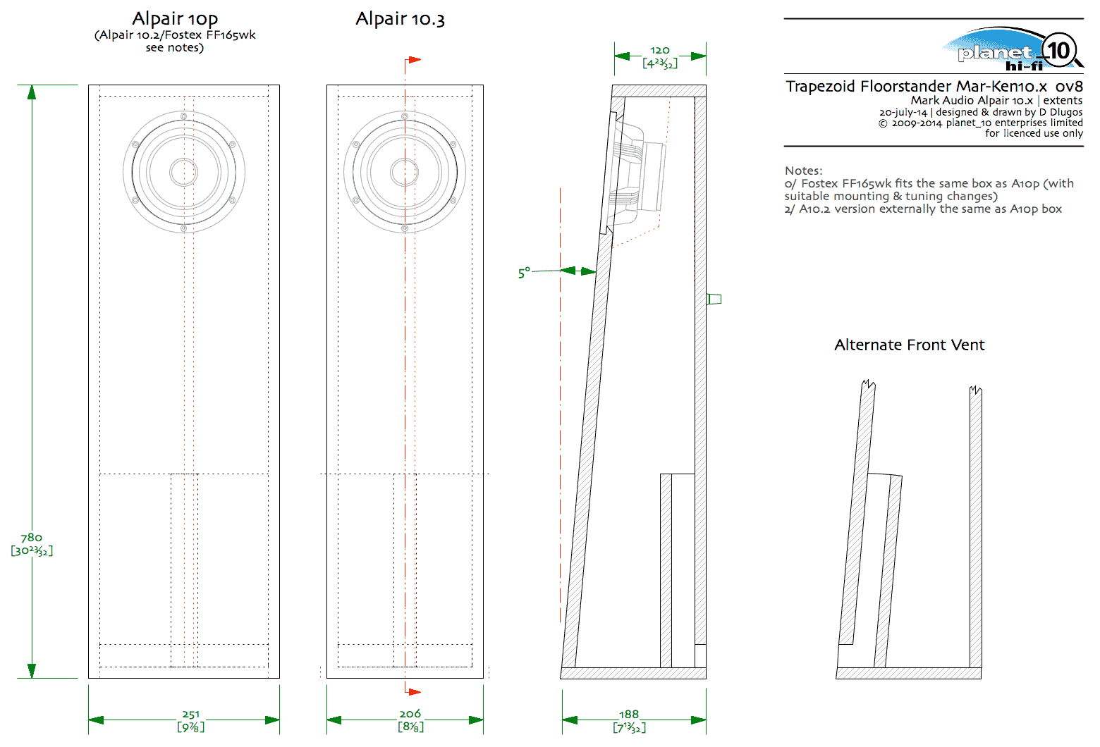
Mark Audio Alpair 10.x/FF165wk compact Floorstander Intro & Questions

We have developed a new compact floorstander for the Alpair 10p, A10.3, A10.2 and Fostex FF165wk.

As well as plans for these going into the appropriate plan-sets, we are planning on doing flat-paks of these, and want to inquire as to whether front or rear vent is preferred (designer prefers the latter)

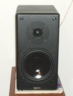
Chris has a new front row for his HT based on the A10p prototypes (with metal grills -- the Pensil 7 for comparison).

A10p-trap-FS-comp.jpg


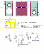
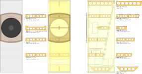
Here is an extents drawing which shows how compact these are. A10p, A10.2, FF165wk are the sameoutside demensions, the A10.3 is narrower (same as the EL70 trapezoid FS these were developed from (bottom picture)

A10x-trap-FS-extentsX.gif


The original MAr-Ken70 trapezoid Floorstander (the small speaker in front, in solid yellow cedar by Bernie)

MK70-trap-FS3-comp.jpg


dave

FS: A lot of PCB's

Here we go...
Hiraga 2 PCB's 5 euro each
JLH 2 PCB's 5 euro each
Lynx V3 8 PCB's 7,5 euro each
F4 4 PCB's 7,5 euro each
Aleph30 4PCB's 10 euro each
AlephJ 12PCB's 10 euro each
Aleph mini 2 PCB's 5 euro each
Hawk A18 2 PCB's 13,5 euro each
MC phono (Peter Daniels design) 1 PCB + SMD opamps + Xformer - make me an offer.

Also have 4 PCB sets (Driver board, 2 output boards, 1 powersupply board. These will build a Pass X=amp with 20 fets per channel
Pls PM for more details. PCB's are designed for output currents of 50Amps.

P.S. for the Pass lovers....Have a lot of selected fets laying around that are VERY closely matched.

Carver Magnetic Field Power Amp -whazzit????

I don't know 'what' this gizmo is so I put it here. Can anyone explain what a Bob Carver Magnetic Firled Power Amplifier is? I have wondered about this for long enough. There is a pair on ebay now here. < http://cgi.ebay.com/Pair-Bob-Carver...839295670QQcategoryZ71544QQrdZ1QQcmdZViewItem >

With a name like that I have visions of a saturable reactor being used as the amplifying device. Am I correct?
  • Like
Reactions: Cataudio45

Better bass? How and why?

I've had two prominent speaker designers tell me bass can only get so good. The Bordeaux loudspeakers for example, has its designer stating he doesn't know how to get better Bass then the Dayton audio reference series can give him according to the Distortion measurements ge gets.
Another designer says never spend mire than the cost if LRoy woofers ... because your SQ will not improve.
Are there bass drivers that actually sound better, IF the distortion is already super low?
Thanks for the education!

Kenwood KR-6600 amp board advice

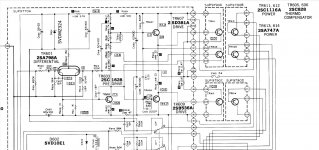
Hello all, newbie here who created their own issue - shorted the wrong pins when connecting meter to set bias. When I did this a pop happened and all the sudden the 180ohm R58 resistor went glowing red. I have 180 ohm resistors to replace this one, however I’m wondering if this is a protection type resistor that stopped further damage. The four main transistors on the power amp board all seem to check out fine and do not seem to be shorted. I see no other evidence (visually) of any other burnt up resistors, just this one.
any advice you can give I would greatly appreciate it. I’m including a pic of the board showing that resistor and a copy of the service manual if needed.
This will be powered back up with dim bulb tester in line next time as well

Attachments

How to Fabricate Amp Cage?

Hi all,,, I have this great little Bogen amp chassis that needs a cage cover, about 4" high, 7" deep & 11" long. I saw the perfect metal at Home Depot, but don't know how to quite pull it off. I tried looking for YT tutorials, but all you find is Farady & bird cages. Please check my photos for 2 different cage styles on my exact amp. I'm sure I wouldn't need a degree in Origami, but any tips? I'm not looking to do the exact replacement, just a rectangular cover that would be open air on all 5 sides.
Thanks all & stay well!!

Attachments

  • Screenshot_20200821-194729_Reverb.jpg
    Screenshot_20200821-194729_Reverb.jpg
    203.7 KB · Views: 458
  • Screenshot_20200821-194648_Reverb.jpg
    Screenshot_20200821-194648_Reverb.jpg
    465.7 KB · Views: 472
  • 20200821_194236.jpg
    20200821_194236.jpg
    846.9 KB · Views: 483
  • 20200821_194216.jpg
    20200821_194216.jpg
    771.3 KB · Views: 492
  • Like
Reactions: Coldhead

Sony CDP-30 Won't Read TOC - Diagnosis Thread

Looking for expert attention. I will add photos and hard info later.

CDP-30 from thrift store. The manual says KSS-121A but really it's KSS-120C. RF Amp is CX20109, Focus/Tracking/Sled is CX20108, DSP/CLV is CX23035.

Clean, powers up, display bright, laser lights up, seeks and locks focus, spins, locks tracking, but does not lock spindle, and gives up again.

In Test Mode (uC pin 22 grounded), it keeps spinning but still does not lock. Speed goes up and down, never stopping or winding up super fast. MIRR is low (false) with bursts of high. GFS is low (false) with occasional pips.

Objective lens tracks for some seconds then jumps and resumes tracking, so sled is not moving. This may be uC intentional because I know the sled can move - if I mess up E-F balance far enough, the sled wobbles outward or inward on its own.

Initially RF was absent, but I think the sled was hard against the stop due to dirty contacts on the limit switch. With exercise, limit started to close and now when I crank the sled outward by hand then unload/load, it cranks in and stops when limit closes, and we get some RF, presumably the TOC.

RF is weak and (of course) blurry, with dropouts that IIRC are not once per rev but some slower pace, not necessarily regular.

Here's a clue, I think. If I unlock tracking (by grounding TE at RV104 slider), RF increases. A lot. (That is, the maximum increases; minimum is zero as we drift off the pit spiral on every revolution.) Maximum amplitude is a volt-something for sure. When I allow tracking to lock again, RF goes weak again.

What do you think, grating's come loose? (Plus the failure to lock spindle, which might be a separate problem.)

Thanks,
Dave

6 Channel Amplifier for LXMini+2

Hello,

I recently got LXMini+2 and really like the sound. It offers big spacious sound that is hard to get from boxed speakers.

I would like to ask other LXMini+2 owners what amplifiers use and recommend. I am currently using a cheapo 6 channel class D amp from PartsExpress and would like to upgrade within a reasonable budget.
https://www.parts-express.com/Sure-AA-AB34181-6x100W-TDA7498-Class-D-Amplifier-Board-320-307

I found that most of the multichannel amps are AV receivers when I google 6 channel amplifiers.

If you are using LXMini+2, may I know what amp you are powering them with? I see that Emotiva power amp is common choice and wondering if there are better ones out there without spending a lot of money.

I am also okay with DIY route too if it is not too hard to make them.

Thank you very much for your suggestion in advance. 🙂

DSP options?

I can't as yet build the needed new subwoofers due to the budget restraints related to Covid.
Pulled the old passive boxes from the shed and they need some help to boost the bottom end. I was going to buy a new XO unit and use the parametric EQ of the Behringer Ultradrive DCX2496LE [ replacing the current CX 3400] but there is a cheaper option in the Dayton DSP unit.

Just a quick and dirty solution to get some bass boost down low

These are the CerwinVega Vega124s in large sealed boxes; which can take more power than I currently have available, and the pair is also the stands for the tops
Funds are tight and if the cheap unit would work I'll go with what I can afford

DSP for a DIY version of Genelec W371A. Possible?

I've been toying with this idea for awhile, to build subwoofers like the Genelec W371A. I've read about DSP for multiple subwoofers for years, so I feel this is a clever application of those ideas. But I'm not sure if there is an off the shelf DSP that can do the job? A MiniDSP 4x10 would have enough channels. The mains would have to be on the same DSP

For background, what Genelec is doing is combining a front firing 14" woofer and a rear firing 12" subwoofer in the same cabinet. The frequency range of the 2 drivers overlap, and the different placement of the 2 drivers is enough to create different room nodes. The EQ takes advantage of the different room nodes from each driver and adjusts both drivers individually so together they create a flat response.

I already did some rudimentary testing of this concept. I have 2 M-Audio BX subwoofers, and I stacked them on top of each other, with the bottom speaker facing the rear and the top facing the front. The height of the two subs stacked was 34". I also added spacers to get 41", and again raised it to match the Genelec's 43" height. This test is NOT meant to represent what Genelec's product does, but it is intended to see how much of an effect this unique speaker alignment makes.

I found that the 34" height showed the most difference in room nodes, in my very not good room. (The subs were spaced ~32" from the wall.) The effect seemed to diminish with height, but I expect it begins increasing again at a certain height.

I also found that it works for a limited frequency range, between 60hz and 200hz. The response curve above and below were identical in all tests.

This leads me to believe that Genelec have a trick they do not mention in their marketing--they sum the low frequencies below ~60hz and below! The driver separation on the individual w371 is not enough, so the low frequencies are split between the two W371 units, using the same DSP trick.

I think this last trick is the one that is hardest to pull off for an off the shelf DSP? Is it possible to low cut two stereo channels at 60hz, sum everything below 60hz, and combine that summed signal back into the original stereo signals?

Measurements via FuzzMeasure:

34" stack

34 subwoofer stack.jpg


41" stack

41 subwoofer stack.jpg


43" stack

43 subwoofer stack.jpg

Weather Change and Bias

I built and initially biased my F5 going into summer last year. Lately with the onset of winter the ambiant temperature has dropped down into single figures. Yesterday I fired up the F5 when I noticed it sounded a little thin. I checked the bias and noticed it had dropped down from 0.59 to about 0.56v, DC offsets had gone up to around 10mV.

Is this normal when ambient temps change this much?

When I built and biased the amp, ambient temps where about 25degC., they're now down around 8 degC. I checked the thermistors, they've not moved. Bias voltage are stable so I figure the thermistors are good, its just the bias dropped as outlined.

Audax pr170mo Woofer selection... which 15 inch woofer 98db eff...

hi everyone

I already have my Audax pr170mo and audax pr120 in a 30L sealed box and Im looking for a hi-efficiency woofer, around 98db eff that can reach down to f3: 35hz. im willing to use a very big bass enclosure (up to 250L) if needed.

ill use a 400hz 1st order XO

my choice so far for hi-efficiency 15 inch woofer are:

Eminence omega pro15
Beyma 15b100
Audax PR330M0
JBL 2226h

Id like more recommendations and suggestions!

my budget is max 600$ for the pair.


thanks a lot

Cabinet volume question / woofers

Ok this might be a dumb question but here goes.

when constructing a cabinet and using two woofers do you follow the recommendations from the woofer specs which for example might say 30 liters?
So for using two woofers you would have to use at least a cabinet with 60 liters of volume ?

is it also dependent on the crossover?
what cabinet size would be needed for let’s say a
2nd order
3rd order
4th order?

much appreciated !

Removing SMD components; masking

I am preparing to remove a pair of smd clocks, and was going to flood them with solder and remove them. The potential issue is that there are some very small capacitors nearby that would be best left if possible.

Has anyone successfully used a masking scheme to prevent any solder from disturbing nearby parts?

Painters tape would even work, any residue removed using a mild solvent, or alcohol.

Magnetic feet

I am not sure if this has been discussed yet. The search function did not give any hit.
Let's take two neodymium disc magnets with their same magnetic pole facing to each other, so there is a repelling force between them. The closer they are the bigger is the force. Put the magnets in a somewhat larger diameter PVC or copper tube, and support from both ends with some cylindrical rods.
This construction could act as a spring, used as feet of a turntable, amplifier, loudspeaker etc. If more weight should be supported, more magnets could be added.
Has anybody tried it?

Single-crystal OCC Wire - Can It Make a Difference?

I recently posted up a request for good sources of OCC wire to make some nice DIY cables of all sorts. I'm still waiting on the materials to make the cables, but I was wondering what the community here thinks about the possibility of higher-purity single-crystal wire having better signal transmission properties than the same gauge of wire made up of many grains?

Here's the theory as I understand it (copied and pasted from my forum posting asking for sources of OCC wire):

Everything made of atoms has a structure to it. In metals, this structure is crystalline below specific temperatures (when they are solid), which occurs at a different temperature for each metal. Take a look at some of these microstructures of the crystals that make up metals:

crystalgrain1.jpg
crystalgrain2.jpg
crystalgrain3.jpg


And wherever the crystal structures (or "grains") meet within the material, you have microscopic "grain boundaries," like this:


CrystalGrainBoundary.jpg


When electricity travels through material, it has an easier time (less resistance) flowing across fewer grain boundaries. Electricity obviously jumps gaps, either at the atomic level, or at the macro level like how electric current can literally jump across the air from a door handle to your fingertips when you have enough of an charge-differential between yourself and the door handle, say after your feet have exchanged enough electrons with a wool rug.

Check out this primer on the flow of electrons to create electric current >>

The organization of the crystalline structure of a metal wire is dependent upon the purity of the material used, and more importantly the manufacturing process of the wire itself. By using casting techniques at controlled temperatures, it is possible to create metal materials which are organized as one continuous crystal structure as opposed to a fractured assembly of crystal structures, with far fewer grain boundaries. One guy who did this is Dr. Ohno (queue that awful TikTok song) who patented the "Ohno Continuous Casting" process (OCC).

Here are microphotographs of the crystal structure in OFC (oxygen free copper) vs OCC copper for illustration:

occ.jpg


So far these are well-settled scientific facts, not audio theory.

The theory is that by allowing the modulating voltage of the signal to move more continuously along a single crystal structure, unimpeded by the normal breakages you'd find in the many-crystal formation of the regular metal material, you will get a smoother signal.

I have heard the argument that resistance is resistance, and that's how wire should be measured. That feels a bit like comparing 90 mph in a Ford Taurus vs 90 mph in a Porsche 911. The speed gun shows 90 mph on either one, right? But your experience of traveling that same speed in a vehicle designed for high speed will result in a smoother ride. The comparison here refers to the musicality of a cable. Maybe resistance isn't just resistance, and maybe there are other factors involved which do affect the end result that reaches our ears, which we are more sensitive to, and which don't have discrete measurements.

It would be cool if everyone could stay respectful in this, sticking to your own opinion without judging others' opinions. I'm just wondering what everyone's take is on this.

So...can a single continuous crystal structure of metal material help audio signal transmission? Would single-crystal metal make no difference whatsoever? What do you think?
Purchase of usb I2S converter

I would need a recommendation for USB to I2S converter. I need the best possible sound quality. There are too many producers and sellers and it is not easy to find your way around. Is there any sound difference between xmos XU208 and XU216?

I like jl-sounds for its wide range of settings and options external masterclock, xmos from diyinhk has compared to that a more powerful XMOS chip. I don't need a flip flop reclock or isolated i2s. Diyinhk do not offer any datasheet for their product. It is not good to buy only according to the picture, even if iz has more powerful xmos. Masterclock from diyinhk is only 49,xxMhz? I have older DAC, i need also 24,xx MHz MCLK.

Thank you.

I2SoverUSB - I2S over USB Audio
Home
XMOS 768kHz DXD DSD512(DSD1024) high-quality USB Type-C to I2S/DSD PCB - DIYINHK

Coaxial drivers for ultimate speaker?

I have come a long way building loudspeakers, first with traditional passive crossovers and then switched to most advanced custom digital crossovers using Analog Sharc DSP processors. Also I have always used upper market drivers like higher Scan Speak or Seas lines. Based on this experience and experimenting with different designs and DSP I believe the best concept to build an ultimate quality loudspeaker is using a coaxial driver or possibly a fullrange plus tweeter. The key justification is our ears are much more sensitive to timing dimension than to the frequency reponse. This is getting more and more recognition recently in hi-fi, see e.g. MQA technology.
Coaxials or fullrange are much better suited to time dimension fidelity but a question I am not sure about is are there drivers on the market that offer comparable overall speaker parameter quality as the best classical drivers ? Or is it more a niche segment where no serious R&D is happening ?
I am not interested in opinions how coaxials/fullranges "sound" since it is way too much dependent on the individual appplication and conditions. It is more about their technical parameters, technology advancement and overall technical potential. I am not too much worried about problems in frequency response either since I can correct them using DSP . Although unfortunately any DSP also distorts the timing since otherwise it could not work. So what I need is decent FR and best possible impulse response in possibly 150Hz - 15kHz range delivered from a point source over this range.
The ones that I have looked so far were Seas Prestige coaxials and Jordan Eikona fullrange.
What are your opinions or experiences with coaxials/fullranges ?

Magnus 1400 "Cathedral" chord organ - any info?

I just picked this up for next to nothing on FB Marketplace. Very cool piece!

I can't find any reference to this model anywhere, nor any pictures. It appears to be the "mack daddy" of the Magnus Electric Chord Organ line - it has every feature that I've ever seen on a Magnus; 37 key manual with switchable chorus, major and minor chord box, 8 bass tabs, voicing switches, tremolo, and a surprisingly beefy tube amp (push-pull EL84, with three 12AX7 for preamp, tremolo oscillator, and phase inverter, EZ81 rectifier) going into a comically-undersized 8" ceramic speaker. The transformers date to late 1961, so it's probably a 1962 model.

The acoustic portion works perfectly - quiet blower, no hung notes, no sticky keys, all chords and bass notes work. The amp needs some work, but hopefully it's something simple; the rectifier lights up, but none of the other heaters come on, so I suspect loose/broken heater wiring. Regardless, barring a blown transformer, I'm sure I can fix it.

Unfortunately the manual is about 20 cents sharp, and the bass tabs are a full quarter-tone sharp, but that's what Melodyne is for, right?

I'll add pictures later when I get a chance. In the meantime, is anyone else familiar with this model, or can anyone provide any other context? Thanks!

Is Room Correction Always Really Necessary?

There seems to be a certain train of thought in this forum that room correction is always necessary. That every room must have some sort of absorbers or reflectors in order to get the best sound possible for you to enjoy. And there are no exceptions or differences as a function of the type of music you listen to. At least that’s the impression that you get when reading a lot of the posts here.

But is that really true? Well some experts certainly don’t think so. Take for example Toole where in his book on page 197 he says:

…”we decided that absorbing side wall reflections seemed to flatter some recordings (mostly pop/rock) while leaving the walls reflective flattered others (mostly classical and jazz).
Conclusion: one size does not fill all. Personal taste, music and the reason for listening are all significant variables.”

But here we see many people who insist on room correction as a must regardless of the type of music being played or any other variables.

It seems to me that the need for room correction, if any, is a lot more complicated and is based on many more individual details than often presented here.

Current Sharing in parallel diodes

I was thinking about current sharing in parallel damper diodes (or diode wired triodes for that matter). Not being able to find a rule of thumb I decided to crank up LTspice and see what I could see as it were.

To simulate fairly mismatched diodes I used two somewhat similar triodes in the form of 12AU7 and 6SN7. As a first pass I ran a single 12AU7 and divided current by voltage drop and got an effective resistance of 2K. This is no where near the data sheet Rp but I just ran with it. Now with the two "diodes" in parallel with a 2K resistor in each plate I got a 10% current difference v.s. 32% with none (1 ohm) and 27% with 200 ohm resistors.

I suppose the 200 ohm would be "safe" but the 2K seems really solid given that the simulation was with totally different triodes.

Does anyone have a rule of thumb that they use?

CurrecntShare.png

YBA CD3 with Sanyo SF-P1 lens tracking problem : Please help.

Hi,

The player is unable to read TOC and play cd discs frequently.

The lens is cleaned.

Attached photos of the player showing tuning ports that can be adjusted to make the player track properly again. They are F OFFSET, F GAIN, E/F BAL, T OFFSET, T GAIN, K GAIN, PLL F.

An externally hosted image should be here but it was not working when we last tested it.


F GAIN, F OFFSET, E/F BAL was tuned ( rotated anti-clockwise ) years back by the authorised agent when the player had the same issue.

If you have knowledge with Sanyo SF-P1 lens / circuitry / tuning, give your advice.

I have ordered a New identical original SF-P1 lens to replace. Should i set all the tuning ports to original factory makings after changing the lens?

An externally hosted image should be here but it was not working when we last tested it.


Regards.

Placement of resistors in signal path.

Good evening, I just wonder. Maybe this is a silly question but here we go. Say we have a construction that have a resistor in signal path, then a another component then a resistor again. Or even 3 resistors in the signal path. But say we have two. And you have picked up two resistors that you will go for, say Shinkoh Tantalum and Vishay VAR / Charcroft Z-foil The first one natural and tiny warm / colored and the second one neutral with no coloration. Witch to place first in line, the one that has the clean sound or the one that set the " coloration / warmth ? Or does it not matter? Or why mix two different brands, just go for one brand ? ( I know I with many like to mix parts to maybe get the good stuff from both parts ).

Frank

Texas Instruments LM4700 chip amp

Why isnt there any information on the Texas Instruments site about their Overture high chip amplifier LM4700 ?

Search results - TI.com

4700 suggest its "the newer and follow up version of" 3886, yet it has become obsolete. Why?

Also how does this LM4700 compare to the LM3886 in terms of high fidelity audio quality?

Is TI's LM3886 after all those years still their "highest fidelity" chip amp in the critical 1W ~ 10W range?

Visaton-Monacor 2 way sealed simple loudspeaker build plans

Hi,

Considering how troubled times that we live in are now, I figured someone might want to build a 2 way loudspeaker on a budget of reasonable sound quality that I have done once for a friend of mine. I haven't got access to any measurements right now but I am confident everything is okay with it. It is a sealed cabinet, so it is supposed to be stuffed with polyfiber wadding to a reasonable extent. It was voiced by measurements and listening.

As far as I can remember, general specs would be something like:

Sensitivity: 84dB/2,83V/1m
Impedance: nominally 4 ohm (lower mids); 6 ohm (mid to hf)
Range: 60Hz(-3dB) to 20kHz(0db)

Attachments

  • Visaton-Monacor 2 way project.png
    Visaton-Monacor 2 way project.png
    215.1 KB · Views: 6,611
  • Finished.jpg
    Finished.jpg
    28.8 KB · Views: 7,460
  • BOM.txt
    BOM.txt
    857 bytes · Views: 462

JWCO aluminum electrolytic capacitor annual output of more than 20 billion sell well over the world

Yongji Economic and Technological Development Zone and JWCO group held "electrolytic foil project investment cooperation agreement" signing ceremony, a total investment of 600 million yuan of high-performance electronic energy storage materials production project officially settled in our city. Mayor Huang Yaping attended the signing ceremony and met with JWCO Group Chairman Zhang Liwei and his delegation. Municipal Standing Committee, vice Mayor Li Xiaojun presided over the signing ceremony.


Yongji Economic and Technological Development Zone management Committee vice director Chen Jin on behalf of the development zone and JWCO Group chairman Zhang Liwei signed the "electrolytic foil project investment cooperation Agreement". The production project of high-performance electronic energy storage materials spans the two industries of aluminum deep processing and motor manufacturing. The total investment of the project is 600 million yuan, and the investment of the first phase is 300 million yuan, and 30 electrode foil forming lines and living facilities are built. The annual output of foil forming is 10 million square meters.


JWCO group is a manufacturer of high-quality aluminum electrolytic capacitors integrating professional research and development, manufacturing and sales. Currently, it owns 8 companies in Guangdong, Jiangxi and Jiangsu, with an annual output of more than 20 billion capacitors, which are sold well all over the world.


Contact us:

RFQ:quotes@huanyupcb.com
huanyupcb@126.com
WeChat:+86 15915902291

A first LM3886 Project

Well what a great forum this is. I have learned a lot from browsing on here and decided to implement a first project - an LM3886 amp. Boards were acquired already populated and are marked BrianGT. Chips are all verified genuine from legitimate suppliers. I read the "Done Right" material and tweaked a little by adding the Theile components. Since the photo I have also added RF filtering to the inputs.

The amp is built into a Cambridge Audio A3 (V3.0) case and uses the original transformer and mains switching. This case is Class 2 (rated double insulated and so the transformer must be compliant). and so there was no PE. Since I haven't altered the mains wiring arrangements and have only modified to add more insulation I have kept it that way. OK there is one error as is -- the IEC socket I added is 3 pin as I am awaiting the arrival of the rarer 2 pin variant.

The "preamp" is an Alps 20k pot - nothing added. The strange white things on input are actually the DC blocking caps in shrink tube.

All worked first time. I did a few rudimentary checks before switching on. DC offset was minimal (in spite of the boards omitting Ci), noise (measured on a Levell microvoltmeter) was truly minimal, and it reproduced sine and square waves as well or better than my NAD C320 (I only have a low spec Picoscope so this is very subjective really - eyeballing the traces).

Anyway ... great fun.

IMG_5414 (1).jpeg
  • Like
Reactions: borninthefifties

Gainclone...No gain, YES pain.

I tried gainclone with gain=1, and it got pretty hot in a very short time. I think, according to the others' comment in this thread, it is due to an oscillation. I tried both T and TF package, and both of them got hot. Actually, I was thinking to use a gainclone as a power amp without any gain, but it doesn't seem to be possible because of the nasty oscillation.
What I'm thinking right now is that if I set the gain of gainclone to, say, 20 and put a voltage divider at the input before the coupling cap, and hook it up to a tube preamp with a maximum gain of 20 dB, would it be worth trying? As I heard, the main benifit of using tube amps is at the voltage amplification. In the configuration stated above, voltage amplification is done first at the tube stage, and signal gets lower by the voltage divider, and then voltage is amplified again by gainclone. In such a case, there wouldn't be any benifit of using a tube line stage, IMO.
I would like to know what others think about this configuration. Is it gonna be worth trying or a waste of time and money?
Thanks in advance.

Old American Beauty 100W soldering iron or new iron for chassis work?

I have a pretty old 100W American Beauty soldering iron I inherited from my late grandfather, and at some point, I got a new 43D diamond shape solder tip for it and generally cleaned it up, the idea being to use it for soldering chassis connections like ground connections on some Fender amps that a regular soldering station can't handle. The thing is, it's not working as well as I'd hoped, and I'm wondering if I really need a 43C chisel tip for better heat transfer or if I should just buy something like a Weller 175W iron for these tasks.

One observation: The solder tip does not fit snugly in the barrel of the iron, and since I only have this one iron, I don't know if anything is missing, like a sleeve that should be inside the barrel. (I don't have one in known-good condition to compare it to.) Rust had roughened the inside of the barrel, but I removed the rust with Noxon 7 polish a few years ago. Still, I wonder if I'm getting optimal heat transfer to the tip. Is the tip supposed to fit snugly in the barrel?

I can tell that the heating element is drawing 100W, so that's not in doubt. I'm just not sure it's getting where it needs to go.

Or is a 175W iron really needed to do these jobs properly?

STK7100 for Vintage Amply Yamaha R1000

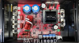
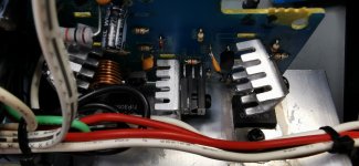
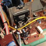
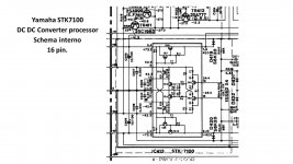
Hi, while restoring radio amply Yamaha R1000, I have found a problem in to DC DC Voltage converter Processor named "Yamaha stk7100". This device has 16pins and coverts from +/- 73VDC and 42,5VDC to +/- 42VDC and 24 VDC and 25 VDC in each specific pin. But it does not provide the valid voltage to the main amply stage, it should convert form +/-73VDC to +/-42 VDC but it works only for one branch/side respect to the zero, the other is left to 73VDC (-42VDC ; 0VDC ; +73VDC). Somewhere I have found that maybe Darlington STK 3106 (Maybe Sanyo) may be the corresponding/equivalent one for commercial brand.
Has anyone faced the same problem? Does it be possible to find a conversion table from this probably proprietary label from Yamaha to a commercial one, e.g. Sanyo or others? Thank you very much for each useful comment or reply and sorry for my terrible English and not being so experienced in electronics restoring.

Attachments

  • yamaha r1000 stk 7100 processor small.jpg
    yamaha r1000 stk 7100 processor small.jpg
    99 KB · Views: 199
  • hfe_yamaha_r-1000_schematic.pdf
    hfe_yamaha_r-1000_schematic.pdf
    5.7 MB · Views: 160
  • STK 7100 Yamaha.jpg
    STK 7100 Yamaha.jpg
    126.8 KB · Views: 199

Effect of Enclosure Volume in Ported Loudspeakers

Designing an IB enclosure appears to be relatively easy: find an enclosure calculator, enter the T&S parameters, choose the desired Qtc, press go and, Bob’s your uncle, you’re done!

From what I gather, designing a ported speaker (as a first approximation) appears to follow a similar approach. However, in all the calculators and design explanations I’ve seen, the initial enclosure volume calculation is never discussed, yet I’ve seen it stated that at frequencies above the port tuning frequency the enclosure acts as an IB. If this is the case, then surely the enclosure volume would influence the the slope of the frequency response between (say) 200 Hz and the port tuning frequency?

Angel Hair Speaker Wool Manufacturer

On another forum, the Mundorf Angel Hair, used a wool in a speaker enclosure was receiving a good appraisal from a few users.
I followed up on a bit of additional supplied info, and the following is what I discovered.
It might be of use to somebody, as a material to be considered on a project.

If one does their homework, they should be able to satisfy themselves about this material as a usable product.
_______________________________________________________________________________________________________________-

The Link is to the Dutch Manufacturer.
On their products list, Teijinconex is the only Fiber Material I could find.
If the Angel Hair is this Material, as I assume it is, as I also found a reference to Twaron Angel Hair. then this link will show the full intended purpose of the material, as proposed by the producer.
One thing for sure is it is a material with a intended purpose for State of the Art designs.

https://www.teijinaramid.com/en/product ... ple-fiber/

Tapered TL for DIYSG Vortex-15 (Denovo Hyperlite CX15-8)

This summer I ordered some of the clearance Vortex-15's from DIYSG. As a design exercise I worked up both a tapered TL and MLTL enclosure design using Hornresp.

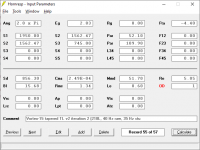
Here is the hornresp input for the tapered TL. This was done using the t/s specs from here.
Vortex-15 Tapered TL v2i2 input.png
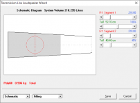
Stuffing modelled is ~2 lbs of polyfill over first 40" of the line.
Vortex-15 Tapered TL v2i2 stuffing.png
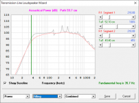
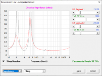
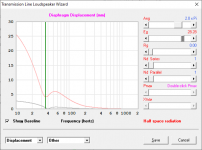
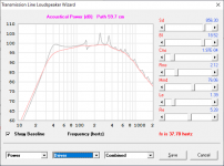
Power response and impedance. Tuning is 39.5 Hz before stuffing, 35.7 Hz after.
Vortex-15 Tapered TL v2i2 power resp.pngVortex-15 Tapered TL v2i2 impedance.png
Displacement is just a hair over xmax at 100w input.
Vortex-15 Tapered TL v2i2 100w disp.png

Model tested with driver measurements posted by Brinkman in this thread. The raw response is a bit lumpier, but with stuffing it turns out nearly the same.
Vortex-15 Tapered TL v2i2 power resp (Brinkman driver meas).png

With things looking reasonably good here, I worked up a cabinet. Keeping the original design's 17" width, the dual requirements of reasonable tweeter height and box depth resulted in more wasted space than I would have preferred, but I couldn't think of another way to do it. Obviously this is a very large speaker - exterior is 17"w x 21"d x 55 1/4"h (not including the cosmetic double-baffle)
Vortex-15 Tapered TL v2i2 cab & bracing v1.png

The MLTL has a similar floor footprint but is less imposing at 44" tall and with a slightly lower stuffed tuning of 30 Hz. I can share that one too if it's of interest to folks. I'm still not sure which I'm going to build, and I've not listed to either an MLTL or TL design before.

Are B&W Bass Drivers Interchangable?

Hi,

I have a B&W Nautilus HTM1 centre speaker and one of the bass drivers has failed. These drivers don’t seem to be available anymore so I was wondering if a bass driver from a Nautilus 804 could be substituted? I understand that it might not be an optimal solution, but it would be better than having only one driver operational.

The Nautilus HTM1 part number is ZZ10693.

The Nautilus 804 part number is ZZ11304.

The drivers look the same from the front and I believe the HTM1 was designed to compliment the 804s.

I’ve been asking this question directly to B&W for 2 months but all they will tell me is that the speakers have a different part number.

Thanks 🙂

Audio App for iOS or Android with Time Alignment

Hello everybody,

I'm searching for an smartphone app where you can set a time alignment function for one channel.

Like in the Windows-App EqualizerAPO where you can simply setup a config file with "Channel L Delay = 1,5ms"
and then everything produces an audio output will be delayed for 1,5ms on the left channel.

It is important that the manipulated output will be directed via bluetooth.

Thanks a lot.

Greetings,
Robert

the speed of light and the 1/4wave speaker

this is WEIRD👽👽👽???? especially if you look into it further...

when 80/2.54 is 'pi'...3.14960(62992)125984(251968(503936)007872(015744)31488(62988)129..
22/7 is 'pi'...3.142857(142857)(142857...
and obviously pi is 'pi'...3.1415926..

2.75/7 is .39285714(also39.37) and 2.75/2.54 is 1.082677165(35)4339070)866(14)1732(28)3464(56)6929(112)133858(224)267716(448)535433...
(24)...
5.5/2.54 2165(35)433(070)866(14)1732...
11/2.54 4.33(070)866(14)1732...
22/2.54 8.66(14)1732...
(this gets interesting!)? each as (/7 and 2.54 in a calculator with a big screen( out to long decimals)
5.5/7 .7874(216... 2.165(35)433(070)866(14)1732(28...
11/7 1.5748(432)1728 4.33(070)866(14)1732(28(3464(56)...
22/7 3.1496(864)3456 8.66(14)1732(28...
44/7 6.2992(1728)6912
88/7 12.5984(3456)13824
176/7 25.1968(6912)27648
352/7 50.3936(13824)55296
704/7 100.7872(27648)110592
1408/7 201.5744(55296)221184
2816/7 403.1488(110592)442368
5632/7 806.2976(2201184)884636
11264/7 1612.5968(4402368)177272

1/2.54 is .3937 is inch to meter (22.5 and 1/8pi) (pendulum swing of 30degrees at that length is 1 second @30degrees(pi/6) or 12 on 6.9375.
1.609344 is km to mile (92160 and 512pi)

when pi is 80/2.54, then, when the speed of sound is 360x (pi) = 1133.858267716535 (345.6)then 1 meter is 86.4 (the diameter of the sun x1000)and 24 hours of seconds and Jupiter's diam(x100 as well as Saturn's orbital mean in milesx100000000

so then what?

864x 1.609344 is 1390473216(suns diameter in KM... Saturn's orbit at perigee, Jupiter in km, (just over 16 days in seconds(13824) (1690344 x 3937 is 666xxx mph (light speed) and (432)^2 is 186624 mpsec(close) and (1728) ^2 is speed of light msec(close).

360 cm subwoofer (first) one , under desk, , one huge(for fun)

but what does this all mean? or how is it connected????

why does it perfectly cancel out (432hz), 864.0, 1728, 2592, 3456, 4320, 5184 (the exterior hypotenuse angle of the great pyramid corners), 6048, 6912, 7776, 8640,9504, 10368, 11232, 12096, 12960, 13824, 14620, 155..16.17280, 18,19, 20, 21600, .. at -990dB i simulation? when split up "perfectly"...

1609.142857 is 512 pi
392857 is 0.125 pi

pi/9 is the exact location for driver entry in all TLs (0.349206349) to precisely fill the 3x (1/4 Fb) void in response. that is also (432)^4, which is (186624)^2.. (speed of light in miles psec.

There's so much more.. the Pythagorean theorem to 1728/864 to yield 149.6 hz(the first peak in the response of the compoundTL at 360 cm

Attachments

  • Like
Reactions: head_unit

Custom Console for Controllers: SSL UF8 + UC1 + Presonus io24C FaderPort

I am planning to build a custom table-top console to house SSL FU8, SSL UC1 and a Presonus io24C FaderPort. In front an Apple Magic Thin-line Keyboard and Trackball will sit. Thinking about locating a 24" to 32" Wide-View Monitor dedicated for FU8 & UC1 related mix screens. 19" rack space Left and Right for ADA Interfaces, Series 500 modules and patchbays.

Suggested links and ideas please.

coupling caps 3 approaches

This post is to present a 3 design alternatives to the coupling cap approach that I would like to share.

The traditional coupling cap is a single cap based on frequency response and DC offset. For high voltages this means physically large caps. I call this One Big Cap in the attached PDF.

A couple years ago I move to 2 smaller caps in parallel which increased speed, reduced cost and somewhat reduced the space needed. This is the two in parallel approach.

Lately I have been using WIMA SMD films. Small in size but also small values. So while this ticks off the space and speed boxes. There still can be some leakage. Stacking the caps help reduced the DC offset but did not fully get rid of it. Since the output was going to another device this would not do.

Then it occurred to me to use a cap resistor cap resistor series approach. I call this the two in series approach. The first cap has to be 400 volts which the .1uf SMD WIMA Film fits the bill. The second cap only needs to meet the amount of initial DC surge and leakage. So a nice small .15 or .22uf WIMA through hole of 63 or 100 volts fits the bill. This allows me to add color as needed, immediately cut off the DC surge / leakage, have fast charge and discharges, while maintaining a smaller footprint (5 by 12mm ish) at a lower cost.

True this means a -6dB pole at 10 hertz. But from an overall system approach this is not an issue as most speaker are 30 hertz.

If you are wanting to reduce cost and the size of your design the series coupling cap approach is something to consider.

Attachments

F2/ J drive capability

In his paper on Current Source amps NP talks about how he started off playing with such an amplifier when driving ribbon tweeters.
Then in the F2 manual he says this;

“A current source amplifier delivers a precise current to the voice coil of the loudspeaker driver, ignoring the series impedance elements in the circuit, including the wire, connectors, the inductance of the voice coil, the resistance of the voice coil versus temperature – all that stuff.”

So I have a question. In an active speaker set up would an F2(J) be capable of driving a long ribbon tweeter (think Apogee) that has an impedance of 2 ohms? The quote above seems to say that a current source amp is not fazed (see what I did there 😎) by the impedance demands of a driver, but I haven’t totally got my head around this so I may have misunderstood. Can someone elucidate further for me?

SPDIF without isolation and jitter comparison to USB.

Hi all,

Building a DAC using Texas Instruments DIR9001 for the SPDIF to I2S stage. Two questions around SPDIF in general.

1. the datasheet quotes a low 50ps jitter. For all these super duper async USB chips none appear to publish jitter specification. Will they beat 50ps?

2. Second, both the DIR9001 and subsequent stages will share ground with the input source. SPDIF (non optical) tends to use an isolating transformer and the only reason I can see is to avoid a ground loop, however this is a digital stage and I don't see it as being applicable? I'm wondering if I can do a straight connection.

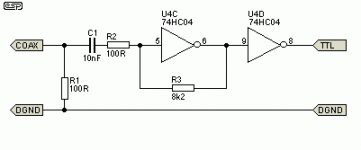
3. A few other input circuits use two inverters to boost the COAX to TTL level. I'm wondering why the need for the filter, why not use a single op-amp?

Attachments

  • p85-f5a.gif
    p85-f5a.gif
    1.7 KB · Views: 757

For Sale 2x 4CH Purifi Amplifiers for Sale

I have 2x 4CH Purifi Amplifiers available for sale.
I bought these from VTV last year.
https://vtvamplifier.com/product/vtv-amplifier-four-channel-purifi-audio-1et400a-amplifier/


I had cleaned up the internal wiring and layout of the units.

  • Each unit has 4x Putifi 1ET400A modules
  • 2x Hypex SMPS1200A400 SMPS
  • Hypex OEM input buffers.
  • I added Hypex HxR regulators on the input buffers
  • There is a low noise pre-regulator feeding the input buffers
  • Additional shielding between the SMPS and modules.
  • Speaker output on Speakon connectors, Balanced XLR inputs
  • Does not have 12v triggger
  • Does not use input EMI filters (as recommended by Bruno)

Asking $1500 for each unit + Shipping (will ship within US). Also available for pick up in San Jose, CA

I will add some pictures later this evening.

Opto coupler??

Good morning,

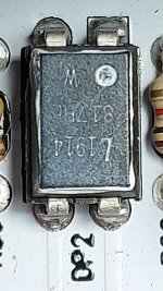
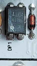
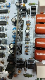
I'm pretty sure DP1 and 2 are opto couplers... but I'm having trouble locating the proper part. There is a 1914 and 817 written on them.

If someone could point me to the proper part or a reliable substitute, that would be great!! Thanks!

Attachments

  • 20220529_104541.jpg
    20220529_104541.jpg
    254.1 KB · Views: 102
  • 20220529_104703.jpg
    20220529_104703.jpg
    248 KB · Views: 103
  • 20220529_104811.jpg
    20220529_104811.jpg
    371.9 KB · Views: 95

JBL M2 DIY Plans Search

Hi everyone,

I've gotten a great deal on JBL M2 parts.
Therefore I'm looking for plans or construction drawings from people that have already made clones.
I've tried messaging Cyril on youtube, POS, PBN Audio, and Leslie on audioheritage.com. I've also found an account I believe belongs to Leslie on AVS Forum.
But I haven't gotten any replies.

Do you happen to know either where there are plans posted, have a copy, or could get me in touch with anyone that has plans?


Thanks advance.


Niclas
Projects by fanatics, for fanatics
Get answers and advice for everyone wanting to learn the art of audio.
Join the Community
507,645
Members
7,882,587
Messages

Filter

Forum Statistics

Threads
405,959
Messages
7,882,587
Members
507,645
Latest member
Tahoephoto