Orion cb3500.1d questions

OK so I'm new here an I'm upgrading my amplifier in my car an I've ran into a few questions I'm replacing a Sony XM XMZR1252 800 watt amp with a Orion cb3500.1d I my first question is the amp didn't have a bass knob when I bought it an I checked the only audio shop around me an all they would tell me is call orion an I've tried to an can't reach anyone it's a 3.5 mm audio jack looking input an I was wondering what kind of gain control bass knob would work with it I was told only certain ones would others may harm the amp. Secondly what size wiring harness should I get for this amp the Sony was a 4 Awg an I know that's to small for my orion ishould run 0 awg with this new amp correct? Any help would be appreciated thanks!!!

Polyfill in vented box for fullrange Markaudio CHR-120 driver

Title sort of says it all.

What's the general consensus on loose polyester stuffing in vented boxes, for a Markaudio CHR-120 driver ?

I've built an enclosure identical in volume to this 56 liters box :
https://www.kjfaudio.com/wp-content/uploads/2020/04/CHR120-classic-vented-box-standmount-large.pdf

Yay or nay for Polyfill?

Thank you all.

Best Ever Headphones: Sony MDR-V600? (don't laugh!)

For years I found that even though I wanted to listen to music in settings where headphones were the only viable format, I just couldn't tolerate my meager setup for longer than a half-hour at best. Decades old Sony MDR-V600 headphones driven by an old HeadRoom Total Airhead amp, plugged into the 1/8" output of my Samsung Galaxy S7 phone. But as time went by and I learned more and more online about the wonderful world of analog audio, I became aware of two major flaws in my setup. One I was fortunate to realize by happenstance: because the ear pads had broken down so much over the years that it got to be so bad that the headphones started to hurt my ears by way of the inner planar surface smashing my earlobes down, I was driven to order replacement ear pads (I had to cut the old ones off and glue these on). Turns out that the broken down pads had altered the sonic performance in a very negative way that I hadn't realized.

The other flaw was one that is probably obvious to most readers here: using the phone's DAC. I knew too little to know that this could be a shortcoming. I was fortunate enough to discover Schiit Audio and find my way to the Modi Multibit DAC (NOT the Modi 3, rather this is the almost 3-times-as-expensive mulit-bit version, and I will never ever listen to a Delta-Sigma DAC again after falling in love with mult-bit decoding). I'm now playing Spotify on my laptop through the DAC (still using the old HeadRoom amp) playing 320 kbps Ogg format (Ogg is Spotify's native format, one that I HIGHLY approve of despite its poor online reputation for no other reason than that it's not a "modern" codec). I now can listen to headphones and actually enjoy it, which leads me to my primary reason for starting this thread.

So in the meantime I have tried two different models of headphones to compare to the very old and discontinued Sony MDR-V600. These are the MDR-7509 (not HD, but I don't know what the "HD" version actually adds, if anything) and the Beyerdynamic DT770M80. Both come nowhere close to the V600, which is why I sought out and purchased yet another (used) pair of V600's on Ebay which I was very fortunate to find in decent condition, almost like-new when compared to my very used old pair.

The 7509's have way too much low bass and more disturbingly are very hollowed-out in the low mids, and the latter shortcoming is not one that I can tolerate, as low mids are the principal reason why I bother listening to music in the first place (add crisp highs above 10k and I'm that just much closer to heaven itself). The Beyer's had very nice sounding highs but the middle of the mids sounded like they were being transferred through amplified empty soup cans (in other words emphasized and not in a good way).

So I'll stick with my V600's which I adore, but I wonder why they have such a poor reputation online? I thought about trying the 7506's but after reading quite a few reviews I was discouraged by their apparent shortcoming in bass and low-mids.

Here is one comment on the V600's that I did find in this forum, albeit from almost 10 years ago (in an old thread entitled "Reference headphones"):

Fair Enough...
I have both a MDR7505 and MD-V600. Both sound decent, but myself prefer the 7505s as with increased pressure they block out external noise a lot better.
My wife on the other hand has been using the V600 for a while ( about 3 years now ) and she wont part with them.

But... if your good at seeking out deals you can find them around $400 for the HD 650's 😉

Now in the interest of being totally transparent, I will confess to a bit of an EQ preference I have applied to the V600's using Equalizer APO's 16-band linear: -3 dB on 63 Hz and -2 dB on 10 kHz. Very modest compared to what I would end up having to do to try to make other phones listenable.

ECC83S/12AX7 Omitting grid leak, input impedance and preamps

Hey guys
I've acquired a diy push pull tube amp based on ecc83s and 6l6gc. Was initially made to take in balanced signal, shorted it to be able to use unbalanced. Been studying it for a while as I do not come from the electronic engineering background.

I want to build some sort of a volume control for this amp.
One of the options is to go with a passive pre amp but for that I need to understand how to match the impedance in order no to mess up with the high frequencies.

There is one interesting design feature of this amp that it does not have a grid leak resistor on the gain stage, just a grid stopper. Now naturally the input impedance is approximated by the grid leak value, but how do you calculate it when there is no grid leak resistor?

I am afraid that without having a grid leak, anything I will put on the grid will add up to grid stopper resistance, right? Does this mean that passive pre-amp is not a viable option and I should build a buffered one? Or does that mean that only a small value pot would work right, such as 10k

I've attached the gain stage circuit for clarity. Please let me know if there are any issues with the drawing. This was the very first circuit I've drawn in my life.

Attachments

  • Screenshot from 2021-07-07 14-06-17.png
    Screenshot from 2021-07-07 14-06-17.png
    11.3 KB · Views: 456

T/T DC Motor Pod & Power Supply upgrade unit (better than the O/L version)

Downsizing house so time to downsize toys. T/T motor pod & separate Power supply. Unit can be easily upgraded by using 14 VDC SLA battery, exactly as VPI does. Motor is capable of driving a sub plater like that used on the Rga T/T to a 14'' platter periphery. Has fine adjustment via potentiometer screw in the P/S. Using with a 12'' platter it allows for either 33 or 45 RPM to be dialed in. Various belts could be used, from a standard rubber belt, a string belt as used by WTA, or as I use a Mylar belt which gives the best performance. Motor pod as adjustable feet which allow various T/T platter heights to be accommodated. Previous this I used an Original Live unit, but this motor is much better, now I have upgraded again to a Maxon DCX 22mm motor & controller as used by Kronos on their high end T/T's

Price US$350 plus P/Pal fees of 3.5%. (Postage worldwide US$70 tracked or US$40 untracked)

Attachments

  • 1128211048a.jpg
    1128211048a.jpg
    237 KB · Views: 127
  • 0530220941a.jpg
    0530220941a.jpg
    308.9 KB · Views: 129

Box resonance according to DATs v3?

I just picked up a DATs v3 to measure the port tuning of a large enclosure I built for my Lavoce 18" sub. Running an in-box impedance sweep though is showing a huge blip at 74Hz.

1654698560811.png


Driver: Lavoce SAF184-03
Volume: 17.3cf (76in L x 44.5in W x 10in H)
Tune: 14Hz
Port: 5.125in x 9.25in x 35in

One thing I discovered is that placing a pillow in the center of the box, along the width eliminates the peak. Though it also reduces the impedance a lot (by about half). Not sure what this means overall.

1654700169597.png


Here is my WinISD measurements before and after the pillow (you can see the 74Hz dip disappear)

1654700360972.png


Also I was going for a 14Hz tune, but DATs is showing about 12.5Hz. Should I think about shorting the slotted port I built into it?

AUDIOMOBILE LIVES in 2022!!!!

SUCCESS!!!!!.... My THEN & NOW amp rack is nearly complete. Works great, cool runner now for FANS and soon the MINISTRY test to see where they stand. 1977 SA-1000 x3 and 2x PA/BDBD BE THE BIGDOG Class D 700 watt BASS amps. About 2000 watts in the old Firebird today. RUMBLES the car and very crisp sound from them SA-1000 amps... I installed the SP-300 in the CIGGERETTE ASHTRAY slider.... slides right in.... no mounting etc..... slips right into the GM ashtray mount in the dash.... OLDEST SCHOOL.... BDBD/2022

Attachments

  • IMG_0214.JPG
    IMG_0214.JPG
    333.5 KB · Views: 89
  • IMG_0215.JPG
    IMG_0215.JPG
    247.5 KB · Views: 97
  • IMG_0216.JPG
    IMG_0216.JPG
    351.3 KB · Views: 94
  • IMG_0217.JPG
    IMG_0217.JPG
    307.2 KB · Views: 95
  • IMG_0218.JPG
    IMG_0218.JPG
    439.4 KB · Views: 93
  • IMG_0219.JPG
    IMG_0219.JPG
    202.4 KB · Views: 84
  • IMG_0220.JPG
    IMG_0220.JPG
    203.5 KB · Views: 87
  • IMG_0221.JPG
    IMG_0221.JPG
    377 KB · Views: 91
  • IMG_0222.JPG
    IMG_0222.JPG
    369.6 KB · Views: 89
  • IMG_0224.JPG
    IMG_0224.JPG
    251.3 KB · Views: 94
  • IMG_0225.JPG
    IMG_0225.JPG
    275.2 KB · Views: 94
  • IMG_0226.JPG
    IMG_0226.JPG
    474.6 KB · Views: 87
  • IMG_0227.JPG
    IMG_0227.JPG
    654 KB · Views: 90
  • IMG_0228.JPG
    IMG_0228.JPG
    569.5 KB · Views: 95
  • IMG_0229.JPG
    IMG_0229.JPG
    628.7 KB · Views: 87
  • IMG_0230.JPG
    IMG_0230.JPG
    533.1 KB · Views: 86
  • IMG_0231.JPG
    IMG_0231.JPG
    418.4 KB · Views: 95
  • IMG_0232.JPG
    IMG_0232.JPG
    488 KB · Views: 86
  • Like
Reactions: oPossum

Vintage Aztec speaker

My Dad bought these speakers in 1969. Aztec Loudspeakers of Denver Colorado, the model is the "Monet". I remember growing up with these speakers. My Dad was a professional musician at the time, these bad machines would play loud and clean...

...and he still uses them !... I recently gave them a listen and they still sound good. Sometime I will have to measure them with my omnimic and see what the frequency response is...

The cone tweeters have been slightly abused by grandchildren fingers...

Attachments

  • 20200220_165153.jpg
    20200220_165153.jpg
    749.2 KB · Views: 676
  • 20200220_165226.jpg
    20200220_165226.jpg
    666.5 KB · Views: 681

Tube amplifier stability question

I have an amplifier which exhibits a form of instability I haven't seen before.

If I slowly ramp up a test signal, and then slowly turn it down, everything looks great.

If I turn it up to clipping, and then quickly turn it off, the amplifier starts to oscillate at a subsonic frequency, the line on the oscilloscope bounces up and down until it does out

The size of the cathode bypass capacitor on the input tube seems to affect the amplitude of the oscillations. When it is large, the amplifier can breaks into a high amplitude oscillation. At the stock capacitor size, it needs to be provoked as described above.

There is no evidence of high frequency oscillation.

Any suggestions to troubleshoot this? I would like to improve the performance of the amplifier such that it no longer oscillates.

Geloso G-257. From sixties magntophone to guitar amplifier.

Hello, this is the second time I try the modification on this little italian tape box with an amp section design similar to a Fender champ, but still no luck.

This is a very popular modification in Argentina, it's been around for decades and thanks to the common language and the rise of the internet it became also popular in Spain.

In this case, I've partially succeeded, since I can hear the guitar coming out from the speaker but at a very low volume. It should be much much louder. I've tried with spare tubes which should be ok and still no luck. What else should I look at? The web is full of information about it but there's insufficient troubleshooting discussion.

I need some expert advice before starting to pull cables off and screw it up again, just as I did with the first one. I guess some guide prioritizing what components to discard first as faulty would be the way to go here. Capacitors look ok but that could be the case. I also detected one of the cables going to the preamp tube that if touched shuts any outgoing sound, but that shouldn't be the main problem. As I said, it lacks POWER.

I've also realised that the speaker pins + and - have continuity (shortened) but after some research that seems to be normal in amps with an output transformer.
I'm dying to test this amp at full potential with my new strat and some pedals, help me please!!

Here is the circuit diagram.
GelosoG257Schem.jpeg

I'm going to start by checking voltages and see what comes out...

Here are some videos 1, 2 , 3, 4 on its performance as a guitar amp, the modification and some history on why was it initially modded over there (in Spanish).
P.D. Some even add an FX Loop to it and as to deactivate the power amp section ... But I guess that are parts two and three...

Attachments

  • Geloso+G257+Tape+recorder.jpg
    Geloso+G257+Tape+recorder.jpg
    110.9 KB · Views: 245

Bobs Cordell's Super Gainclone LM3886 - trying to simplify

Hello all,

I am having this idea to simplify the original Cordell's Super Gainclone schematics. In particular, I want to get rid of servo circuit and add capacitor instead.

Attached are the original schematics from the book, my version, and LTSpice simulation file.

Any comments are welcome.

Attachments

Rockford Fosgate Power 400a4

Hello all,

I am working on a Power 400a4 PC-2527C.

One power supply FET was shorted, replaced all 4 with IRF3205s and 47 ohm gate resistors. Also replaced 2- MMBTA56s (Q2 and Q3)in the power supply

RCA shield grounds broken. I have repaired them.

Crossover switch for Channels 3xx and 4xx broken, currently have switch removed and jumped for all pass.

Problem now, I am having trouble with setting the bias on the 400 series channel (left rear).
When I try to set the bias by monitoring voltage across the source resistor it starts at 0.060 mVdc and slowly climbs to 0.080 mVdc then suddenly, with the slightest movement jumps to ~3.4 mVdc. When I try and reduce the voltage by turning the pot back ccw , the voltage increases. If I turn it full ccw then cycle the remote it resets to 0.060 mVdc.

I have checked every 4xx resistor and they appear to be within tolerance, or at least match the other channels.
I have checked all transistors and diodes for shorts or open and they all seem fine in the 400 channel.
I have also cleaned the bias pot RV 404 with DeoxIT.

On the schematic 4xx is listed as right rear but in my amplifier it is tied to left rear output.

I am stumped. Where should I go from here?

Attachments

  • Power 400a4 Board.jpg
    Power 400a4 Board.jpg
    740 KB · Views: 413
  • Power 400a4 Channel 4xx.jpg
    Power 400a4 Channel 4xx.jpg
    475.2 KB · Views: 261

Dot codes on tubes?

Hello everyone.
I found a dot matrix code following the part number or name in several tubes (mainly of the compactron kind but not exclusive). Mostly in newer units. Does anyone know what it mean?
It seems to be independent of the manufacturer (RCA, SYLVANIA, DELTRON).

Attachments

  • 20220610_105035~2.jpg
    20220610_105035~2.jpg
    133.8 KB · Views: 94
  • 20220610_104546~2.jpg
    20220610_104546~2.jpg
    143.6 KB · Views: 98
  • 20220610_104401~2.jpg
    20220610_104401~2.jpg
    99.4 KB · Views: 97
  • 20220610_104524~2.jpg
    20220610_104524~2.jpg
    133 KB · Views: 98

PRV Quality

Anyone have experience with PRV woofers and full range drivers? How do they compare quality and performance wise to other budget oriented drivers? 15W700 for example looks pretty nice for a budget driver if it has decent sound and build quality. I notice a lot of folks using their CDs but not much about the direct radiators.

Hafler IRIS output level question

I finished recapping an IRIS preamp. All new electrolytics, all the tantalums swapped for electrolytic as well. As I put some hours on it the sound is coming along nicely but I notice that the output level is a lot lower than any of my other IRIS preamps at the same volume position. I have to turn this one up past halfway to get it to normal/loud listening. The bass seems a bit more rolled off as well.

No distortion so I don't think I have any failed parts. Is there a way to raise the output? Maybe those 4 adjustment pots that I see on the mainboard?

Can increasing the coupling cap, decrease low bass response in case of GNFB??

Hello, I'm just simulating a SE tube amplifier with quite heavy GNFB, and, under simulation, if I decrease the interstage coupling cap (from 470n to 100n with R=150K), I get a slight increase (+0.5dB) in the low band bass response (< 50 Hz).
If I decrease to 1/10, 47nF, I get even a slight peak around 20-30Hz.

How this can be possible?
Are these still good basses?

This is only applying the GNFB. Without GNFB, decreasing the cap value, I decrease the low band frequency response, as I was expecting.

CDM 4/11 vs CDM 4/19

Hello all,

First off, like a good boy, I have searched. But I have still not gotten all the information I need.

I here today asking about the differences between the 4/11 and 4/19 CDM mechanisms.

From my research here, all I can tell is that the 19 is the 'standard' version while the 11 is the 'hall motor' version. Can anyone tell me what 'hall motor' means? Is this a better motor?

If someone could point out any other differences, I would be most grateful.

Cheers! 🙂

Advice on EQ using a Mackie CFX12

Hi,

I am trying to make our female vocalist sound clearer using our mackie CFX12 mixer.

I have found many web sites suggesting which frequencies to cut/boost but not sure how to do this using the Mackie.

For instance one site suggests.

Cutting 300hz to 350hz as first step
Cutting 600hz as second step
Cutting 150hz to 200hz as third step
Applying low cut (Which on the mackie cuts everything below 100hz)
Boosting 6k

I understand how to cut and boost but the mackie only has 4 pots on the strip the first one cuts and boosts 12k
the bottom one cuts or boosts 80hz and the middle one cuts or boosts between 100hz and 8k so most of the above suggestion are in the range of this pot but I can only pick one frequency to cut or boost ?

Am I missing something ?

The mackie also has a slider EQ but modifying this changes the whole of the desk and not just the female vocals (we have drums, bass guitar and Lead guitar running through the desk)

Any help would be most appreciated.

Cheers in advance

VFD tube clock

I am going to build a clock with IV-11 Nixie VFD Tubes. Now I understand I need 25V or so for the tubes and 1.65V for the heaters. The problem is I wish to use the 60KHz MSF signal to synchronize the clock. This requires a quiet supply. So looking for some suggestions on generating the supply voltages. If I use a switching supply if it runs higher than 60KHz will that still generate noise at 60KHz or should it be completely linear. I would also like the display to dim at night. I am not going to multiplex the display as that will create noise. Dimming would be be either reducing the HT supply or change the grid voltage. This is the RX and contains a 60KHz crystal as filter and a ferrite rod antenna.

https://www.amazon.co.uk/60kHz-Atomic-Clock-Radio-Receiver/dp/B01KH3VEGS

Balanced and Unbalanced Inputs?

I've just been mulling over my options with preamp builds, specifically how to allow for balanced inputs to a pre-amp that is not internally balanced (and keep the CMR). E.g., provide balanced inputs for a B1 Korg. I've read the Jensen essay on this kind of thing and know I can use an input transformer for this purpose.

But what if there are other inputs that aren't balanced? Let's suppose I've got two balanced and two unbalanced inputs. Can I just connect all the inputs to a 4 pole selector switch and ground 'pin 3' for the RCA inputs? then feed the output of the selector into the transformer? Obviously, this would preclude any kind of attenuation of the balanced signal. (I suppose a -6dB switch could be added.) Is that OK too? Or is there some other way to do it?

Riki

DIY vintage floor-standing speakers

Hello!

Sometime ago a friend asked me about designing a floor-standing speaker that should have some kind of “vintage sound signature”!

Since I’m familiar with Visaton speakers due my former collaboration with their dealer in Greece, I decided to go with W-300, W-170, Μ-10 and TW-6NG in a 4-way design.

The friend who built the speakers commented that the sound was very "involving" and "lifelike". The bass was nothing close to boomy despite the vented-box reputation among a fraternity of audiophiles who declare it as “single note’’ bass.

He said that the listening had traveled him back to the finest sounds made by large American speakers of the early golden-era of Hi-Fi.

If someone has worked on a similar design I’d be glad to hear his comments.

Attachments

  • Thank You
  • Like
Reactions: aroS3 and GM

Tube tape repro head preamp for Tandberg TD20/10XD Reel to Reel

Hi Guys,

My first post here but long time reader.

I've recently moved to tube pre/amp and phono stages and I like the sound. I'm not an audiophile and I did it mainly as a covid project and surprisingly had great results. Build a phono stage based on Tavish vintage design and I was thinking to also build a tape head preamp to feed into a tube amp (Willsenton R8 with min 100KOhm impedance). The existing solutions are outrageously expansive and probably overkill for my setup. I'm more of a DIY kind of guy, that's why I got into R2R and tubes.

Does anybody have any experience with older tube r2r or receivers that accept tape head inputs? I understand that head inductance has to be matched with the preamp so the first question is:

- does anybody know what the inductance of the PB head of Tandberg 10XD/20TD (Ferrite) and if it would work with any of the older tube amps?

Also, I've been looking at the following amps and r2r tape head preamp section as inspiration and wondered if any of you have any experience preference on performance:

- Marantz 7 (Tape head input)
- Fisher 500C (Tape head input)
- HK A500 (Tape head input)
- Revox G37 (tape head preamp output)
- Tandberg 64x (tape head preamp output)
- Tandberg 74B (tape head preamp output - 1st stage transistor followed by 2nd and 3rd in tube)

I'm assuming the 3 receivers pre is more generic allowing a larger tape head compatibility but there isn't much info out there. The r2r pre are probably more specific to the heads used in those machines.

Any suggestions or information is greatly appreciated.

Again, I'm not looking at studio grade, just to add tubes and have good results, not worst than the r2r internal preamp.

Thanks

PCB for bi-polar caps/bridge rectifier (for Pass Pearl 2)

These PCB's were made for the Pass Pearl 2, but can be used for many other power supplies.
Room for:
* Dual bridge rectifiers
* CRC snubbers (Quasimodo)
* Dual snap-in caps
* Dual terminals for V+, V- and GND
* Bleeder resistors for caps
* 2 LED's with current limit resistors.
* Slides into Hammond 1455 cases for a nice compact PSU

Tested this with my own Pearl 2 and it works nicely
I have 7 boards available.... $15/ea includes shipping/fees in CONUS.

Attachments

  • 2021-03-29 16.43.57.jpg
    2021-03-29 16.43.57.jpg
    282 KB · Views: 377
  • 2021-03-29 16.44.03.jpg
    2021-03-29 16.44.03.jpg
    224.1 KB · Views: 367
  • 2021-03-04 00.19.08.jpg
    2021-03-04 00.19.08.jpg
    247.3 KB · Views: 361

Six order quarter wave parallel?

Here’s an option that seems to work much unlike other things that don’t quite simulate the same as they end up. Mostly getting rid of the nasty face section in the top of bandwidth and things like p@r@flex…

Sure is’weird’ what you get Play sweeping across from the short side to the long side and the baffle that separates them right at the exit, different individual tones and beat frequencies..

It’s like sweeping across the front of a MTM slowly all the sudden when you go by the tweeter and then back to the M

I guess part of it is an individual resonance part of it is whatever tone fits in one of the three same resonators, and the split between the two when it’s a velocity max for both???

/0.625=13824
/.125 =6912

345.6/.25/4 = 345.6
/5 = 172.8
/1= 86.4
/2=43.2
/4=21.6
/8 = 10.8
/16=54
/32= 27
/64=13.5

Attachments

  • BE20A94B-9751-43C0-819E-961E95976B7A.jpeg
    BE20A94B-9751-43C0-819E-961E95976B7A.jpeg
    425.8 KB · Views: 108
  • 69AF9E21-3947-48D9-8A20-833C0B3F40FA.jpeg
    69AF9E21-3947-48D9-8A20-833C0B3F40FA.jpeg
    521.1 KB · Views: 107
  • 2390E7F0-D9EA-4F9F-86B8-ADA91E41B20A.jpeg
    2390E7F0-D9EA-4F9F-86B8-ADA91E41B20A.jpeg
    387.8 KB · Views: 107
  • A841FEC3-D77A-41B0-B561-08D59CA3A592.jpeg
    A841FEC3-D77A-41B0-B561-08D59CA3A592.jpeg
    367.9 KB · Views: 90
  • 2D643BFB-6624-4E94-A097-5976E57086D9.jpeg
    2D643BFB-6624-4E94-A097-5976E57086D9.jpeg
    368.7 KB · Views: 103
  • 810DDCC3-CBB9-4538-A738-F3B590A34ADE.jpeg
    810DDCC3-CBB9-4538-A738-F3B590A34ADE.jpeg
    408.4 KB · Views: 102
  • ED925ADC-942A-4B79-9636-F374B3DA57F7.jpeg
    ED925ADC-942A-4B79-9636-F374B3DA57F7.jpeg
    436.3 KB · Views: 121
  • image.jpg
    image.jpg
    643.6 KB · Views: 110
  • image.jpg
    image.jpg
    483.7 KB · Views: 109

Guidance for Forte Audio Model 40 Preamplifier DIY power supply

Zen Mod directed me to open up a separate thread for this one.

Basically,

I have a Forte Model 40 with no power supply. I've included pictures of the on board regulators (7815/7915 types) and of the power adapter cable that is hardwired to the preamplifier (Tajimi 3 pin). These seem to share a bit in common with Threshold units of the time although I don't think this particular one was designed by Mr. Pass if my research is correct.

I can't seem to locate the proper Tajimi connector so I assume I'll likely have to get a different type for this project. I really want to come up with a power supply that is at least as good as the original. Any help/guidance would be greatly appreciated!

Attachments

  • 194170500_841508563173479_897766572211946749_n.jpg
    194170500_841508563173479_897766572211946749_n.jpg
    239.7 KB · Views: 340
  • 195182420_213704873927062_9122951731074969529_n.jpg
    195182420_213704873927062_9122951731074969529_n.jpg
    278.4 KB · Views: 394
  • 195505987_3889118657881817_7600960045306076681_n.jpg
    195505987_3889118657881817_7600960045306076681_n.jpg
    227.6 KB · Views: 564
  • 193566505_3003928806521084_1098706031464348847_n.jpg
    193566505_3003928806521084_1098706031464348847_n.jpg
    241.8 KB · Views: 320
  • 195203156_209775910968506_4262522469503545376_n.jpg
    195203156_209775910968506_4262522469503545376_n.jpg
    189.2 KB · Views: 344
  • 197854269_324773129211977_8354338140294350716_n.jpg
    197854269_324773129211977_8354338140294350716_n.jpg
    368.4 KB · Views: 290
  • 199643017_1068375453689999_3662922794739973899_n.jpg
    199643017_1068375453689999_3662922794739973899_n.jpg
    430.7 KB · Views: 302

Temaad Warlock 12'' Uni-Pivot tone arm - Silver wired

Offered is my Temaad 12.5'' Warlock magnesium wand uni-pivot tone arm with removable Head-Shell, I have upgraded to the Titanium Merlin arm

So ideal for your SPU - Decca - Koetsu - A/T 33 & of course 103.

Arm comes with full detailed set-up instructions, also Gold plated RCA outs

The arm will be wired with our propriety 34swg silver tone are wire, this wire is way better than Cadas & in our opinion about 80-85% as good as the super high end VDH wire.

Should the purchaser want to go for the best then we can re-wire with high end VDH MCS 150M silver wire (many people rewire their SME V with this wire) for an extra $200. (Hadcock used to charge $600 for this service)

Physical parameters
-Effective length 305 mm
-Mounting distance 300 mm
-Suggested Overhang 12.5 mm
-Offset angle 16.8
-Effective mass 18 to 24 gms; (depending on head-shell fitted)

Price US$550-00 plus P/pay fees of 3.5% - postage world wide : US$95 tracked or US$40 non tracked. (can be sent labeled say "as in need of repair at a cheaper value to help to save on any import tax applied)

Note Arm pod not included, but can be sold separately

Reviews for the manufactures web site


Peter - Sorry it’s taken me so long to get back to you but I’m getting very good results with your arm. My guess was good with my ZYX Omega: it works very well with this arm - I’ve had problems in the past with the lightweight SME V & other medium mass arms

Bruce - So I can’t say definitely why because I’ve never had a Mayajima mono cartridge, but there is something that sounds very “right” about playing my old mono jazz and classical records with your arm & the Mayajima. The horns have a bite and an “in the room” presence that I don’t get from my ZYX Optimum

TNTAudio - G.Husband. I've long admired 12" arms, but they are invariably expensive & need a compatible turntable. Well with this kit you get a 12" arm for a 9" price. The arm reminded me strongly of the Morsiani, so that is very high praise, as I consider the it can lay claim to the Best Sounding Arm in the World.

Chriswhgree - Fantastic, Initial results were excellent-more open & relaxed than many arms-I've owned just about ever one you could think of ? - Ittock ($3,000), N/Analogue (2,500), UP4(2,400), Opus 3 (1,950), C/audio Satify ($2,350)

rmoonknight - I just wanted to say it sounds great. Very smooth & big. Thanks so much for a great, affordable product. It's amazing to me how it sounds better than my Jelco.

Attachments

  • 0815211236aHDR.jpg
    0815211236aHDR.jpg
    349.3 KB · Views: 183
  • 1121201642.jpg
    1121201642.jpg
    215.2 KB · Views: 201

I need help for upgrade my mini USB powered amp

hello.
Some time ago I bought a portable amplifier for my work that works with power from a USB port (5v-20v).
I also bought him a power converter from 5v to 12v. to make it work with a little more power.
I bought all this on aliexpress for a few dollars.
sounds decent for the price. but I want to take it further for fun and experiment.
I already changed the op-amp. It came with a ne5532p and I put a muses02 on it. the sound improved noticeably.
now new capacitors are about to arrive (nichicon KW and some nichicon film to put them in parallel to the KW. I wanted to put some KZ but they don't fit).
I would also like to change the transistors and this is the reason for this thread.
Since the op-amp and capacitors it originally comes with are low-medium quality, I'm assuming the transistors are too.
It has 1 transistor D882P and 5 transistors of a plastic material in which only a letter K is distinguished.
transistor D882P is NPN. the others I don't know...
which audio transistors would be the best replacement for my low voltage mini amp?

also the power supply (the 5v to 12v converter) picks up some noise when my laptop is connected to the charger even though i bought a usb isolator (ui501) for it.
the isolator block some of the noise but not all of it. The noise is felt when I use headphones but not on speakers.
I changed a couple of capacitors, but the noise is still there. maybe placing some capacitors in parallel can fix something?.
any advice?

I attach the links of both products:

Douk Audio U3 mini amp:

https://es.aliexpress.com/item/1005...f16512738927277811e015e|12000017626492931|sea

Converter 5v a 12v:

https://es.aliexpress.com/item/3300...816512741597555192ea1d8|12000018800586971|sea

usb isolator ui501

https://es.aliexpress.com/item/4000..._list.0.0.21ef194dceDFe8&gatewayAdapt=glo2esp

I attach photos too.
hope you can help me.
sorry for my grammar i'm not native english speaker.

Regards.


IMG_1722.JPG


IMG_1734.JPG


IMG_1741.JPG

Class D or FirsWatt/Aleph

Ladies and gents,
i am a little bit in trouble.... 🙂 🙂
After 10+ years i am back in audio ... Many things changed and i feel kind of lost.
...
Before, it was kind of easier - class A, Class AB, tubes.... done more or less....
.
Now, we have class D that looks kind of promissing....
But, i have doubts related "lifeless sound", to much power i really don't need, reliability question in function of time,...
I mean - tube amp will work probably for decades and i am not sure i can say that for class D from my standpoint.
.
To cut the story short.
I am having speakers that are 90+ db on 4 ohms....
Listening to electronic music mostly (ambient and such).
can do tubes for peamp section
BUT
can anyone tell me if i should consider class D or maybe better go for F5 for example..... or maybe Aleph 3....
i kind of like classic circuits - makes me feel more comfortable... but still like to get the most for the money invested.....
...
i know it is one of "those" threads... but stil, when you feel "crazy" from so many things around you, a brother with a little bit wider perspective would be nice to hear....
Thank you all for your time and advices.....
cheers

Tribute Bands

Some people like them, some don't, some think the concept is bizarre, but I quite like 'tribute' bands if they're good. Since no-one is ever going to see Pink Floyd, Hendrix or Led Zeppelin live again, maybe these are the next best thing.

There might be a blurry line between 'tribute' and cover'; for example, Heart did great covers of Led Zeppelin songs, but you'd hardly call them a 'cover' or 'tribute' band, any more than you'd call The Beatles a Chuck Berry cover band, but I've linked Heart;s version of 'Stairway' anyway because it's great.

I think these are well worth an optic:

Fleetwood Mac (Rumours of Fleetwood Mac)

Login to view embedded media
Pink Floyd (Brit Floyd)

Login to view embedded media
Heart

Login to view embedded media
Led Zeppelin (Zepperella)

Login to view embedded media
Jimi Hendrix (Randy Hansen Band

Login to view embedded media
What say you?

Geoff

Can you add internal bracing to commercial speaker?

My question is

can you add internal bracing to an already made pair of speakers?
would it alter the sound in a bad way or in a way the speaker designer didn’t have in mind?

i was thinking of adding low mass aluminum rods inside in a cross pattern to increase stiffness of the cabinet.

im assuming it would ruin the sound of the speaker the way it was designed from the woofer selection and crossover the designer used?


thanks!

STK 0040 II BIAS HELP

Good Night (for these latitudes).
I have purchased an AIWA P30 power amplifier. I have made measurements in dc output and bias current.
It has a pot to adjust the DC output but not to adjust bias.
The polarization current measurements give 6.5 mV for the left and 3 mV for the right.
The output is with STK 0040 II.
In the service manual it does not say the correct value, but it seems low to me apart from being with asymmetric values.
The integrated circuit STK 0040 II has the possibility of adjusting bias?.
Thank you very much.

UAF42 Universal Active Filter

Hi folks


I have obtained some Burr-Brown UAF42 Universal Active filter ICs and am thinking of using one to make a LFP to use in the output stage of a DAC.


There is almost no mention online of these chips being used by anyone, so I'm wondering if anyone here has any experience of them?

There is a detailed application document on it's use: www.ti.com/lit/pdf/SBFA002


It looks like a very useful chip and ideal for the application of filtering the analogue output of a DAC, it even has an extra opamp onboard that could be used as a unity gain buffer after the filter.

What frequency should be used for such a LPF - 20kHz or slightly higher, say 24kHz? Which of the filter types supported by this chip would be most suitable? I'm guessing a Butterworth, but I really don't have much knowledge in this areas.

Attachments

  • uaf42-1.png
    uaf42-1.png
    216.7 KB · Views: 365
  • uaf42-2.png
    uaf42-2.png
    172 KB · Views: 343
  • uaf42-3.png
    uaf42-3.png
    141 KB · Views: 318
  • uaf42-4.png
    uaf42-4.png
    66.4 KB · Views: 324
  • uaf42-5.png
    uaf42-5.png
    228.1 KB · Views: 309
  • uaf42-6.png
    uaf42-6.png
    120.2 KB · Views: 210
  • uaf42-7.png
    uaf42-7.png
    115.2 KB · Views: 204
  • sbfa002-1.png
    sbfa002-1.png
    250.9 KB · Views: 204
  • sbfa002-2.png
    sbfa002-2.png
    288.1 KB · Views: 161
  • sbfa002-3.png
    sbfa002-3.png
    254.2 KB · Views: 182

Philips CD 9 Pro replace?

Hi all,
I read a topic reffered to the philips cdm 9 pro mechanics in the forum http://www.diyaudio.com/forums/showthread.php?s=&threadid=14068&perpage=25&pagenumber=1
and need contact with ohynot (because they have units for sale), anyone have the mail, I can read the link.
Others users have spare philips cdm 9 pro mechanics links or where can find one.
Thanks for your time!
Rubén

Virtual OTL SE amplifier idea

The OTL configuration has obvious advantages, but it is not very practical with "regular" tubes and speaker impedances: to push a reasonable output power into a 4 ohm load requires largish currents, huge tubes tolerating amperes of cathode current, meaning they also have a large plate dissipation, and because of the voltages involved in tubes circuits, the output power is also gigantic.
This is not very convenient, and 800 ohm speakers were a niche, limited to some TV sets and record players.

Here is a possibility to fake an OTL, without actually enduring all the consequences. It is not perfect, obviously and requires a transformer, but the topology makes the transformer almost invisible.

The example I provide has been actually tested, but it is not meant to be a complete, finished project: it is improvised with what I had handy, and to make a real, buildable project, you need to do your own work.

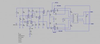
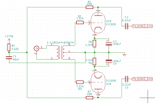
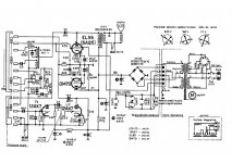
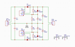
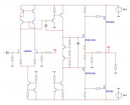
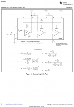
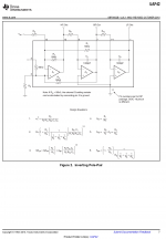
Here is the circuit:
VirtOTL.png


The output stage is a cathode-follower, directly driving the load. Of course, the transconductance and the maximum cathode current are too low to drive a regular load. This requires a trick, in the form of a transformer.
The primary of the transformer is in the anode circuit, where it senses the excess current required from the cathode and provides "assistance" via the stepped-down secondary.
Note that it is an actual follower: you could argue that since the same excitation current flows through both windings in series, it is simply an autoformer rearrangement of a conventional plate-loaded stage, but this circuit is always a follower (ideally at least), and even if you alter the turns ratio, it will always tend to a gain of 1.
In practice, with a weakish tube like the ECL82 and a non-optimal transformer, it is rather far from unity gain (much lower), but it does work.

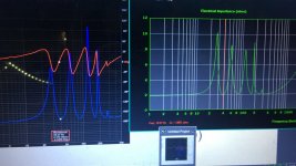
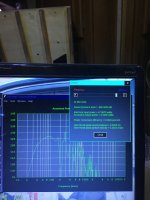
This is the response to a 1K triangle wave, just before clipping:

VirtOTL1.jpg


This is the clipping behavior:

VirtOTL2.jpg


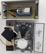
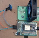
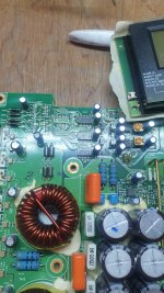
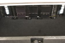
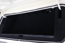
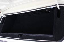
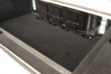
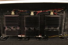
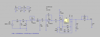
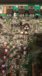
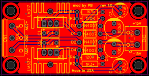
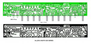
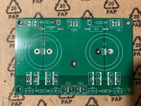
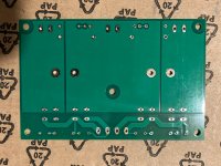
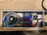
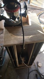
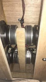
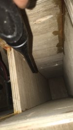
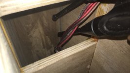
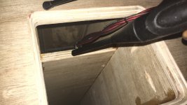
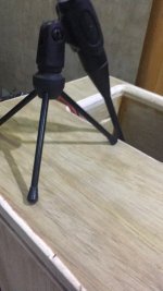
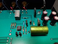
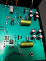
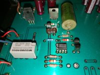
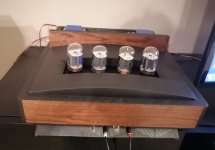
And this is the test circuit:

VirtOTL3.jpg


It is based on the same transformer and heat-sunk PCL82 as this project: https://www.diyaudio.com/community/...rging-a-e-pcl82-amplifier.351667/post-6134055

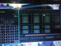
With 10K in the screen grid, the output power is 4W for 1% THD (Vs=320V, Itot=50mA).
With the auxiliary winding in the grid circuit, the output rises to 5.5W for 1% THD, and the supply current to 60mA .
I also include the .asc, but for reference only: the values have been heavily altered according to the real circuit, and they might not work well in sim
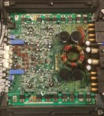
Attachments

Studer Parts....Pinch wheel/roller cover....and button covers. A longshot!!...

Hi Folks
....I know (well think I know) that the pinch wheel for the A807 is the same as that for the Revox B77....therefore available!
However....I'm also looking for the cover/shroud that goes over the wheel??
Anyone 'out there' has a spare perhaps....or know a man that does??
[IMG]


I'm also on the lookout for a RESET button cover/lens blanking piece (well 2 of those blanks are missing!!)
IMG_20220609_150227.jpg

Crossover parts need replacing?

I have large floor standing speakers that are actively biamped using an external active crossover, with the output from the crossover going to one amplifier channel for the woofers, and the output going to another amplifier channel for the mids/tweeters. The output for the mids/tweeters goes to an external passive crossover box to split the mids and highs. The speakers sound great on most recordings, with tremendous detail and transparency, but lately I’ve been noticing a “fuzziness” or “indistinctness” on loud massed strings on some recordings. I’m trying to pin down the cause of what I hear. The possibilities that come to mind are:

  • It’s in the recordings, has been there all along, and I’m just paying attention to it now for some reason. I need to pick better recordings.
  • Something in the speakers is being overdriven or has gone bad. I’m not playing things at extraordinarily loud volume, but I don’t play things softly either.

  • If the second possibility is the case, is it possible that some component(s) in the passive crossovers needs replacing? They’re about 22 years old. I’ve never looked inside the boxes, so I don’t know the details of the construction.

Recommendations for power amps for Acoustat 1+1

I just got my brother a pair of Acoustat 1+1 in good condition. He has an ARC Sp11 and the large EMT turntable with original cartrage. The main question to this forum is what the power amp should be? Also, any other factors that are specifically important for these speakers? For example, would perhaps a step-up transformer be better than the phono stage of the SP11, what kind of.speaker cables? By brother listens to classical, jazz, and vocal, but not pop. He has a large duplex height wooden living room, does not care for excessive volume, but natural musicality and good imaging.

Thank you!

FW F4 done but...

After quite a long time the F4 got to and end and made it to my place, very nice build off of the guy who made it for me, I will some day take pics to show the dual mono arrangement with custom filtering, very well done but...

But it doesn't do it with my JBL L220 (90dbW/m) and Audio Research SP9, with my other power amp (dual KT88) the volume knob to hour 11 at the most, now all the way to the max and still not enough pressure, I will try to move the line input to another source on the pre to see if there is a little more gain but to this moment in time I am quite disappointed.

I know the AR SP9 swings about 20/21db on the outputs, I am collecting stuff to build a BA-3 preamp with 30V to achieve a little more gain than the SP9, I left the thread a while ago as I am in my very busy season so I can't recall correct gain figures but would that be enough to not make me blame myself for my F4 decision vs the KT88?

Grazie

Service manuals for CDM-9pro based machines

I m trying to align an older CD player with a CDM-9pro pickup after replacement. The pickup board of the particular machine I'm working on has no focus or tracking adjustments which means they are automatic but it does have a laser adjustment on the pickup itself. I've searched the internet for a service manual from the folowing models below which have CDM-9pro pickups hoping to find adjustment procedure. If anyone has any of the manuals please share the CDM-9pro laser adjustment procedure. I've measured laser power & got .115 mw using a laser power meter,for reference using the same meter I got .12mw from a properly aligned CDM1MKII & .15mw from a CDM3. Thanks in advance.

Philips CD23
Philips CD23limited
Philips CD23D
Rotel RCD990
PS Audio Lambda II
Audiolab 800CDM
Burmeister 979
EMT 982 Professional
Jardis JD-1
NAIM Audio CD1
Marantz CD23

Swiss Physics model 5 preamp MM phono input

Hi All,
Recently I bought a 2nd hand Swiss Physics model 5 pre-amp and find there is problem with the mm phono input.
The Swiss Physics has two phono input (MC & MM). I have tried 2 MM heads (AT140ML & Shure V15VxMR), 2 TT (Thorens TD321/SME3009R & Rega Planar 3) with Swiss Physics MM, all the combination sound poor, blur (not clear).

I try a AT-F3II mc head/Thorens TD321 with Swiss Physics mc input, it sounds bright and great. Also try AT-F3II mc head with AT660T/OCC (Transformer for MC phono cartridge) connect to Swiss Physics MM input, select AT660T to 3ohm, it also sounds bright and great.

Any idea what is going wrong with the Shure (& A140ML)/Swiss Pyhsics MM combination?
I don't have the manual for Swiss Physics and don't know if the previous owner has modified anything. Thanks in advance.

Specification of the 3 pickup:

AT140ML mm
Output voltage 5.0mV
Coil impedance 3.2kohm (1 kHz)
DC resistance 790 ohm
Coil inductance 490 mH
Load resistance 47 kohm
Load capacitance 100 ~ 200 pF

Shure V15VxMR mm
Output voltage 3 mV
DC resistance 1000 ohm
Coil inductance 425 mH
Load resistance 47 kohm
Load Capacitance 250 pF

AT-F3II mc
Output voltage 0.35mV
Coil impedance 12 ohm (1 kHz)
DC resistance 12 ohm
Coil inductance 50 uH
Load resistance 100 ohm, 200 ohm

CDM9 Pro

Hi, everybody!
I`m new here and need some help for troubleshooting. Have a Micromega Trio transport with CDM9 Pro. Was sent for upgrade and came home with broken ribbon/flex cables for both laser and motor. This happend during transport. Packing can never be good enough.....😱

I understood early on that getting spares for CDM9 Pro was difficult, expect for laser that can be swapped for the regular CDM9. After some exctensive searching on the web I got in contact with a german company selling new ones. Got hold of one within a week. Great🙂

Well great until assembly was ready and this happend: When I put powercord in the player the motor starts spinning at once and won`t stop. The on/off button does not react. When I put laser cable in/out of PCB contact the speed increase/decrease but does not stop anyway. After some fumbling around it suddenly operated 100% for 15 minutes and then failed again. I don`t know how these mechanisms really work and what "triggers" this behavior?
Lasers actually come in 6 different types marked 1-6. There are industrial type, CD types, Cd rom. CDM9 have nr.2 while original Pro has 4. Well mine is 6 which is the first I have seen..........

Any suggestions were to look. Laser? motor? power supply? adjustments?

Tips is most welcome!🙂

Push-pull 807 amplifier without global NFB

Let me share my current project, a push-pull amplifier with 807 output tubes. Since this is a rebuilt of my old construction, I wanted to reuse some parts, especially the chassis, power transformer and output transformer, at least the iron. I set some design rules for myself:

B+ should stay below 400V​
There will be no global negative feedback​
Local feedback in each stage​
The output tubes will be driven from cathode followers​
Perfectly symmetrical driving of the output tubes​
Possibility to connect in ultralinear, triode or pentode operation​
AB1 class of operation​
Around 10W or more output power​
Below 1% THD at full output if possible​
I know the 807 shines at 600...800V anode voltage, but I wanted to build as simple as possible. Also I don't feel comfortable with that voltage level.
The simulation is promising, see attached circuit diagram. I will add some measuring data later.
------------------------------------------------------------------------------------------
Edit: after simulation and measuring the actual circuit it turned out that global negative feedback is unavoidable. It is because the amplifier in open loop has too high output impedance (and relatively high THD). On the other hand, with GNFB one has to take care of phase margin, so that the amplifier should be stable under complex load. I tuned it by watching the step response and experimenting with various compensation.

Attachments

  • PP_no_GNFB.jpg
    PP_no_GNFB.jpg
    50 KB · Views: 1,224

What are the reasons to not be considering building 3-way active speakers over purchasing 2-3x priced 3-way Passive speakers

What are the reasons to not be considering building 3-way active speakers over purchasing 2-3x priced 3-way Passive speakers. Is there a specific and solid reason that I should not be considering to do that. I can possibly get good System for Half the price or even less. And specially for Home theater system that can be a huge cut off budget wise. With decent Drivers which have good reviews will I not be able to manage to build a better active speaker than what Passive models have to offer even at much higher price range.

Total noob

So I'm really trying to get into the DIY speaker build/design area and I'm needing some advice. I'm still learning a lot of the lango used and don't understand some of it but I'm trying so be patient please. I have some basic questions up front to ask so please give any advice and recommendations possible. I was thinking of building some enclosures that would use a full range driver (so i don't have to try to use a crossover this time around) and a horned enclosure. I have a broad range when it comes to taste of music and enjoy a good bass line so i would like one that gives a good low end. So now the questions.
1. Best recommendations for driver that produces a good low end while maintaining clarity. Please keep it moderately priced, say around 100 or lower for price.
2. Best enclosure plans for these drivers to take full advantage of their low/mid/highs.
I realize that this is a broad range to get into and I cant give a more specific request but like I said I'm really just getting started.
Thanks again for all the advice y,all can give and ill try to answer any questions you have but please keep them simple for me as I am still learning the terms and language of audio/acoustics.
I'm excited to get going in this field and hope to become a regular on here.
thanks again MIKE

Ceramic aluminum nitride TO220 insulators. thermal grease?

First time using these, because they are supposed to transfer vastly more heat to the heatsink than mica or silicon insulators. The question I have is... Do I still use a quality thermal grease like DuPont with these? Or do you mount these insulators dry? They are a porous crystalline solid dielectric but with very high heat transfer, so wondering if the grease helps or hurts. Debating what to do, not much on Google about which way to go.

https://www.aliexpress.com/item/1005001350971494.html?spm=a2g0o.9042311.0.0.dcd44c4dEiogOD

Hello from germany

Hi all this is marcus.
I'm from germany and kind of an audiophile and into DIY Hifi stuff for a few years now.
Mainly speaker building and programming linux stuff for smart home integration of my multiroom system and my miniDSP based Mainsystem.

I came accross this forum because of a small DAC Streamer project I started for fun.

looking forward to some fun DIY time :-D

greetz
marcus

I/V and analog output stage for AD1862

Hi All,

I have a DAC that based on AD1862 dac chip, currently it uses opamps (1 for each channel) for I\V and LPF in it's output.
I'm looking to buy a kit (assembled or not) to replace the opamps, after a long search in this forum and others I couldn't find this kind of "ready made" kit.
I've seen all the I\V stage schematics in this forum but I have a very limited access to components in my area of living so building one from scratch is almost impossible for me.
I'll appreciate your help finding this kind of a kit to buy online.

Cheers,
Guy

DIY Other Related

Music enjoyment requires a comfortable environment. For example, room temperature needs to vary less than 1 degreeC. I have an ancillary project for that.

My condo unit has an integrated "Fan Coil" system for heating and cooling. This system is enclosed floor to ceiling in drywall. The thermostat is obsolete since it is switching 120vac while most thermostats now are low voltage for home owner installation. I attach a photo.

The thermostat has a corrugated disc filled with nitrogen. It expands as temperature rises, pushes a pin that clicks a switch behind the drywall that activates a relay to turn on the fan. It is the cheapest thing that could possibly work. But there is no setting that is consistently comfortable. It tends to turn on late and stay on too long. I call it shifting hysteresis.

The image includes a HS-422 servo and a generic ESP32. The ESP32 receives a on-off every second on it's PCB antenna. It presses or releases the disk. It is using WiFi hardware and ESPNOW protocol which does not compromise the WiFI credentials.

The remote in the second image has another ESP32 and a MCP9808 temperature sensor connected by I2C. Temperature is always within 25C +- 0.4 .. There is no adjustment knob or display since the settings rarely need to change.

That's it .. it works very well.

Attachments

  • Therm1.jpg
    Therm1.jpg
    77.7 KB · Views: 117
  • Therm2.jpg
    Therm2.jpg
    37.7 KB · Views: 109
  • Like
Reactions: system7 and AllenB

Building a DAB radio

I'm sorry to start with this, but I know nothing about radios, so please be gentle! However, I want to build my own DAB radio, and the fascia has to be no more than 110mm in diameter (round fascia). Is there a place online for me to visit to purchase everything required? Obviously, I'm looking for a 'module' that's already complete, and can be adapted to fit in the 110mm aperture - adding speakers. Many thanks in advance for any replies.

What is the technical reason as to why coax is the correct choice for unbalanced interconnects?

Hi All,

I've been reading through a number of threads regarding cable choice for unbalanced analogue interconnects. I have found it stated that the correct choice of cable for this purpose is coax and not shielded twisted pair (which would be the correct choice, according to the threads, for balanced interconnects). What I have been unable to find in the threads or elsewhere is the technical reason as to why. The tone of the threads leads me to think that using STP in an unbalanced interconnect would be detrimental to the signal. However, other threads on related topics such as wiring a phono pre-amp inside its case, led me to think that STP is ideal i.e. there should be a signal wire, a return wire and, if necessary, a shield tied back to signal ground at one end only (thus a shield is left to shield and not carry signal). This initially led me to think that STP would be a good idea for unbalanced interconnects but after reading through the interconnect specific threads I am now not sure. Any assistance in helping me understand why coax is the correct choice for unbalanced interconnects is greatly appreciated.

Many thanks to all.

Rpi Moode audio DSP amp integration

I've recently started dabbling in the world of DSP with one of the sure wondom 4*100w dsp amps. Currently my source is RPi running moode audio into a khadas tone board DAC via USB. Analog out goes into the Wondom board via the 3.5mm jack.

The wondom board reportedly accepts an i2s input, so I was wondering if there is way to stay in the digital domain and bypass/eliminate the Khadas DAC conversion step.

I assume I might need a USB to i2s converter? Or is there another way?

Alpine MRD-M1005 helps excessive current draw

Hello friends! Once again I try to repair an alpine brand amplifier and with different symptoms than the other 2 that I had to work on... this time there is audio, only the current consumption is excessive, it reaches 2.5 amps without audio and it starts to heat up 2 transistors Q306 and Q901.... remove all the output fets as well as ic 303, 304, 305, 307 and 308, to rule out that these were shorted and forced any of the Q306 and Q901 but no improvements, note that the voltages in Q306 are from B: 0v C: -21.4v and E: -21.9v those should not be the voltages according to the service manual but I cannot find which components are lowering it and forcing these transistors in advance I thank you for your help greetings

Attachments

  • 20220606_164216.jpg
    20220606_164216.jpg
    564.8 KB · Views: 450
  • 20220606_145657.jpg
    20220606_145657.jpg
    434.9 KB · Views: 256

For Sale Adjustable wire-wound resistors, 25k, 25 watts.

These are nice, never—used, old stock WW resistors. They have printed on them: TRW 7919, Type 2 DA, 25K 10%, 25W.

PM me if you need some. I have a whole box full. Make me an offer, around $1 each. Shipping from 61821 is on you. USPS money order, please.

Attachments

  • 29C7F574-BBF5-4116-BCC4-19B32075C523.jpeg
    29C7F574-BBF5-4116-BCC4-19B32075C523.jpeg
    472.5 KB · Views: 96
  • 7219EC65-05C0-4739-A16F-4DB9BAC892BB.jpeg
    7219EC65-05C0-4739-A16F-4DB9BAC892BB.jpeg
    468.3 KB · Views: 102
  • 9CD22C70-DBCD-4AFA-8498-8AEDB0FEE0DD.jpeg
    9CD22C70-DBCD-4AFA-8498-8AEDB0FEE0DD.jpeg
    806.3 KB · Views: 123

  • Article Article
TDA1387 and TDA1545A

When I first got into multibit DACs my 'starter' chip was TDA1543 as there was so much choice of boards with various implementations in single and paralleled form. As time went on I experimented with replacing these rather power hungry bipolar technology chips with CMOS DACs which took way less power. The most attractive one from the point of view of power consumption was TDA1545A, this runs at a mere 15mW, though if you want 2mA output swing (which I normally did) the power rises to ~30mW. Running in 'enriched mode' is set out in the datasheet but I would often find some 'fuzziness' of sound which I couldn't track down and so in the end I gave up with this chip and moved on to TDA1387. This can't be current enriched - I tried once and blew up a few but has a considerable advantage over TDA1545A in that its output compliance range includes 0V. This feature makes it really easy to implement passive I/V with a single resistor and no additional biassing components.

Nowadays I'm chasing an ever lower noise floor in my DACs and was curious to give TDA1545A another whirl to see if I could track down the reason for the fuzziness. I arranged 6 of them in parallel in my current development 'Abbado' DAC and found even worse sound than mere fuzziness, it was so crackly as to be unlistenable. After much head-scratching and experimentation with external circuit parameters I eventually discovered that the datasheet specification of output compliance voltage doesn't apply to the DAC operating in 'enriched' mode. Here's what the DS has to say :

1647420228147.jpeg

The lowest voltage tolerated by the DAC's analog outputs is 2V and I was running very close to that, given that I was feeding an NMOS source from the output and wanted the maximum possible output swing. But if you run the DAC at 2mA this spec isn't valid any longer, it turns out 3V will do the trick but 2.5V definitely doesn't. The DS application circuit using opamp I/V has 3.3V. There isn't any mention that the 2V figure should be increased if you up the DAC's output current. So all those years ago when I encountered fuzzy sound the explanation was that I was running at too low an output voltage.

The internal topology of TDA1545A is rather different from than within the TDA1387. On the TDA1545A the DAC element is arranged to sink current from the output to GND and there's an internal biasing current source whose magnitude is determined by the input current to pin7. This current source is connected between the output and pin5 (VDD). So this CCS sets the top limit of the output compliance, at VDD-1 volts. The DAC sinks 0.5mA at digital zero leaving 214uA from the CCS to exit the output pin. At positive maximum the output will be +714uA and at negative maximum the output will sink 286uA (714-1000uA). Thus TDA1545A's output is asymmetrical bipolar, with an offset current in the sourcing direction. While I've not checked it, it looks as though the supply current to the chip will be constant with digital code, in contrast to the TDA1387. This latter part has the DAC element between VDD and the output pin hence more output current requires more supply current. There is a low-valued CCS in parallel with the DAC so full scale negative still outputs a current, about 80uA.

The SQ of 'Abbado' but running with a current swing of 12mA sounds slightly richer and warmer than the original Abbado utilising 6mA from 6 TDA1387s. But that design isn't production ready yet as TDA1545A @2mA takes more supply current than TDA1387 and doesn't have I2S input, I need to come up with a way to convert I2S to right-justified. Perhaps that's a job for a CPU.

1647422126991.png

1647422160437.png
Here we see how the SNR increases by 3dB from doubling the DAC's output current.
Projects by fanatics, for fanatics
Get answers and advice for everyone wanting to learn the art of audio.
Join the Community
507,666
Members
7,883,363
Messages

Filter

Forum Statistics

Threads
405,990
Messages
7,883,363
Members
507,666
Latest member
Fpa420