Hey guys
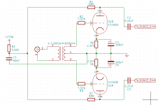
I've acquired a diy push pull tube amp based on ecc83s and 6l6gc. Was initially made to take in balanced signal, shorted it to be able to use unbalanced. Been studying it for a while as I do not come from the electronic engineering background.
I want to build some sort of a volume control for this amp.
One of the options is to go with a passive pre amp but for that I need to understand how to match the impedance in order no to mess up with the high frequencies.
There is one interesting design feature of this amp that it does not have a grid leak resistor on the gain stage, just a grid stopper. Now naturally the input impedance is approximated by the grid leak value, but how do you calculate it when there is no grid leak resistor?
I am afraid that without having a grid leak, anything I will put on the grid will add up to grid stopper resistance, right? Does this mean that passive pre-amp is not a viable option and I should build a buffered one? Or does that mean that only a small value pot would work right, such as 10k
I've attached the gain stage circuit for clarity. Please let me know if there are any issues with the drawing. This was the very first circuit I've drawn in my life.
Attachments
Last edited:
The secondary winding of the input transformer provides grid leak function, at a very low dc resistance but high ac impedance (which is a good thing).
Use of a passive volume control will be dependent on the transformer parameters.
Use of a passive volume control will be dependent on the transformer parameters.
The secondary winding of the input transformer provides grid leak function, at a very low dc resistance but high ac impedance (which is a good thing).
Use of a passive volume control will be dependent on the transformer parameters.
The transformer is a Tamura TK 10 with 600 ohm on both windings and the turns ratio is 1:1
Could you please be a bit more specific on how does the transformer affect the pot value choice? Does that mean that I should match the pot to 600 ohm winding resistance?
Using sources or loads with volume-dependent impedances with the transformers is bad idea - the frequency responce will vary greatly with the pot wiper position. Even more, 600 Ohm transformers have quite low inductance, so even the 10k will be too high value for the pot.
The healthiest way to add volume control to this amp is to use quad pot (two sections per channel, one section for each secondary half) of the convenient value (10k-100k) on the secondary side of the input transformer. You'll also have to add the "real" grid leak resistors (5x-10x of the pot value) from the pot wiper/grid stopper connection to the ground.
The healthiest way to add volume control to this amp is to use quad pot (two sections per channel, one section for each secondary half) of the convenient value (10k-100k) on the secondary side of the input transformer. You'll also have to add the "real" grid leak resistors (5x-10x of the pot value) from the pot wiper/grid stopper connection to the ground.
Using sources or loads with volume-dependent impedances with the transformers is bad idea - the frequency responce will vary greatly with the pot wiper position. Even more, 600 Ohm transformers have quite low inductance, so even the 10k will be too high value for the pot.
The healthiest way to add volume control to this amp is to use quad pot (two sections per channel, one section for each secondary half) of the convenient value (10k-100k) on the secondary side of the input transformer. You'll also have to add the "real" grid leak resistors (5x-10x of the pot value) from the pot wiper/grid stopper connection to the ground.
Wouldn't a buffer address the problem of varying impedance depending on the pot position? Asking this as I am not sure if buffer placed after a pot would allow to have a constant output impedance
Last edited:
It would. But the quad pot is cheaper 🙂Wouldn't a buffer address the problem of varying impedance depending on the pot position?
It would. But the quad pot is cheaper 🙂
Point is that a relatively good 4 gauge pot is rather expensive and having two separate ones I believe would be pain in the ... to match right/left channels. In addition to that, from what I've read, I believe that wire pots are no good when it comes to attenuating the level for balanced/two separate halves due to inaccuracies per gauge which means that I should probably get myself a stepped attenuator.
With all this in mind and the fact that I already have somewhere TKD 2cp-2511 100k stereo pot laying around, wouldn't the buffered pre-amp in the end be a cheaper option? Talking about DIY of course.
If that's the case, do you have any personal schematic recommendations?
Bourns PTD904 is quite decent and available under $3 at Mouser.Point is that a relatively good 4 gauge pot is rather expensive
That issue is heavily overrated IMO. There are lots of sources of possible imbalance in the circuit (tubes, passive components, sometimes even the input transformer itself), but everybody tends to blame just the pot.In addition to that, from what I've read, I believe that wire pots are no good when it comes to attenuating the level for balanced/two separate halves due to inaccuracies per gauge
Anything that suits your taste and budget and has low enough output impedance (preferrably 100 Ohm and below).wouldn't the buffered pre-amp in the end be a cheaper option? Talking about DIY of course.
If that's the case, do you have any personal schematic recommendations?
Bourns PTD904 is quite decent and available under $3 at Mouser.
That issue is heavily overrated IMO. There are lots of sources of possible imbalance in the circuit (tubes, passive components, sometimes even the input transformer itself), but everybody tends to blame just the pot.
Anything that suits your taste and budget and has low enough output impedance (preferrably 100 Ohm and below).
Alright, due to the great shortage of parts I guess I'll have to go with the quad gang pot for now. Not every transistor can be acquired nowadays for the Mezmerize DCB1
Do you suggest that the grid leak resistor is mandatory? If yes, what are the potential side effects of adding it, what would be the signs of an inappropriate resistor value?
Even If I decide to go the buffer/no gain pre-amp route, the grid leak should stay there, right?
Let's say I solder in a 1M resistor, the input impedance would be close to 1M? Then should I lower the grid stopper value to accommodate the 10k or so pot ? I suppose the pot should go after the secondary winding.
If the input transformer is rated for 600 ohms but not loaded with 600 ohms, its frequency response might be quite peaky and not what you'd expect.
If the input transformer is rated for 600 ohms but not loaded with 600 ohms, its frequency response might be quite peaky and not what you'd expect.
Are you suggesting that coupling with a cap is a better choice than with a transformer?
Raising this thread as I am dealing with question again.
So if there's an impedance matching transformer rated at 600 ohms, does that mean that the actual impedance the previous stage - source - sees is 600 ohm ? If so, the buffer's output impedance is rated at ~260 ohms, I believe the ratio is a bit small. Anyway, would there be a way to increase the input impedance (l-pad or something) or the only solution is to remove the transformer from the path and introduce a coupling cap?
So if there's an impedance matching transformer rated at 600 ohms, does that mean that the actual impedance the previous stage - source - sees is 600 ohm ? If so, the buffer's output impedance is rated at ~260 ohms, I believe the ratio is a bit small. Anyway, would there be a way to increase the input impedance (l-pad or something) or the only solution is to remove the transformer from the path and introduce a coupling cap?
If you have a 600R:10K transformer, AND you load it with a 10K load, the primary will reflect 600R. If you load the same transformer with only 5k, the primary will only reflect 300R.
Transformers do what they say on the tin. The transform voltages, currents and inpedances. A transformer does not have an intrinsic impedance but, due to engineering limits and audio transformer will be designed to work best over the entire audio range at a specific impedance. This implies you need to take this impedance ito account in your design. In this case you have a 600:600 transformer. So. its performance will be best when loaded with 600 ohms. So you need to work out what value resistor to put in parallel with the quad pot such that the secondary load is 600 ohms. So probably a 620 ohm resistor will do the job.
The other thing to remember is that this impedance is reflected to the primary so and source driving the transformer input will see a load of 600 ohms. Few if any hi-fi products will drive this load. One solution to this problem is to replace the transformer with a 10K:10K one. YOu can then load the secondary with a 10K pot and this will be reflected through to the primary so the input impedance will also be 10K. Something like the Sowter 3575 would do the job.
Cheers
Ian

I apologize in advance if the text bellow makes no sense.Transformers do what they say on the tin. The transform voltages, currents and inpedances. A transformer does not have an intrinsic impedance but, due to engineering limits and audio transformer will be designed to work best over the entire audio range at a specific impedance. This implies you need to take this impedance ito account in your design. In this case you have a 600:600 transformer. So. its performance will be best when loaded with 600 ohms. So you need to work out what value resistor to put in parallel with the quad pot such that the secondary load is 600 ohms. So probably a 620 ohm resistor will do the job.
The other thing to remember is that this impedance is reflected to the primary so and source driving the transformer input will see a load of 600 ohms. Few if any hi-fi products will drive this load. One solution to this problem is to replace the transformer with a 10K:10K one. YOu can then load the secondary with a 10K pot and this will be reflected through to the primary so the input impedance will also be 10K. Something like the Sowter 3575 would do the job.
Cheers
Ian
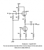
So this is the line stage circuit.
Input is unbalanced. I assume that for positive cycle, the load the transformer sees on secondaries is R2 + Resitance between grid and cathode + R5 C4 filter. Is that correct? In that case it is way above the 600ohms and this said higher impedance is reflected onto the primaries meaning, that the imepdance the source sees is higher than 600?
Or another idea. Does it mean that if that the current will flow and it will create an opposing magnetic flux that will oppose the one originating from primaries. It's just that the load is hgh, current is small, the flux will also be weak, thus the source will see impedance not 600, but rather close to 600...?
Last edited:
Basically yes but in practice no. The impedance between grid and cathode is extremely high - at least many Megohms in parallel with a small stray capacitance. In theory this very high impedance is reflected to the primary so as you say the source sees an impedance much higher than 600. In practice this is not the case because this transformer is designed to work at 600 ohms. In a real transformer, the inductance of the winding is in parallel with the reflected impedance. What that means is that the inductance of its windings should be designed such that above 20Hz or so it will be greater than 600 ohms. This inductance is what limits the low frequency response of the transformer. WIth such I high secondary load, the reflected impedance is going to be almost entirely due to the transformer inductance and so will rise linearly with frequency. Not what you want. And unfortunately, a lot of lower cost transformer manufacturers assume their 600:600 transformer will actually be driven by a much lower source impedance like 50 ohms or so. This means they can make the winding inductance a lot lower but still call it a 600:transformer which means it will be smaller and cheaper because you need less turns of copper and of course almost all manufacturers fail to publish winding inductance.
Bottom line is a 600:600 transformer needs to be loaded with 600 ohms to work properly which in turn means the reflected input impedance will be 600 ohms. If you want a 10K input impedance you need a 10K:10K transformer.
Cheers
Ian
Bottom line is a 600:600 transformer needs to be loaded with 600 ohms to work properly which in turn means the reflected input impedance will be 600 ohms. If you want a 10K input impedance you need a 10K:10K transformer.
Cheers
Ian
Alright, to summarize. In this case the input impedance is capped at 600 ohms. To achieve 10k input impedance and to maintain a healthy impedance ratio between the preamp (~250R) output impedance and amp's input inpedance I need a 10k primaries transformer which would be loaded with a load equal or close to the secondaries impedance.If the load is smaller, the input impedance is less than the primaries nominal. If the load is greater than the secondaries nominal,, low-pass filtering/any other unwanted sound distortion occurs.Bottom line is a 600:600 transformer needs to be loaded with 600 ohms to work properly which in turn means the reflected input impedance will be 600 ohms. If you want a 10K input impedance you need a 10K:10K transformer.
So now I have two problems 😀 !
1. Buy new transformers
2. Adapt the existing circuit to match the secondaries nominal and/or choose an appropriate transformer for this case.
If I have understood you correctly, it is pretty tricky to calculate the load the transformer's secondaries see ?
The impedance between grid and cathode is extremely high - at least many Megohms in parallel with a small stray capacitance. In theory this very high impedance is reflected to the primary so as you say the source sees an impedance much higher than 600.
To what extent this problem can be reduced? Is it enough just to match the gird stopper resistor?
That isn't really correct. Grid stops, like R2, connect to an essentially open circuit, the grid, in series. So they plus the grid are essentially an open circuit. By that same reasoning, the cathode bias components (also in series with the valve's input impedance) are in series with that essentially open circuit, so also don't contribute. Does that make sense?I assume that for positive cycle, the load the transformer sees on secondaries is R2 + Resitance between grid and cathode + R5 C4 filter. Is that correct?
To load the currently unloaded transformer, you would add a 600 Ohm load from pin5 to pin3. Pin1 to pin2 would now look like 600 Ohms to your source, so you have some difficult choices to make.
All good fortune,
Chris
Hmm, could you elaborate on what do you mean by difficult choices, as for me it seems that I need new transformers and load them with good quality resistors..? Are there any potential unwanted side effects? Of course Im having in mind new 10k ones.That isn't really correct. Grid stops, like R2, connect to an essentially open circuit, the grid, in series. So they plus the grid are essentially an open circuit. By that same reasoning, the cathode bias components (also in series with the valve's input impedance) are in series with that essentially open circuit, so also don't contribute. Does that make sense?
To load the currently unloaded transformer, you would add a 600 Ohm load from pin5 to pin3. Pin1 to pin2 would now look like 600 Ohms to your source, so you have some difficult choices to make.
All good fortune,
Chris
- Home
- Amplifiers
- Tubes / Valves
- ECC83S/12AX7 Omitting grid leak, input impedance and preamps