I decided to clean my space from some Sansui parts what I collect durring many last years... Some of them are used, the most of them are NOS, never connected to some power supply.
So, this is the list, first never used NOS boards:
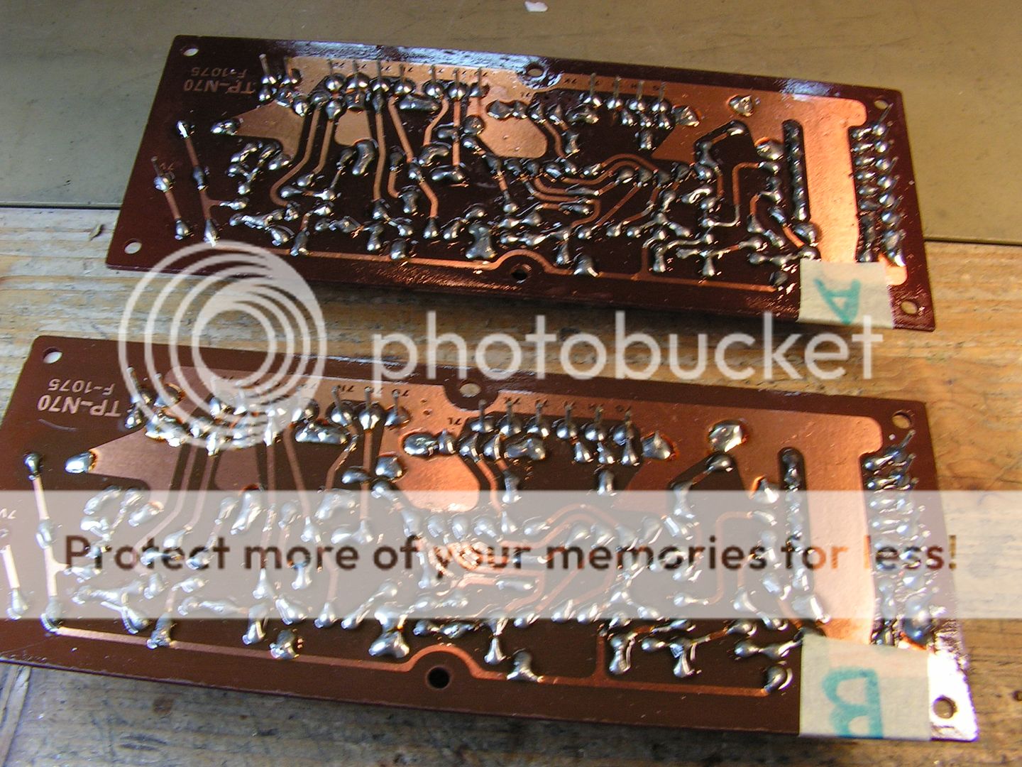
- Board F-1075 for amplifier PA-100
- Board F-1267 for amplifier AU-555
- Equalizer/Tone Board F-1303 For Amplifier AU-505
- Board F-1319 for Quad Amplifier QR-500
- Tone Control Board F-1436 for Receiver Six & Seven
- Equalizer Board F-1435 for Receiver Seven
- Tone Control Board F-1207 for AU-777A
- Board F-1378 for QS 500
- Board F-1216 for Receiver model EIGHT
- Motor for Turntable model P 50
- Board F-1371 for Receiver model QR-4500
- Board F-1328 for Quad rear amplifier model QS-1
- Board F-1357 for Quad Amplifier QS-500
- Filter Board F-1208 for Amplifier model AU-999
- Equalizer Board F-3015 for Receiver TA300 & TA500
- Board F-2701 for Receiver 6060 and 5050
- Selector-Equalizer Board F-2727 for Amplifier AU117 & AU117mkII
- Tonearm for Turntable model PD 10
- Tonearm for Turntable model P 50
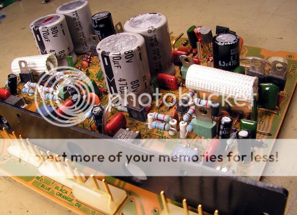
- Driver Board F-2661 For AU9900A/11000A
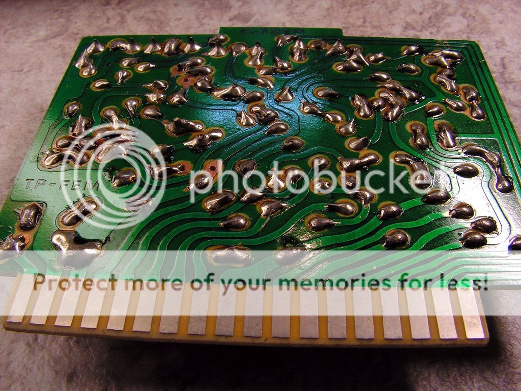
- Driver Board F-1278 For EIGHT
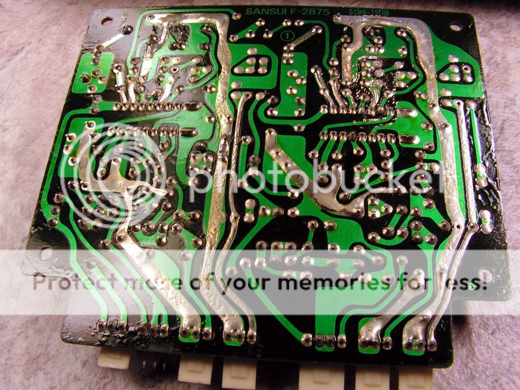
- Buffer Amp Board for TU919 F-2875
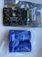
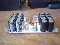
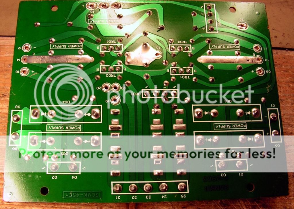
- Power Supply Board F-2963 for BA-F1
And now some used boards, but in very good condition:
- Loudness Board F-3084 for G9700
- Power Supply Board F-3070 for G9700
- RF Power Supply Board f-3071 for G 9700
- Equalizer Board F-3219 for G9700
- Audio Switch Circuit Board F-3079 for G9700
- Pre-Power Supply Board F-3073 for G9700
- Tone Control Board f-3050 with Volume Control Board
- Digitally Display F-3088 Board for G9700
- Power Indicator Board F-3082 with F-3083 and F-3077 for G9700
- LED Power Meter Board for G9700
I would update this post with new parts and I would remove sold parts.
For the prices and many pictures please ask, I can say the most parts are about from 40 to 60 US$, but some of them has higher price (like "Driver Board F-2661 For AU9900A/11000A" or "Tone Control Board f-3050 with Volume Control Board")
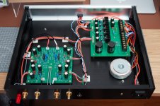
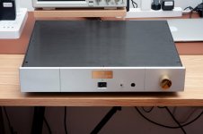
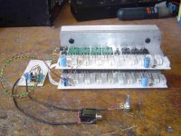
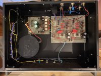
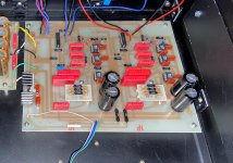
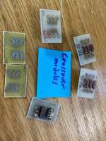
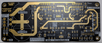
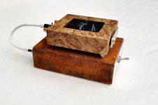
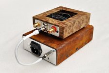
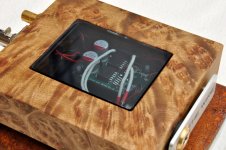
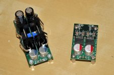
Some of pictures:
For more info, please send a PM, or better way... please send an email to
kale_021@hotmail.com


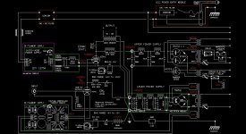
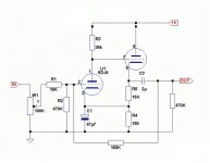
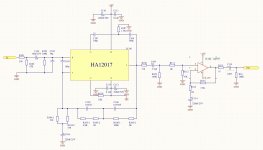
 I have a leak trouble line II FM radio. The audio signal line is mono channel. When I came, it was connected to DIN 3 pin. Now I want to change it to 2rca plug. Can I directly split two left and right channel lines here? The positive and negative poles are divided into two lines, which are connected to the left and right channels of the amplifier. Attach the schematic diagram of the machine. Please help me have a look. Thank you,🙂