Using the new 2012 Shigaclone to create a killer high end transport

Now that payments are being made and production is starting for the 2012 Shigaclone

http://www.diyaudio.com/forums/digi...affordable-cd-transport-shigaclone-story.html

I thought we should start a new thread with recommendations for how to turn this latest version into a giant killer of a transport. First of course, great thanks needs to go out to our friends in Poland, Peter Daniel, Tvicol, Jazz35, and anyone else I forgot to mention. None of this would have been possible without this team's collective work.

With Tibi's okay it seemed like a new thread would be a good place to start this phase of discussion for the 2012 Shiga. My proposal is that we work on creating a transport that can go up against the likes of the ML 31.5, CEC TL0, Linn CD12, Wadias etc. I know there is no one "best transport in the world", just as there is no single best of anything in high end audio, but the plan is to try and get to a level where a tweaked Shiga can stand on its own against the most highly regarded transports of the past and present.

I’m not suggesting the new Shiga won’t sound good at the start – I suspect it will sound pretty darn good. The hope is to take it to the best it can be.

I further propose the following as a baseline definition:

  • Use the 2012 Shiga design currently in production as the starting point
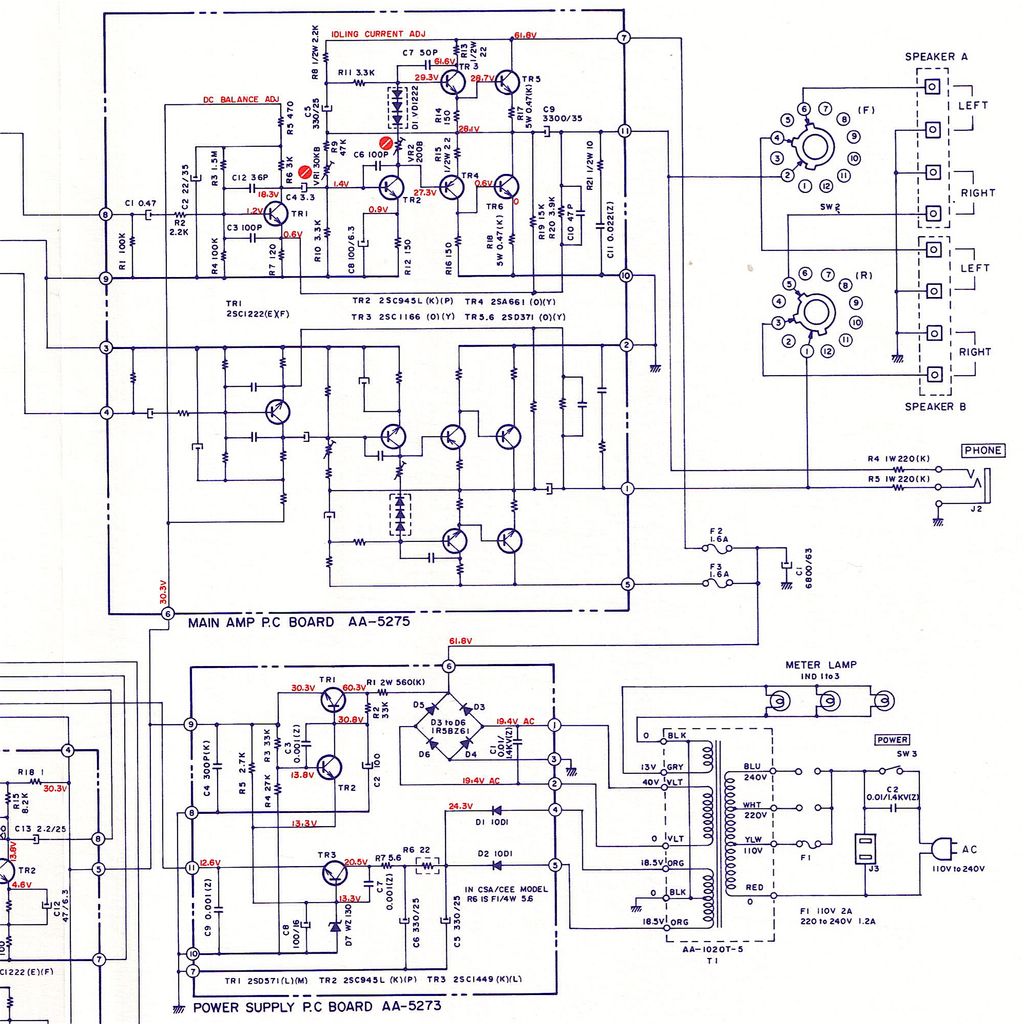
  • Post (or link) the latest production schematics, BOM, PCB drawings etc
  • Use this thread to identify from the original Shiga thread(s), and any others, the key posts made to date which discuss advancing the design. I know this sounds vague, but rather than everyone searching through 600+ pages of one thread, plus any other related threads, I'm hoping those who were part of some of those original tweak discussions can provide links here so we can have one place where this information has been filtered.
Once we start getting these units and have had a chance to understand what they can do, perhaps then we can identify the areas where tweaking may prove beneficial… areas like

  • Power supplies (parts swap, or going further like considering a Bobken)
  • Clocks (although Peter has some interesting things to say about this)
  • Output stage
  • Specific component changes
  • Chassis and mounting options
  • Ferrites and shielding
A lot of discussion has occurred in most of these areas. Many may be a good starting point for the 2012 Shigaclone. Those with test equipment who can help quantify any improvements would be a great asset. (I'm neither a complete subjectivist nor a card-carrying DBT'er. A combination of listening impressions and data would be a great thing to have.) Does this sound like a good plan?

Chinese Accuphase E405 Clone - give it a try?

Hello to everyone,
I am quite new in the field of DIY audio! Like a technical draughtsman is not an architect, I am not an engineer either. I have quite good soldering skills and I can handle with (most) technical specifications but I am far from being able to develop or improve anything by myself. But as it is, like most men I am always looking for a new project! Besides my studies (25 years ago) I earned my pocket money in a high-end studio and fell in love with an e-something (maybe E-305?) Accuphase at the time. Now I have discovered the following DIY kit on Alibaba: Accuphase E405
My search on this wonderful forum has unfortunately yielded no results, has anyone already made experience with this clone - Try it or is that a no go?

best regards
Henning

Minimum voltage for linear region of amplification

First I apologize for my ignorance on this matter and for perhaps asking a question that for this forum is obvious. I'm trying to make my first headphone amp using tubes. I have seen some circuits on the internet using tubes, 6k4, 6J9, 6N2, 6N2, 12AU7, 12AX7 etc. but all of them with supply voltage of 12 volts. In my limited experience (Ham radio) I have never used such small voltages... and according to the dynamic plate curves ( ib as a function of Eb with Eg as parameter) and my limited knowledge, with those voltage levels, the valve is very far from working in its linear zone, and consequently its distortion should be high. But supposedly these amplifiers have very low distortion, which seems contradictory to me. My question is: really with 12 volts is it possible to get a low distortion amplifier (and what is the applied concept), or in these amplifiers are the valves just "for decoration"?
Tks in advance

Analog interface to get an audio analyser from a soundcard

I was tired to solder divider diy patches every time I needed to measure power amplifiers with a soundcard, and also by investigating how to avoid groundloops and mains related interference spectral lines. So I decided to design and build a fully balanced universal analog interface that would change a soundcard to something that resembles an audio analyser like AP, or maybe rather like QA401. I started with using such thing a year and half ago and after getting good results, I decided to make a stand-alone instrument like this. The interface, called MSYS, has 2 channels, one for low level signals up to 4Vrms, second for high level signals up to 40Vrms (at least). The gain and sensitivity is controlled by DACT stepped attenuator. Block diagram is attached, circuit diagram is attached as well, and a photo of the instrument and its rear panel. The circuit uses OPA314, AD797, OPA627 and ADA4898 chips. Dynamic range is high, distortion very low and it makes a useful tool from a conventional soundcard. Balanced input is a must if we measure a power amplifier.

Attachments

  • MSYS.png
    MSYS.png
    32.8 KB · Views: 486
  • msys_sch.pdf
    msys_sch.pdf
    26.3 KB · Views: 242
  • msys_in.jpg
    msys_in.jpg
    271.9 KB · Views: 471
  • msys_rear.jpg
    msys_rear.jpg
    115 KB · Views: 484

Ribbon or planar headphones

The majority of headphones have quite simply awful high-frequency performance. However, by using either a single ribbon or a combination of ribbons, it should be possible to build a driver that works very well even to high frequencies with minimal energy storage. Also, according to another DIYaudio thread, the ribbon could reproduce an acceptable amount of bass, too - the short length would apparently keep it from "flapping" at low impedances.

Transmissionaudio.com has a picture of a prototype on their page, too.

http://www.transmissionaudio.com/ourribbons.html

The obvious problems with this setup would be weight (enormous) and impedance (tiny.) However, these would likely never leave my desk, and if I can get some metallized Kapton film, it should be possible to etch fine enough traces to get the impedance to an acceptable (1-ohm?) level.

A preamp conundrum - Amping my DIY speakers in an all digital computer based rig

Update. In light of new information about the amp being counterfeit I have removed the link. The question around the preamp conundrum is still relevant regardless, so I don’t want to just delete the entire thread.

Hey guys

I'm building out my first DIY speaker system and hoping for some advice. These will be speakers for my workstation. I will be doing crossover and DSP on my Mac, using the Motu M4 hardware interface and CamillaDSP software.

One thing I am having a bit of trouble with is amplification. Im interested in one of the Purifi 1ET400A based amps (link removed) from China. It comes in 2 versions: one without a volume pot and one with (for a small premium). The no volume pot version was tested and the results were phenomenal. As I understand it though, poorly implemented volume control could negatively affect the sound quality, and I haven't found any test results for the version with the volume pot.

The problem is that right now I don't have a preamp in the signal path. Since the system is being run on software, with volume controlled digitally. I feel it would be foolish to just hook the speakers up to a pure amp - risking hurting them (along with eardrums) should something iffy happen with software volume control.

So how likely is it that the volume pot version of these amps is going to suck?

If I was sure it would just be fine, then that's perfect, my problem is solved. But if it's actually a dicey situation, should I instead find some preamps and opt for the pot-less variant? (I don't really want to add much more to the bill)

tweeter below woofer in 2way?

—>make speakers for family and suddenly they are going on the ‘base’ of the fireplace instead of actual ‘floor’ … (Well over a foot higher than planned and putting the listening position ear heights and Tweeters at that ~mismatch?

any reason I can’t just flip this over and put the tweeter underneath the rs180 and leave everything as it is?(just need to cut a hole for them in the plywood)

Attachments

  • E5026044-D087-4CE8-A66A-35EF9F6A5237.jpeg
    E5026044-D087-4CE8-A66A-35EF9F6A5237.jpeg
    392.1 KB · Views: 129
  • 88D9E2D6-5926-47D4-A5AC-D7B1A5166726.jpeg
    88D9E2D6-5926-47D4-A5AC-D7B1A5166726.jpeg
    335.5 KB · Views: 132
  • 555724AC-EE04-47E2-8B3B-3F98D2594974.jpeg
    555724AC-EE04-47E2-8B3B-3F98D2594974.jpeg
    463.9 KB · Views: 134
  • 274B7B0A-3C76-4A0B-8896-58C1FF961F4F.jpeg
    274B7B0A-3C76-4A0B-8896-58C1FF961F4F.jpeg
    369.2 KB · Views: 128

Source or replacement for 2SA968/2SA2238 ?

Hi,

I have friends Yamaha M-4 on my desk for repair with burned driver and output transistors on one channel. Of course, all of them are now obsolete. I managed to acquire some replacements for the output transistors but have nothing for the driver pair 2SA968/2SA2238.
I have RS and Farnell distributors in a place where I live, but I didn't manage to find anything on their stock that could be useful in my case.
Found some that are sold on ebay though, but I I think there is a great chance of them being chinese fakes, so I would like to avoid those and find some source that is more reliable.

Does anyone have an idea on this ?

Attachments

Smart phones stupid people

Ive been saying this for a few years now. Decided to do a search on my smart phone 😉.

https://www.nbcnews.com/think/opini...-developed-countries-doesn-t-bode-ncna1008576

https://www.forbes.com/sites/forbes...e-while-iq-is-on-the-decline/?sh=6b8dc2a1b103

Anyone else noticing this? Remember when you had to memorize stuff, do simple arithmetic, read a map, estimate the time, take something apart and put it back together without a video, etc. Soon you will not have to think at all. Are we already seeing the results?

Login to view embedded media

Audiolab 8000A volume pot

Hi All

Long shot but worth a try.......
I've been fixing up a battered 8000A for a mate. Looks as though the thing was dropped at some point in the past as the volume pot shaft was sheared and the balance pot was missing altogether. I found a good 100K dual MN taper alternative balance pot that fit perfectly and stripped / refurbished the volume pot, re-pinned the shaft (fiddly job) and re-mounted - works great. Only thing is the flat lock nut is missing. I've gone through every spare pot in my stash and none of them fit. Does anyone happen to know what size/thread it is before I go buying replacements? I could be that the threads are goosed and nothing will go on. Other than that, after 2 power transistors, 2 drivers, 1 x DC servo IC, and a heap of caps and resistors, she's up and running and sounding a million bucks.

Perfect house wiring, avoiding ground loops

Hello,

I was wondering what would be the best way to wire a house to avoid ground loops.
I always got a ground loop over my balanced speaker cables.
Earth >Power Calbe> PC >HDMI> TV >HDMI> AV-Reciever >XLR> Amplifier >Power Cable> Earth
I just added a capcitor to the ground of my PC to mostly get rid of the noise but not 100%.
Or maybe decouple the amplifiers ground somehow?

Now I am thinking of rewiring my house what would be the best way to avoid this.
Seperate Ground connection for the amplifiers?

Also I was wondering, should I use the same phase for all amplifiers or is it better to use different phases?

Left channel lower volume than right

Greetings audiofolk,

I have 2 woofers. The left sounds "weaker" than the right one. Lower volume, less vivid. No crossover. Exact same woofers, brand new.

I have checked everything from internal wiring (cabinet), external wiring (audio cables), the DAC, the AMP and all the cables in between. I switched the speaker from left to right, the right speaker sounds weaker. The "weaker" woofer needs 50% more volume to stay at the same level as the good one.

So... is it the woofer/driver itself that's messed up or am I missing something?

UPDATE
AMP:
Denon AVR-4306
WOOFER:
SB15NAC30-4 (4 ohm, I checked both with a multimeter).
No crossover, no schematic.

Thorens TD125 Motor, speed controller and power supply replacement

Hello All,

I am in need of a new replacement motor and speed controller to replace the stock motor/spc on a vintage Thorens TD125. Premotec and Maxon were both motors I have heard good things about but I have no idea which model would be most suitable and how to go about purchasing/building a speed controller and power supply. I am not interested in the Origin Live motor option as I feel there may be a better solution through purchasing separate high quality parts directly from the mfg. I do not wish to simply replace the stock TD125 motor with another vintage unit as I feel the table is worthy of a much higher quality motor. Ideally, the motor would rest in the same location as the original one within the subchassis with the belt riding on the outside of the inner sub platter. I was not sure if this also played a factor when trying to find a suitable motor but thought I would mention it anyway. My thoughts were the power supply and speed controller would be outboard placement wise, so would not have to worry about fitting inside the chassis or plinth frame.

It would be ideal not to have to mess with the original power supply or internal electrolytic caps, ect. I would much rather go new all the way. 🙂

Thanks,
Chris

Attachments

  • IMG_3753.JPG
    IMG_3753.JPG
    742.2 KB · Views: 1,141
  • IMG_3766.JPG
    IMG_3766.JPG
    382.9 KB · Views: 693
  • front_top_and_base.jpg
    front_top_and_base.jpg
    66.8 KB · Views: 670
  • base_plate.jpg
    base_plate.jpg
    97.2 KB · Views: 614
  • view hz.jpg
    view hz.jpg
    58.5 KB · Views: 684

CE directives for passive speakers.

A friend who runs an independent gift shop in my town has shown some interest in selling some speakers I've made as a hobby. The first thing I thought was I wouldn't sell enough to justify the costs for lab testing for EC compliance so it is a non-starter. I've been googling but can not find an answer to what directive passive speakers fall under if any. Does anyone have any information on this?

Akai AA-1020 burning resistor woe!

Hi folks!

Hoping somebody can help me to fix up my Akai AA-1020 which has been (hopefully temporarily) put out of action due to my own stupidity!

The amp had been recapped recently, adjusted, and was working beautifully. Sounded lovely. The only problem was the old headphone socket was cracked and resulted in intermittent connection with the jack inserted. Fortunately I sourced another that was an extremely close match. Did a test fit of the new socket to make sure… and forgot I'd left it there... loose! Yep (slaps forehead!).

Had just turned off the power (thankfully, or it might have been worse) after a listening session, and the socket decided to fall into the internals at that point, creating a spark and there was a loud pop. As I said the power was off, so it was either residual charge left in the reservoir cap, or from touching the live terminals of the on/off switch (probably the most likely). Obviously there must have been some short. The spark was large enough to burn off a corner of one of the solder tags on the new headphone socket as it fell to the chassis base!

Whenever the amp is turned on now, R16b (150R) starts smoking almost immediately. Replaced it with a new one and the same result, so obviously I've really screwed something up. This is alas out of my league really, so was hoping somebody might be able to look at the circuit diagram's below, and the PCB layout (smoking resistor circled in green) and spot a potential component to check and change. I'm hoping the transistors haven't blown from that short, but sod's law being what it is I'm guessing that's what's happened.

I can’t take any voltage readings on the amp board at the moment as that resistor starts heating up immediately. Have checked for any obvious burn marks on all PCBs (there aren’t) and there’s no sign of any blown components, at least not visually.

Main PSU and Amp PCB circuit (rest of the circuit not shown is for tone control and RIAA boards):

Audio%20board%20and%20PSU.jpg


Amplifier Board:

Akai%20AA-1020%20PCB_2.jpg


What it looks like for real:

Photo%2027-02-2016%2021%2054%2010.jpg


Where to start?

Any help would be very gratefully received 🙂

Thanks.

- John

Going Where Angels Fear to Tread, We Propose Two Additions to the Thiele-Small "Canon" of Driver Parameters

"B x l," also known as "Force Factor," is one of the canonical Thiele-Small Parameters.

As explained in the linked-to paper, Jim Tuomy and I believed that a new Parameter, complementary to and analogous to Force Factor, would be helpful. We call that new Parameter "Load Factor."

Then, when one expresses the relationship between Force Factor and Load Factor, we call that result the Agility Factor.

Load Factor and Agility Factor are “Quick and Dirty” methods to quantify what an experienced designer might in any case be able to intuit from scanning the data sheets on two different drivers.

No more; but certainly nothing less.

A comparison to the well-accepted parameter Force Factor (B x l) illuminates. Force Factor has no need of complexity. Force Factor has no need of calculus, the symbol Pi, or constants. It would be very difficult to have fewer “moving parts” than does Force Factor.

Force Factor relates a physical characteristic (voice-coil length) to an electromagnetic phenomenon (flux density) by the simple arithmetic operation of multiplication.

Load Factor is analogous and complementary to Force Factor. Load Factor is merely an expression of density rather than mass.

In much the same way as Force Factor is derived, Agility Factor relates a physical characteristic (cone density) to an electromagnetic phenomenon (Force Factor). Except, in this case, the simple arithmetic operation is division.

Looking at the Table of drivers under consideration, it is almost impossible to escape the conclusion that the woofer-mid with an Agility Factor of 71.96 is more Agile (or, more responsive; or, just plain better at starting and stopping) than the woofer-mid with an Agility Factor of 26.78.

We believe that the burden is on the naysayers to prove that the above conclusion is illusory.

https://positive-feedback.com/audio...proposed-additions-to-the-thiele-small-canon/

john
  • Thank You
Reactions: GM

Home built Gibson GA 8T 6BM8 red plating & power supply.

Hi all, I really didn't know whether to post this new thread or post this in the original thread I started from 9 years ago https://www.diyaudio.com/community/threads/gibson-ga-8t-tremolo-fault.239662/ (mods, if you feel it should be moved, please do so).

This will be lengthy and I sincerely apologize........

I built this circuit with parts I had on hand, As I didn't have a 5Y3 rectifier and PT at that time I installed a 6V4 rectifier & PT I pulled from an old radiogram.

Two nights ago, I pulled the amp out of long term storage and fired it up to discover no sound/nothing except for the heaters which were working fine, I checked the voltages at the rectifier B+ and discovered the first dropped resistor 250ohm 5watt had blown, I replaced the resistor, powered back on and all went well for a few minutes, I then noticed the 6V4 was glowing an unusual red colour and then I heard a small pop, The resistor I had replaced also blew.

So I made a decision to replace the 6V4 for a SS rectifier, 250ohm resistor changed to 330ohm 5watt (knowing I would slightly have higher B+ with the SS rectifier)

A careful voltage check after installing an SS rectifier is as follows,

B+ at rectifier surges to 374v then settles to 297v.

B+ after first dropper resistor surges to around 360v then settles to 270v


V1 pin 1 - 204v
2 - 0
3 - 2.6v
6 - 140v
7 - 0
8 - 1v
9 - 0

V2 6BM8 pin 1 - 31v
2 - 18v
3 - 0
6 - 262v
7 - 255v
8 - 51v
9 - 162v

V3 6BM8 pin 1 - 0
2- 18v
3 - 0
6 - 260v
7 - 257v
8 - 1.5v
9 - 108v

The voltages seem in the ball park, compared to the original circuit values here https://schematicheaven.net/m-gibson.html However, should be worried?

I also mentioned the 6BM8 in V2 socket/position was red plating, So I swapped that into V3 position and the red plating followed, I'm thinking this is possibly a bad tube?

The PT secondary HT for the circuit is 260-0-260vac.

I do appreciate the time taken to read this and hoping for advice.

cheers Ron

LTspice 5670 model help

Hi all, someone was kind enough to share this model with me and how to use it and being very new with the program, I am having trouble understanding the process

I have done the tutorial on introducing a new model, but cant see how to use this text data below in the tutorial steps. I would like to request someone show me how to use this information to enable a triode symbol on the LTspice work area in a mini tutorial please

Thanks and regards
Randy

*
  • Generic triode model: 5670_AN
  • Copyright 2003--2008 by Ayumi Nakabayashi, All rights reserved.
  • Version 3.10, Generated on Wed Nov 29 08:47:18 2017
  • Anode
  • | Grid
  • | | Cathode
  • | | |
.SUBCKT 5670_AN A G K
.PARAM X1=-0.044770209 X2=0.032175849 X3=-2.2476294
.PARAM X4=0.40025303 X5=18.639663 X6=3.7476294
.PARAM X7=0.0040093865 X8=46.569699 X9=0.0099503146
.PARAM Y1=0.0020046932 Y2=0.0021345255
BK IK 0 V=U(V(G,K)+X1)X7*URAMP(V(G,K)+X1+URAMP(V(A,K))/X8)^1.5+(1-U(V(G,K)+X1))*X9(X2*URAMP(V(A,K)))^X3*(X4*URAMP(V(G,K)+X1+URAMP(V(A,K))/X5))^X6
BA A K I=URAMP((Y2*URAMP(V(A,K))^1.5)-URAMP((Y2*URAMP(V(A,K))^1.5)-V(IK)+Y1*URAMP(V(G,K))^1.5*(URAMP(V(G,K))/(URAMP(V(A,K))+URAMP(V(G,K)))*1.2+.4)))+1E-10*V(A,K)
BG G K I=Y1*URAMP(V(G,K))^1.5*(URAMP(V(G,K))/(URAMP(V(A,K))+URAMP(V(G,K)))*1.2+.4)
* CAPS
CGA G A 1.1p

"a thread dedicated to our great dr bora"

Hi,
everybody this is sekhar from INDIA (WB). This thread is dedicated to our great "Dr Bora" also known as "boraomega" in the forum .This thread is specifically dedicated to the great amps built by "Dr Bora".
It is a salute to his great contribution to the diyers . It is welcome note to all the people who has already built his amps or willing to built his amp .it will be a common platform for all the fans of Dr Bora & his amps.
I personally have made two of his amps
1. LEGEND STAGE MKII
2. STUDIO SE
Both of the amps r a master piece in it self .
Every body who has built Dr Bora's amps r requested to post their reviews and pictures .
their r many amps in this this forum that r liked and built by many diyers .Dr bora's amps does nt seem to be one of them as they r nt brought in light to the diyers . I will try my best to provide all the details of the amps built by dr bora of course with his due permission.
for a start I will provide the list of amps by dr bora.
1. CALOR- gold(CLASS A 40W)
2. Standard (50-60W RMS/8 ohm)
3. Lambda (100W RMS/8 ohm)
4. Legend(125W/8 ohm)
a.LEGEND-Stage Master(250W RMS/8 ohm )
b.LEGEND-Stage Master MK2(500W RMS/8 ohm)
c.LEGEND-QUASOR(1000W RMS/4 ohm)
5.Modus (aka Techno)
6.DOGC-MK3
7.Studio
8.STUDIO SE(80E RMS/8 ohm)
9.Epsilon(100-120W RMS/8 ohm)
10.Sigma
11.SubZero
12.CroSer( 100W RMS/8 ohm)
13.T-Reference
14.Goliath
15.Universal
16.Blaster


ALL OF THEM R VERY GOOD AMPS NO BODY HAS PUT SO MUCH EFFORT FOR DIYERS . HATS OF TO U DR BORA .
WILL PROVIDE MORE DETAIL LATER .....
DR BORA'S WEBSITE :- bas.elitesecurity.org

REGARDS
SEKHAR

SOME OF DR BORA'S AMPS BUILT BY ME :-

Attachments

  • IMAGE_011.jpg
    IMAGE_011.jpg
    311.6 KB · Views: 3,381
  • IMAGE_012.jpg
    IMAGE_012.jpg
    245 KB · Views: 3,099
  • IMAGE_013.jpg
    IMAGE_013.jpg
    305.2 KB · Views: 2,959
  • IMAGE_276.jpg
    IMAGE_276.jpg
    363.4 KB · Views: 2,970
  • IMAGE_277.jpg
    IMAGE_277.jpg
    405.4 KB · Views: 2,850
  • IMAGE_278.jpg
    IMAGE_278.jpg
    413 KB · Views: 997

Poindexter's Musical Machine:Tube Power Supply Schematic

I'd be most grateful if anybody here could provide a copy of the 5AR4 power supply schematic for Poindexter's Musical Machine. The web is rife with the sand version, but the "new and improved" schematic seems to be lost to the sands of time (and yes, I've already searched this forum). The Wayback Machine has numerous references to his old site, but many of the schematics are missing - including that one.

And while I'm thinking of it: was there ever a specific schematic for the 6V6/6GK5 version of the MM, or was the builder just supposed to take the 6GK5 stage from the EL34 PP schematic?

Enquiring minds want to know... 😀

Curved vents

Hello,
I have a little question about port calculations.
I wanted to design a subwoofer box for two 12’’ speaker and wanted to make it look like the ks28 from L-acoustics but they use what they call “L-vents” (first picture) that are curved and I don’t know which measure to use for the vent surface in software like winISD.
Do I have to use 340mm or 140mm or something else (second picture) ?

Thanks for your help 🙂

Attachments

  • 39E94431-F766-4DAC-AE40-1E889D7131FA.png
    39E94431-F766-4DAC-AE40-1E889D7131FA.png
    181.2 KB · Views: 457
  • 22A3E546-2ACA-4717-BA7D-57D2A588E870.png
    22A3E546-2ACA-4717-BA7D-57D2A588E870.png
    297.1 KB · Views: 916

Two bags of transistors, one labeled "NPN", the other "PNP" -- but what the heck are they?

I was going through a box of old parts and found two bags of (I think) TO-18 package transistors, one labeled "NPN", the other "PNP".

Looking at what's in the bags, I see the printing on the NPN transistors says SS5928-1 312, with the Motorola logo.

The PNP transistors say SS5929 7224, also with the Motorola logo.

1662163672144.png


I googled around for data sheets or specs and couldn't find anything. These devices must have gone obsolete before the internet happened. I found a 2N5929 and a C5929, but they're nothing like these.

Would anyone happen to know what these are?

Expensive mistake guys please advise.

Hello guys

Long story so I will cut it so you at least feel my pain..18 months ago a purchased 2 bk electronics monoliths and I wasn't overly impressed so after watching many YouTube videos I decided to build 2 subs. So I purchased 2 dayton um18 22 and 2 sa1000 amps.

The boxes I made are

600mm wide
700mm high
700mm deep
External measurements
18mm x2 mdf all round so each panel is
36mm

Furniture foam inside on all sides

When I set it all up they sounded and measured exactly the same as monoliths. I knew this was impossible and I must have an issue. After four exhausting days of fault finding I found a audio enhancement setting on the TV but not in TV settings!! This setting was only visible when I went into the TV through my lap top!! Now the monoliths sound awesome 👌 and I wish I purchased two more at £1400
I'm now £1700 in with the dayton build and they don't sound know where near as good as the bk monoliths! They are punchy and lack extension below 30hz. Infact they only sound good and really loud from 27-40hz But I think they could come good if I add two passive rads to each box

Il be £2400 in by then!! What do you think guys? Are passives the answer? Or new boxes? I was hoping to build monsters but all I've done is put put a monster hole in my bank account!! I'm gutted 😢 😞

I've just ordered a Cambridge 2 channel amp aswell. It's getting out of hand guys! I want to get it right so I just enjoy it instead of obsessing. Big room 4 subs 1 in each corner.

Attachments

  • 20220826_002333.jpg
    20220826_002333.jpg
    266 KB · Views: 169
  • 20220826_002344.jpg
    20220826_002344.jpg
    240.2 KB · Views: 173

75ohm Definitive Technology sub help!

Hello,
I have a pair of Definitive Technology BP2000TLs that use 75ohm 15” subwoofer drivers and 500watt amps. The built in amps have finally died and the place I sent them too for repair said they can’t repair them. My guess is because of the 75ohm load. Anyways, I have a few question

1) I’d really like to fix the original amps. Does anyone know where I might be able to get them repaired. I’d really love to keep them as original as possible since I have always love how these speakers sound!

2) I completely understand that an amp is going to be putting out only a fraction of its rated power at 75ohms, but if I put enough power to them with they still perform. I kinda tested this theory using one of my Onkyo M-501s that are only 150w a channel. At a moderate volume and enough gain they do sound good. Anything beyond that and the amp just doesn’t have output to keep up. I was thinking of maybe using a D-class amp module, and modifying it to fix, but how big would I have to go for it to perform close to the original 500w amp?

3) if #2 is an unreasonable option, then I need to find a reasonably priced 15” 4 or 8ohm sub that will perform well in about 2.8 cft. enclosure with a port that’s 1.5” x 7”x 14”. I don’t have modeling software so any help here would be greatly appreciated!

Thank you in advance!

Faital 10RS350. Suitable for 2 way?

Hi all!

It seems a very interesting driver, so bought a pair of them in the 8ohm version.

Faital Pro 10RS350 10" Bass Speakers - Faital Pro 10RS350 10" speaker for bass guitar. - Faital Pro 10RS350 600 watt 10" bass guitar speaker for all high power bass applications. Faital Pro 10RS350

My plan is to put them in a pair of small vented boxes (around 1cubic feet/30 liters tuned to 40-42Hz)

What I didnt notice is the high Le (1mH) so Im not sure if it would work with a 1" comp driver. Crossed around 1-1,5k

I want to avoid the 3 way option.

Do you think guys it would work?

Thanks!

How do you handle mold/mould in the subwoofer driver?

Hello,

You know, fungi like place without light and subwoofer enclosure is a very good place for this living organism. If we consider that at some sobwoofer we also add textile or metallic grill the environment became even better for then to grow.

It's also important to mention that some guys may live in a very humid country or place witch will make this issue even worse.

Due to the covid situation and having my loudspeakers stored for too long time and found is issue at my drivers, probably it happen not only to me, so, how do you guys handle mold/mould in the subwoofer driver?

Someone knows if they can generate permanent damage or if they can affect the drivers parameter in a significant way? mainly at the spider (driver suspension).

Rust is very common and will affect all the driver soon or later regarding the quality of the coating/paint used in the production process, but it's more visual issue, but mold I'm not much used to see it.

Note.: I made a gig yesterday as it's and the sound quality was not affected yet but today I clean up with lysoform Spray so I hope I was able to kill them for a good period of time and the product don't degrade the spider or the cone due to chemical interaction.

Attachments

  • 20220828_123749.jpg
    20220828_123749.jpg
    181.1 KB · Views: 121
  • 20220828_123755.jpg
    20220828_123755.jpg
    116.4 KB · Views: 138
  • 20220828_123812.jpg
    20220828_123812.jpg
    310.2 KB · Views: 130
  • Screenshot_20220828_183459.png
    Screenshot_20220828_183459.png
    46.6 KB · Views: 124

Measuring speaker stuff starting with Thiele-Small parameters

Hello,

I am packing up and moving.

There are too many speakers, some all original, others recones with OEM parts and others are Frankenstein speakers made with voice coils from one model cones from another model voice coil and frames from another. I have one set of 15 inch Frankenstein JBL’s that are near 2235’s maybe.

What I want to do in this thread is measure speaker stuff starting with Thiele Small parameters of the 15 inch Frankenstein JBL’s.

This is just for fun. I have the time and space plus new to me Audio Precision APx1701 speaker measuring tools.

I am going to start by attaching the Frankenstein drivers to a fiberglass ladder to measure the Thiele Small parameters. I am thinking of using the added weight method as opposed to the known volume box to do the measurements.

Anyone with thoughts to add?

Thanks DT

Selling dinosaurs on eBay I just found a monster

But I'm not buying.
I just bought a NOS Behringer XO from eBay and I was looking at the sellers other items.
Among the stuff for sale were some speakers and this was amongst them. I'd never heard of them but others may have and care to comment on them.
One of the speakers for sale is from Phase Linear
Andromeda 3; a relatively large OB speaker with multiple drivers and multiple orientations.

Attachments

  • 301610092_5326383254147520_9069606120794113189_n.png
    301610092_5326383254147520_9069606120794113189_n.png
    80.9 KB · Views: 434

Infineon MA2304

"Coming soon" on the Infineon site. These look interesting for battery-powered applications.

Product brief:
https://www.infineon.com/cms/en/product/promopages/merus-multilevel-class-d-ma2304xn/

Chip:
https://www.infineon.com/cms/en/pro...grated-class-d-audio-amplifier-ics/ma2304dns/

Eval board:
https://www.infineon.com/cms/en/product/evaluation-boards/eval_audio_ma2304dns/

I stumbled across these while trying to work out whether I wanted to have a play with making something based on the MA12070P using an ESP32 for DSP, however the thing that appeals to me with the MA2304DNS (apart from low quiescent current) is the onboard DSP. Seems it might be a nice way to minimise part count while also allowing for fairly modular / flexible speaker configurations.

There's also a MA2304PNS version that drops the DSP, not sure whether there are any other differences between the two.

I haven't done any sums, but if I'm reading the data sheet correctly, the quoted efficiency improvements seem to be "at typical duty cycle for full range music" and probably wouldn't be quite as impressive if playing sub.

The "PCB as heatsink" approach described in the PDF for the eval board is interesting, but I think I'd want to go for a heatsink for my use case (portable boombox). The size/weight of the amp plus heatsink will be a drop in the ocean compared to the cabinet, driver and battery - and based on the thermals it looks like a heatsink would be useful if I end up with a 4ohm load.

What fuses are appropriate for tube amp supplies?

The maximum sustained power draw for the heater supply in my build is 2.16A, and for the B+ supply it's 90mA. What is an appropriate fuse value for these two? They are already factored above expected power draw by 1.8x. Would 2.25A and 100mA be appropriate?

Then my next question is, should they be slow or fast blow? I assume slow-blow since they are power supply and not line fuses?

For Sale Pair of Lundahl LL1660S/10ma

I'm selling a pair of "open box" Lundahl LL1660S/10ma Tube Amplifier Phase Splitting Interstage Transformer.

They have been wired for ALT B. but I can remove the wires if desired.

They are in very good condition. They have not been powered on. I have bought them by mistake as they don't fit the amp build I'm working on. sigh...

I'm asking $150 plus shipping of a 4lbs. package from 11105

Thanks!

Attachments

  • IMG_9944.jpeg
    IMG_9944.jpeg
    527.9 KB · Views: 122
  • IMG_9945.jpeg
    IMG_9945.jpeg
    679.4 KB · Views: 123

Power input - 2 prong to 3 prong

I'm going to be doing some work on a few vintage items, thought I'd address this as long as I'm opening up the chassis.

They all have 2 prong (live and neutral) power hardwired, no ground. I was thinking about fitting a standard iec inlet and attaching the ground to chassis, as is common practice. Or maybe just hardwire a 3 wire power cable, no iec inlet.

Why would the designers have used 2 prong instead of 3?

Mark Levinson 23.5 bias procedure

I have just finished rebuilding my ML 23.5 and lacking a service manual I am reaching out to anyone who may be familiar with the bias procedure.
Rebuild may be a bit of a stretch since I only replaced the electrolytics and corrected a bad repair job.
Never the less, since other unskilled hands have been in this amp I will feel much better knowing it has at least been biased properly.

Thanks in advance.

Full-range advice for 2W SET

Hi there,
I built a 45 SET amp to replace my Audio Nirvana 300B. The results have been very satisfying so far, using a pair of AN Classic 10 (96 dB/w/m) in AN-designed Monitor cabinets. The only issue I have now is that going from 8W to 2W output, I have to crank the volume at over 3/4 of the scale to get some decent listening level.

So I am thinking about improving the efficiency of my speakers. Following the same principle of simplicity of design that led me to stick to SET + full-range, I have ruled out layouts such as open baffle + servo or loaded horn (too complex to build, too many things can go wrong with my limited equipment).

I have set my eyes on the most efficient, high-end quality drivers I could find, the Lowther DX4 (99.5 dB). Unfortunately, bass reflex seems to be discouraged with this driver. I saw Martin King's ML TL design at http://www.quarter-wave.com/Project04/Project04.html but, after an exchange with Martin, I learned that the passive filter used to balance the highs and lows takes 10dB off the driver, which is a nonstarter.

Another option I contemplated would be building larger enclosures for my AN. I don't know how much I would gain from that, even a couple dBs would help. And of course, I would consider another driver in the >98dB range that is bass-reflex-friendly. I would rather give up some bass extension than overall sound quality and response.

Anybody has any good suggestions, either for the Lowthers or alternatives?

Thanks.
gm

Fullrange speaker with subs

Hi Guys,

This site is such a great resource - particularly for a noob like me🙂 So thanks for that.

I'm starting out in this DIY hobby and the time has come for a pair of single-driver fullrange speakers.

The bass will be taken care of by two Dynaudio 18S subs.

I have two questions:

What is the most punchy fullrange driver? I've had a pair of single-driver speakers from Omega Speaker Systems and while they were transparent and great with jazz and the like, they couldn't boogie.

Are there any fullrange drivers that can?

And more generally: what does the size of the cabinet do, other than bass? Does a driver sound bigger and bolder and punchier in a larger cabinet?


Hope you can help🙂


Mads

A silver + something mixture for planar diaphragm trace repair

Hello,

after 2 years as a second-hand owner of a pair of hifiman arya headphones, the left-side driver has suddenly stopped working.
I was quoted 450 to replace them for a new pair with the stealth magnet (mine were V2), since I am no longer under warranty, which left me a bit disappointed with hifiman's quality. In any case, it left me wondering: is it possible to repair the driver?

Since the problem is not a bad connection with the connectors, and my multimeter shows 0 ohm across the driver terminals, my best guess is that the trace on the diaphragm has been interrupted. A bit of googling around provided some ideas, including silver paint (which I thought sounded good), and soldering a jumper wire between the traces of a nanometer thick diaphragm (which I thought was insane). Going with the silver paint option, I see a potential problem. I believe the traces to be made of aluminum, and trying to paint over said traces would prevent a good conductive contact with the paint, due to the aluminum oxide layer.

So, I was wondering, would it be possible to mix the silver paint with some chemical, e.g., a solvent such as acetone, or an acid/base, that would remove the oxide layer, without damaging the silver, aluminum traces or diaphragm material, and that would also evaporate or react such that it would disappear as the paint dried?

P.S. I am definitely going for the replacement since I don't want a 1000 euro paper-weight, although I am absolutely gutted by the amount (I even promised myself I wouldn't spend money on headphones for the next 5 years when I bought these!).

Sigma Studio issue or is it just me?

I am working on the KABD-4100, its a 3-way setup and I have not been able to get the bridging part to to work. I can get the mid/tweeter to work on J13 fine, but J14 is not outputting anything at all. I have 2 different boards, I have tried both of them. I have tried swapping cables and I have tried the default setup in the demo pack, that doesn't even work!

I read zero coming from the board on the DAC2 output. I am listening to the other ports as I am typing this. I am assuming this is correct? If not what am I missing, if there is any physical things I can do to troubleshoot I'm all eyes! Crossover is at 100hz for the Lo. Oh, I also have the bridging connectors connected, in fact the ONLY sound I have heard is when I connected them and they charged and discharged until it was seated. I also tried unbridging and using the outputs, that didn't seem to work either, though I didn't unsplit the wiring to the sub.

1660363550834.png

Discrete Opamp advice

Hi! Im working on a discrete opamp. Im trying to replace input pairs with something good as the old BC413c/BC415c it has in there.
After some research I have found this TOSHIBA device: HN4C06J
This is to replace the original opamps of an equipment I use a lot and I need to repair. Im making a new PCB layout for them so maybe I use them for another project.

I saw this desing in another threads before with PN100/200 transistors, now obsolete too. the BCs apears to be better though

Any advice?

Thanks!

Attachments

Simple speaker protection board

Hello everyone!

I am looking to create a simple speaker protection board for my diy project. I will be having two LM3886 in parallel with the DC offset regulated by servo. My concern is that on power on - DC will swing between +-35V power supply for the speaker output. I want to remedy that by using a simple time delay circuit that will drive tow Mosfet based relays.

I have +-15V that will be used to power the time delay circuit.

Any input and help will be greatly appreciated!

Here is what I have so far:
sch.PNG

What's easiest, cheap way to change the frequency of a low-pass filter?

My commercial 10" sub has a crossover fixed @ 90hz on both the line and low-level inputs. It's too high and causes the bass to be directional and slightly boomy. I think 50hz would be better. The simplest solution I can think is to put a coil on the driver. I don't mind the 'hole' between 50 and 90hz because there are other speakers in the system to cover the deficit.

Also, I have a theory as to what may be compounding my problem - roll off.

My current system comprises of 7 speakers; 10" inch rear sub, 2 x 6.5" front subs, and 4 x floor-standers with 6.5" woofers. As we all know crossover points are not absolute - there's a slope!

You guys are the ones who know how to operate a slide rule but work it out @ 6dB per octave . . .

Bear with me, I'm formulating this theory as a type . . . there may be holes. Taking 100dB as the listening level, filter the 10" sub @ 50hz and at 100hz it is only 6dB down. 100hz is within the front sub's range, add their contributions, +3db, +3db. Crossed at 120hz, any 6.5" woofer in a 30l cabinet will be only a couple of decibels down at 100hz . There are four of them, +3db.

Is my problem that at 100hz I have 7 drivers making a significant contribution but at 35hz I have only one?

A Simple Low Power 7591 Push Pull Amplifier

I designed and built this amplifier.
Quite a while ago, I mentioned it to one of the members of this Forum.
He was interested in seeing the schematic.
I apologize to him, it took me so long to document it on this forum.

I am not a software geek.
You will have to print the schematics out if you want them.
Then you can rotate them so that they are easier to read.

Warning / Caution: This amplifier has Dangerous Voltages, both at the Mains Power side, and at the B+, tube plates, tube screens, and output transformer primary, etc.

Changing parts for different ones may cause fire, etc.
All building, using, and modifications are at your own risk.
I am not responsible for your actions.

If you see an error in my schematics, please let me know; ask a question, etc.
I am subject to making human errors.

Attachments

  • SCAN0216.jpg
    SCAN0216.jpg
    307 KB · Views: 1,305
  • SCAN0217.jpg
    SCAN0217.jpg
    293.1 KB · Views: 1,207
  • DSCF0630.jpg
    DSCF0630.jpg
    903 KB · Views: 1,229
  • Like
Reactions: DrowningNotWaving

"Park mixer" with Marshall components

Hi everyone,

I recently came into ownership of a "Park mixer", as pictured below. This is an 8 channel mixer with no power amplifier. There are no model numbers or any other markings on it, other than a few stickers indicating it went through the hands of a couple Swiss businesses at some point ("Werner Ernst Musique" in Montreaux and "Sacher Music" in Basel, who probably serviced it given that their sticker is on the inside.)

My interest was piqued because of the relationship between Park and Marshall gear from the 1960s and 1970s. (i.e., basically the same, with a few tweaks, formed as a means of circumventing an exclusive distribution deal for Marshall-branded products) As best I can tell, this particular mixer was made around late 1971 or early 1972, since the date code on one of the capacitors is "71 42". I'm guessing it was meant to serve as the head unit to a number of power amplifiers. Sadly, there were no power amps attached to this.

I haven't yet had a chance to sit down and trace out any sort of schematic, but a few things stick out from my preliminary observations:

- There are two magnetics: A fairly hefty Partridge power transformer, of unknown secondary voltages, and what looks to be a filter choke with no markings. The choke looks similar to the PT, so I'm guessing it's also from Partridge.
- There's a lot of filtering on this -- two giant 33,000µF @ 40V caps, and four "smaller" can caps. I wasn't able to read all their values, but it looks like at least two are 50+50 @ 450V. At least one of the caps is shot, and has released the magic.
- Each channel seems to have a Marshall-branded ECC82, which I'm guessing are originals. There's one other valve which is a Tungsram, also ECC82, in what I'm guessing is a volume control / channel mixer role.
- There are two output jacks, but it's not stereo. They're wired in parallel.
- Looking at each of the channels it looks like some of the components have seen better days. But there's no obvious damage from hack jobs or bad repairs.
- The "monitor selector" switch has 8 positions; without plugging it in, I believe this will choose the channel that appears on the volt meter. I find it a bit strange that there are two scales on the volt meter, and no obvious way to select the sum of the channels to monitor?

To be honest, I picked this up because the price was right, and I wanted to get a second look at it particularly since it seems like it's a pretty rare piece of kit. I'm not really sure what to do with it, though. I imagine some guitarist would find it quite fun to have (8 "Marshall" pre-amps with an echo effects loop) but would require a bit of investment to fix up and re-cap.

I thought I would post this here, both to see if anyone has any info on this, and also as a place to document this piece of equipment for anyone who finds something similar in the future. After spending days scouring the web I could find absolutely zero mention of anything like it. I could see that Marshall themselves made PAs and some mixers around this time, but nothing quite like this, so it's not just a rebranded Marshall. Perhaps this was a one-off or limited run? Given that it's a "Park" could this be a custom job, branded as such to get around the Rose-Morris distribution deal so they could sell it direct? Park catalogues or any sort of promo material is very scarce, as far as I can tell.

(I find the connection to Montreaux especially interesting, given what was happening around there at the time this was made, but that's just me daydreaming... Who might have played through this? 🙂 )

Attachments

  • IMG_4708.jpeg
    IMG_4708.jpeg
    529.8 KB · Views: 237
  • IMG_4688.jpeg
    IMG_4688.jpeg
    447.8 KB · Views: 179
  • IMG_4694.jpeg
    IMG_4694.jpeg
    309.9 KB · Views: 164
  • IMG_4696.jpeg
    IMG_4696.jpeg
    493 KB · Views: 162
  • IMG_4704.jpeg
    IMG_4704.jpeg
    643.2 KB · Views: 175
  • IMG_4692.jpeg
    IMG_4692.jpeg
    443.4 KB · Views: 177
  • Like
Reactions: justanalogue

Skytroni 902.184 need

Hello, i am not sure if this thread is in proper category if not just move it please.

Is any body selling skytronic 902.184 15" speaker please? Or can anybody tell me if know equivalent of this one? My friend just gave me 2x Jamo D365 but bass drivers been damage before and he bought just one skytronic driver because he couldn't find pair. Just pm me if anybody can hel or answer here. Thanks guys.

A strange project with commercial potential?

I was looking at my desktop system wondering how I could tidy it up, perhaps even eliminate some components, less wires, more desk space etc. It occurred to me, nobody uses CDs or DVDs any more or physically large hard drives. Why not take advantage of the redundant 5.25" drive bays? Install a TPA3116D2 into a CD-ROM chassis. I've no idea how much output power would be generated from the existing 12v power supply but I'm confident it could manage 50w. Maybe you could get fancy and have the 12v supply the sub and the 5v supply the satellites? I don't know, but couple of internal connections to the sound card and you're good to go. 30, 40, 50 bucks to eliminate some clutter and a free-up a plug socket?

Could be a bargain?
Tell the problems.

NAD 208 protection mode

Hi there,

I have bought an NAD 208 a while ago and was quite happy with it. Missed the last bit of transparency and spaciousness and got inspired by the mod replacing the 2 stock NE5532s with LM4562s. So unsoldered the NE5532s and put DIP IC sockets in. Just to be on the safe side I placed new NE5532s (triple check orientation) in there.


Switching it back on the unit stayed in protection mode for 5 seconds, switched to green for another and back to protection mode, and so on: YouTube

I reviewed the service manual and to be honest, the protection circuit description is too much for me to comprehend (quite an newbie in electronics). Seems it measures several different things, so difficult to predict where the problem comes from.

So, I am looking for help to reduce the potential source of problems:
- Is the protection mode at all influenced by the input amplifier board or can I stop worrying that I messed something up on the input board . I double-checked the soldering points and they look really good (my soldering skills are quite ok). But if I know that the cannot be the problem, I can follow the typical "protection mode" related solution paths.

- Is it possible/likely that I fried some neighbouring components on the input board which now cause the problem?

- Might the unit just require adjustment of idle current or CMMR (Common Mode Rejection Ratio)?

Appreciate any guidance on this. I want my amp back!

Thanks,
Christian

Developing a wide adjustment range Tube bench supply

Greetings,

I would like to share an idea of mine for a wide adjustment tube regulated bench power supply. Ive tested it, and it works as expected.

My prototype worked flawlessly from 1.25V up to 350V

This idea uses the LR8 IC because of its low minimum output current requirement spec of 0.3mA typ, as opposed to 3.5mA for the LM317(HV) or 15mA Typ for the TL783. this means you dont have to dissipate as much in the output divider.

The IC cannot provide more than 5mA so an external PNP to increase the current capability is utilized , MJE350 was chosen because it was available, but other 200V 1A class of PNP transistors can be used as well, provided its Beta is large enough.

Instead of a resistor plus zener from the raw B+ to the output, im using the heater for the pass tube fed into a voltage doubler and RC filtered. This ensures that the divider current of 3mA or so is enough to guarantee stability.

Cheers,

V4lve

Attachments

  • LR8 example.jpg
    LR8 example.jpg
    65.4 KB · Views: 292
  • Like
Reactions: TR00 and gerrittube

Stetsom Ex5000Eq DC on speaker terminal

Hi there,
Can anyone assist me with a Stetsom Ex5000Eq amplifier that give out DC on the speaker terminals? The positive terminal has over 40 VDC and the negative has 3.8 VDC. I checked the voltage at the power input stage and there is a voltage drop of over 4 voltes. All of the Power FETs and output FETs give an ok reading during testing.
Any help will be greatly appreciated.

10W Current / transconductance bass amplifier for 60 ohms

To drive the 9 woofers (8 ohm each) in my line array I would like to build a current/transconductance tube amplifier, as previous experience was quite nice. About 10W into 60-70 ohm would be nice.

A first attempt with a pentode push pull output stage was not successful, learned some new things from 6A3summer in this thread https://www.diyaudio.com/forums/tubes-valves/362804-current-drive-valve-amplifier-6.html

There is the possibility of applying current feedback in a global loop, some amplifiers with variable damping factor out there. As I have a 60-70 ohms load and do not need a lot of power, I think an OTL could be an option, but they do not always have a high output impedance.

So, curious about your ideas! Thanks, erik

Screws frozen in plastic case

Should be a fairly simple fix on this, with the right knowledge that I don't have at this point.

I have a piece of audio equipment with a sturdy plastic housing, but 2 of the screws on the bottom seem frozen and will not turn
even after soaking for a while with WD40. The screws are not stripped and I have a screw driver that is the right size but somehow
these screws will not budge as if they have had glue included when they were originally tightened in.
Other screws around them came out, but with some difficulty.

Any suggestions on how to loosen things up and get them turning out for me ? Would PB blaster be too corrosive or damaging to drip inside
the case from soaking the screws in that ? Only thing I can think of at this point is progressively stronger penetrants.

thanks for any ideas

Value error of new versus old caps

I have many years of experience with precision measurement of poly caps and they tend to measure very close to spec. Lately I have been doing some amplifier board work and notice that whereas old (80s) electrolytic caps tend to measure OVER the rated capacitance, new units tend to measure UNDER rated capacitance. For measuring, I have both the DE-5000 and the Atlas ESR70. This happens even when ESR for the older cap is lower than the ESR of the newer cap.

Is this common knowledge?

DIY (MM) Phono Stage - Passive RIAA Equalization/Rumble Filter

The turntables have a great come back and the industry shows new models year by year.

Also many new music productions are released also in vinyl added the offer of many older reproductions in better edition (remastered 180gr records, etc.)

Those made me try to design my new phono preamplifier for moving magnet (MM) cartridges. Please, are there any suggestions on this circuit or any other proposals?

Attachments

  • 1. PHONO PREAMPLIFIER.png
    1. PHONO PREAMPLIFIER.png
    153.6 KB · Views: 2,397
  • 2. PSU PHONO.png
    2. PSU PHONO.png
    169.6 KB · Views: 1,342
  • Like
Reactions: aroS3

Transformers MIC and Phono

I read an application note on Sowter where someone used a step up transformer for a Moving Magnet Cartridge as well as Moving Coil (where it is almost a must).

What would the detriments be if I had a unit made that took a 47k ohm primary and stepped it up to 235k (1:5 turns ratio)? The active circuitry would produce 25 dB of gain instead of 40 after RIAA to lower the noise floor.

For moving coil mode, I could add taps that step it up even higher.

Edcor makes small signal transformers that look to me as if they can perform this task. Given that they are unshielded, hum I suppose could be an issue if they are not enclosed in a chassis. One reason I like Edcor is they are made in the US, not China or Europe (high shipping costs).
Projects by fanatics, for fanatics
Get answers and advice for everyone wanting to learn the art of audio.
Join the Community
507,730
Members
7,886,115
Messages

Filter

Forum Statistics

Threads
406,133
Messages
7,886,115
Members
507,730
Latest member
plumb stupid