ultra analog D20400A dac ideas

Hi Guys
Have a Sonic Frontier SFD 3 dac board which I was thinking of reviving.
Got the schematics but it's smuggy in print. Can't really make out some
details. So am thinking about removing the Dac & to start ground up with
a simple NOS dac. Would this be a difficult task ? Im no good in digital so
will take this as a learning project when time permits.

Thanks

Multiple STKxxx amps for sale

I am moving and trying to get rid of things I no longer need. Plus I am getting too old to want to play with a lot of things that were fun back in the day.

I have several STK amplifiers I bought back in the 80s and 90s. I am going to offer them to U.S. members here before I list them on fleabay. I think people here will have a better understanding of what the parts are. NO international sales.

I have the following items:

Sanyo STK016 Qty 1 Never used

Sony STK-054 Qty 4 Two have never been used and 2 were removed from working test fixtures.

Sanyo STK067 P.A. Amplifier Qty 1 never used

Sanyo STK086 Power Amplifier Qty 1 never used

Sanyo STK439 Qty 3 Two have never been used and 1 was removed from a working test fixture.

Sanyo STK461 Qty 3 never used

STK Electronics STK4121 II Stereo Amplifier Qty 1 never used

Sanken S-40@ Qty 1 never used

The zip file shows photos of the individual amps.

I am asking $65 plus $12 shipping to any U.S. address. If you are in the Phoenix, AZ area you are also welcome to pick up the parts. Paypal will be the payment method. I can also accept a personal check but I will wait until the check clears before shipping the parts.

If anyone is interested, please PM me.

Ray

Attachments

  • ALL.JPG
    ALL.JPG
    66.8 KB · Views: 216
  • STK_Parts.zip
    STK_Parts.zip
    300.2 KB · Views: 75

Trix T621 PA amplifier (British)

A long shot I know. I'm not trying to restore it, just use some bits.
I picked up an old Trix T621 public address amp without valves. It looks to have run two octals like EL34 (someone has penned in EL37) in the output in UL PP, so I can probably figure out what the OPT figures are, but it's the PSU components I need to identify. The other tubes were octal rectifier, and two nine pin small tubes like ECC81. There is a small can-shaped mic transformer as well.
The mains transformer has secondary windings which measure off load: 340-0-340, 5, and 3.15-0-3.15. Only labeling is T36/24 Batch 86/7. It's 140x115x90mm with a 33mm thick lamination.
The filter choke is labeled T36/25 86/8. It's 80x65x70mm with a 26mm thick lamination.
It's mainly what the current ratings of them both are likely to be, and the value of the choke. Choke was in a tube rectified CLC filter with a 50uF each end.

Any help (even a diagram 😱 ) would be great.

Gary

Behringer EPQ repair

Hello everyone, I am struggling with eqp2000 repair, I bought it as semi-correct because I need one powerful amp and I give up from complete DIY because of the current one project.
The Behringer had several components that missed from the PCB and one working channel and the problematic second one.

In the attachment, I am enclosing a schematic with marked components. Red circles are fault components, crossed out are missed and green circles are changed or parts that I put back.

The symptoms are that channel 1 (R channel) has very distorted sound when the limiter switch is ON, when is OFF I have normal sound from the speaker but only for half a second, then LIMIT turns ON, and after half second with LIMIT ON I have again "normal" sound.
The second channel works okay, I realized that at very low power channel 2 has some small noise when Chanel 1 turns on and off the limiter. The second channel doesn't have DC component or any noise while work (limit switch off)

Somebody before me tried to repair it, but without success obviously. They put el. a capacitor between R-IN1 and NJM1300 pin 15. When I put it back, I get normal sound from that channel (ch 1, R) but with about 4VDC on the speaker.

I tried everything that I know but I am stuck here. Does anybody have some advice?

Thank you in advance.

BR
Alex

Attachments

  • epq2000 schematic _001.png
    epq2000 schematic _001.png
    331.8 KB · Views: 257
  • epq2000 schematic _003.png
    epq2000 schematic _003.png
    404.4 KB · Views: 256
  • cap.PNG
    cap.PNG
    52.3 KB · Views: 220

Hill Audio Chameleon. Has anyone got a schematic?

I have just had a Chameleon 1400S donated to me for spare parts. Having started dismantling it, I am intriuged by the bazarre
design (and what a *&^%$£ to work on!), there does not appear to be enough electronics in it for it to work! There are the balanced input and bridging electronics along the rear panel then another board which appears to be the cooling fan controler and peak LED driver gubbins. The output stage appears to be bipolar and to consist of 4 pairs of devices in each channel (have not dismantled this enough to read part numbers etc).....but where is the amplifier itself!?
The only thing I can think of is that it uses a topology similar to texas instruments "The Texan" from the early '70s in which an op-amp drives an output stage that has voltage gain, in which case the input board could be doubling up as the amp proper.
Whilst taking it to bits I found that one of the smoothing caps was leaking badly (burst can!), this was not visible until this stage of dismantling, and is probably the main/only fault in the beast (see where this is going😉
I am thinking of getting the thing up and running 🙂cool: ) but I can find no info on this amp anywhere (other than spec....looks good). To cut to the chase, is there anyone on the site who has a circuit diagram and would be willing to share it? I see that Pinkmouse mentioned a possible schematic many moons ago but the thread seemed to die out. Any chance here Pinkmouse?
Thanks in advance,
Jez.

IRS2452 Full Bridge single supply design

I'm thinking of drawing a schematic for a full bridge single supply irs2452 design,and making my own pcb,has anyone tried this chip or has a design than I can go off?,I'm thinking of doing feedback in the plus and minus input of comparator like other full bridge amps found online ,I'd power it around 80v and maybe use totem pole drivers if needed,Would anynone be interested in such a design ?Keep in mind I'm not super experienced but I have played about with a lot of switching power supplies so I understand some board layout considerations.I like this chip because it has integrated overcurrent protection and seems fairly easy to implement using irs2092 resources which are plentyful online.I will post an unfinished rough schematic below,with no values for now
Screenshot 2022-10-10 163022.png

TDA8954 BTL noise shhhhh hummmm

Hi guys! I solved the problem, what I did was to remove the eight capacitors that were soldered on the board and replace them all by 220 mf capacitors, then I put together a separate source with six capacitors of 4700mf on another board the source is no longer in the amplifier, also in the signal inputs on pins 4 and 5 and pins 8 and 9 placed ceramic capacitors 330 pf with that the noise was much lower and was quite acceptable. ( board model XH-M252)
link site from: https://www.diyaudio.com/community/threads/tda8954-btl-shhhhh-noise.366759/page-2#post-6528051

Help with a Project Debut Carbon Evo - motor not spinning.

I was hoping to get help with a used Project Debut Carbon Evo I recently bought. The unit was sold to me as is with missing belt, anti-skate weight, and PSU wall wart.

I had a PSU I built my myself that I set up for 15V and hooked it up. The motor didn’t spin. Took it to my bench and used my DC PSU, same issue. I am now trying to determine if the board is bad or the motor is bad.

With the unit switched on, I am getting 15V at the input of the board, but seeing nothing at any of the wires going to the motor.

I emailed Project almost 4 days ago for a schematic and tried calling them. No response and no answer.

Was curious if anyone had a similar issue and was able to fix it. Any idea how I could test the motor to confirm it’s good?

Or if someone has parts from a Project they are wanting to part with.

The below image shows my power board on the left vs the one Project has posted on their website for the same model.

Thanks!

Attachments

  • E7DE90E3-B467-4120-B8D3-CE5BF9C4E9C5.jpeg
    E7DE90E3-B467-4120-B8D3-CE5BF9C4E9C5.jpeg
    550.1 KB · Views: 217
  • 4DC4E9C9-592F-4188-816C-C5E61838A73D.png
    4DC4E9C9-592F-4188-816C-C5E61838A73D.png
    137.6 KB · Views: 191

Elevated heaters.

A couple of questions regarding elevated heaters for a 12AU7 Cathode Follower. If I'm using an old radio PT that had the single terminal 6.3volt output and earth as the heater connection , is there any way to elevate the heaters? Also , in the case of using a B+ voltage divider to elevate as in the schematic below , the 6.3volt winding appears to be isolated from the winding that supplies the B+ , so a difference in potential should not result in any current flow , or am I being dumb ? (I must be , but I can't work out quite how)
DC Stand-Off with NO CT.png

"WHAMMY" Pass DIY headphone amp from Wayne

Hi,

i have a "WHAMMY" Pass DIY headphone amp circuit board for sale.
Thread: https://www.diyaudio.com/community/threads/whammy-pass-diy-headphone-amp-guide.317803/#post-5317268

Cost: 20€
Shipping to all in a padded envelope without insurance or tracking:
  • D (without islands): 2,50€
  • UK much paperwork for the customs declaration, so 9€ shipping costs + 2€ paperwork = 11€
  • World Wide: 4,50€
whammy_pcb.jpg

Amazing parts pictures

This week, In TekScope@groups.io , I found a interesting post from user magnustoelle regarding a book about electronic components.

Here is a link to a chapter of the book with amazing parts pictures: https://nostarch.com/download/OpenCircuits_Chapter1.pdf

And a link to the book page in the eshop: https://nostarch.com/open-circuits

Please note that I have no affiliation with the author or the online library.

Coaxial Speaker Build Thread with FaitalPro 6HX150

Ok time for a new build thread!

I’ve been planning my InDIYana event “Keeping up with the Jonzes” build for some time and am finally getting splinters from it!

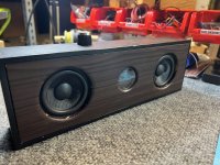
So let’s start with the name, it’s a “coaxial” driver build, or coax, to coax is to be persuasive, these cabinets will be very beautiful and one of my favorite bands R.E.M. have a song called “Pretty Persuasion”. Marketing had a fit over it, they said it was too convoluted so I fired them all and now it’s just me in my garage doing what I want. Makes sense? Alright!

Cost of drivers per cabinet must be under $300 and there are a few other rules as well, check the official thread.

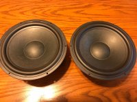
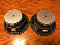
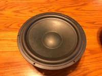
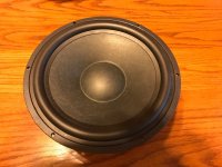
My choice of drivers are the FaitalPro 6HX150 coax ($179 was from online source) combined with the MCM Audio Select 55-5670 8” woofer ($40 each). These model well together and the 8” will have strong response down to 30hz ported and is efficient enough to keep up with the very efficient Faital.

21ec35713466a21f0e269bbd408364c6.jpg


a5c26818d26ce092e4dd5bc56659f4fe.jpg


71528b673d0dd5a755e10cca3f9e603b.jpg


Crossover will be passive as the contest dictates.

Mainly I’m going to be focusing on the enclosure construction for the next few posts. If you’ve been following along my projects over the last year or two, you’ll notice I’m constantly experimenting with new enclosure designs, construction and styles, this project will be no different as I’ll be diving into the world of Kerfing which I’ve never done before.

When I interact with a concept I usually like to do something special with it or something I haven’t seen too much before, and this time I’ll be kerfing solid popular to create a one piece baffle, the enclosure will look veneered but in reality it will be solid wood which I find special/notable.

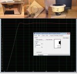
I did a fair amount of testing initially, but this is a piece I did successfully with poplar, my goal here was to determine the optimal kerf depth so that the wood would bend without breaking

97a73aa6464a4ed3798b1d109218e47f.jpg


847d3175ee8d9eb0fd7db1242b8f4052.jpg


This is another test piece, this was more representative of the actual speaker ID building, however it was with plywood, but it gave me an idea of the curve depth with and spacing and what radius curve it would generate. I used an online calculator to get me in the ballpark, then I fine-tuned using this type of experimentation

d4a008b9bc52cac19f09638010239f72.jpg


dd65b49ef99e94f46aba78fcee863e9a.jpg


This is the wood I’ll actually be using For the speakers, as you can see I found two boards so that the grain will be continuous from one speaker to the other from left to right, as you can see the boards are matched across both speakers. This is very beautiful Poplar heart wood.

f67acb8429c233e4430792956de42a9b.jpg


aedc654a71b0d1d2d9ac41d19b6760d3.jpg


Cutting the boards to their rough final length, the length is determined by the baffle width, the circumference of the radiuses, and the lengths of the sides.

b91d66533ba4cfb43160ac95c78445f3.jpg


To create the height of the speaker, these boards were glued together and reinforced with biscuits

ac0ba2e37de0b8d3b464ba596d81d11e.jpg


6a4e3e2464e6a6a44fb209fe34d8fb98.jpg


0c4bf6f7372c43024b491401d62cb536.jpg


dfeb2763841e1c494a9c6acf00203935.jpg


233d7907ce360d434675d3bb27b98ae4.jpg


The glue up,I used Titebond type III which sets up a little slower in case I want work on the alignment, noticed the clamping techniques ensuring the boards are tight against the clamp bars

Once the glue dried after about 45 minutes, I square one end in my panel saw, them the whole panel in the table saw, I have this set up to cut perfectly square and it does a great job

e18340b7bcc31957976a1a809455879b.jpg


aad7aa4a3cdd755169da93eac1e6f9a0.jpg


Getting ready to cut the kerfs, this is a little fixture I built to reference the fence and allow for subsequent fence movements when Kerfing

56971b58c76efdc1921c943c30f88640.jpg


After the first cut is made, each subsequent cut is spaced 5/16 of an inch using this drillbit, then the next cut is made. Stop block is slid over to the fence and then it’s once again space with the drill bit

ca697252c4c951ce45ef62f3fa104ea6.jpg


And so it goes. The kerfs are all the same distance from each end which locks in the baffle width which will be about 12 inches wide. Kerf depth results in about 1/16” material left.

a8cb6a5cf4d0ce9f17b9fc97a6839d01.jpg


67caa6e86f9e551f7ce939afee4e6994.jpg


First board curved and cut, final angle is about 95° which is intentional to gives the sides some rake

27950ff3b377866b1f99e60ae41a0f97.jpg


7df2604be2e30c18418762943b17cfa8.jpg


Both curves done on both sides, again the middle piece is the baffle and the end pieces are the sides

0588070215f6d2569ce195ca0e5aa755.jpg


I created some spacer boards to go in the back to lock in the final dimensions, there will be three for each glue up

bf0937a48427466fffa049ccfa00d533.jpg


Here you can see how perpendicular the assembly is, with some like clapping it’s sits perfectly flat on my workbench

34699796222b01c8660e9958136330d2.jpg


Next up some glue!

Thanks!
Javad
  • Like
Reactions: StevenCrook

Aikido Noval Preamp Muting Circuit

Hello all,

I have an Aikido / NCore setup that gets powered on and off all at once (I know I know...).

The config always had some nasty power on / power off noises...so I decided to add a preamp timer circuit that powers a simple relay to RCA outs. I have the NC of the relay floating, and the NO (timer power to close) direct to rca/amp. See attached...

Power up works great - no noises on power up...but still has a bit of a nasty pop on shutdown.

Concern #1 the preamp out of Aikido to relay is floating while powering up via timer (there is a 1M from output to ground on Aikido board)
Concern #2 the shutdown pop...I could put a 470k at RCA center pin to ground? When all "on" there is the 1M on Aikido and this 470K in parallel, so not per design

Any advice to get Concern #2 shutdown pop to stop? Concern #1 should not be problem, correct?

I worry about damaging the NCore amp modules...

Attachments

  • relay.jpg
    relay.jpg
    37.7 KB · Views: 161

CJ PV8 Preamp Hiss

I'm trying to track down (and eliminate) the source of hiss in a Conrad Johnson PV8 preamp. It occurs in both channels and is affected by volume. I grounded the grid of V6 with 1uF film caps, but no change. So it would seem it's either coming from V6 itself, solder joints in the area, the cathode resistors, or the power supply. I did try tacking in some extra capacitance across the plate supplies, but no change. Many different 5965s have been subbed in without effect. The cathode resistors are all RN65--unlikely that one would go noisy, right? The tube socket has been cleaned. I'll go in and examine the solder joints next, but let me know if there's something (or many somethings) I've overlooked.

Attachments

Newbie Boombox Builder - my first post!

Hey y’all. After lurking these forums for the last few years, I figured I should finally login and post something. I’ve been toying with a bunch of ideas, mostly of the boombox/Bluetooth portable speaker variety. They’re great gifts for everyone I know, and I really enjoy both the technical challenge, and the “cosmetic” challenge!

A HUGE thank you to SO many of you guys, for curating such an insanely-informative and helpful forum that’s helped me countless times. I’ve only been tinkering and building for a year, but I’m looking forward to contributing as much as I can!

Anyway, here’s a few random builds over the last year after starting this VERY addicting hobby!

- Fender Champ BT Speaker: My first project; a 12v Bluetooth speaker for my friends wedding present. (he’s a lifelong musician) PAM8610, 3” 8 ohm Sony “buyout” speakers from Parts Express (I’ve since bought dozens of these $1.89 speakers - they sound shockingly great for small boxes!)

- Mom’s “Tube” Nightstand Speaker: Literally designed for my mom to listen to her podcasts. The tube is purely aesthetic, lit with a blue LED. PAM8403, cheap amazon 2” full rangers.

- Pelican Case On-Set Bluetooth Speaker: I work in film/tv, and slapped together this little 2.1 channel monster for on-set duty. TPA3116 2.1 amp, M38 Bluetooth module. Two 3” GRS full range drivers, and a Drok 4.5” woofer. Powered by single Sony NP-F style batteries; which are commonplace on any set. 8.4v boosted to 12v, each battery gets about 3 hours of full-blast runtime. I’m pretty sure I threw this thing together in an afternoon, and it looks like it. But damn it sounds great, and it’s indestructible!

- Paige’s NYC Dorm Speaker: A portable Bluetooth speaker for my niece’s freshman dorm. 8.4v LiPo, boosted to 12v, powering a PAM8610. Two 2.25” Aiyma full-range drivers, with matching passive radiators on the rear.

- Lastly, a few other random builds; I tend to build lots of prototypes for the hell of it.

Thanks for reading! I look forward to stealing as much knowledge as I can from all of you!

- Zack

Attachments

  • 4DB970EC-2A92-4105-BC96-242DA628AE24.jpeg
    4DB970EC-2A92-4105-BC96-242DA628AE24.jpeg
    780.8 KB · Views: 137
  • 61F5767A-FE77-431F-A39E-169EB68736BF.jpeg
    61F5767A-FE77-431F-A39E-169EB68736BF.jpeg
    520.7 KB · Views: 135
  • 1A0F1C77-26AB-4FC3-9666-9EF16B7D2750.jpeg
    1A0F1C77-26AB-4FC3-9666-9EF16B7D2750.jpeg
    436.1 KB · Views: 127
  • DD9B2301-5496-4F21-9205-FF81B9A29266.jpeg
    DD9B2301-5496-4F21-9205-FF81B9A29266.jpeg
    449 KB · Views: 112
  • F617E2DD-D930-4D6A-9CB6-794A41FFF728.jpeg
    F617E2DD-D930-4D6A-9CB6-794A41FFF728.jpeg
    730.8 KB · Views: 119
  • C57A91BB-7020-488B-8150-9A7386A5230B.jpeg
    C57A91BB-7020-488B-8150-9A7386A5230B.jpeg
    545 KB · Views: 105
  • 0B7EFC58-0458-4ECB-A19B-383410A610D9.jpeg
    0B7EFC58-0458-4ECB-A19B-383410A610D9.jpeg
    563.8 KB · Views: 139
  • 2F395143-6481-4BD5-8D8A-0964463E40AB.jpeg
    2F395143-6481-4BD5-8D8A-0964463E40AB.jpeg
    759.3 KB · Views: 122

Main AC soft start & inrush limiter for a line stage tube.

Hi,

I am going to finish an I/V dac stage made of an expensive ECC88.

I was said it is not realy need for an IHT tube that have less 300 V PS and the filament is solid enough whatever the low impedance at switch on and the inrush due to the use of SS rectification.

I wonder if the use of the cool design from Mark Johnson could do the trick for a better life span of such expensive tube or not ? And allow me to have an only start button in spite of one for the heater and one after for the B+. Or we do not care, i.e. not a 300B, look elswhere ? I understand than cathode will not suffer with IHT with rapid start, I just talking about better lifespan maybe.

Here isnthe board description https://www.diyaudio.com/community/...ncludes-soft-start-h9kpxg.354971/post-6216476

I asked Mark Johnson who send me there to ask to tubes guys... Any inputs appreciated 🙂

Interprete differences Ferrite - Neodynium magnet

In the past I've build several speakers with the little Tang Band 5" wideband W5-1611SAF, which has a ferrite magnet.
I want to explore a new idea and found this driver is now also available, lower cost, with a neodynium magnet, as W5-1611SA.
When I look at the data sheets, they are very similar but there's a large difference in Levc, which I assume is the voice coil inductance.
The ferrite version is 0.023mH, the neodynium is 0.11mH, a factor of 5 difference.
That seems a very large difference; the DC voice resistance, voice coil dimensions etc are the same.
BL is also similar (5.53 vs. 5.18).
Where does the large induction difference come from, or maybe it is a typo?

Jan

Attachments

Vintage Cable from ISODA Electric e. g. HA-20, HY-2036A, HZ-20-D and HB-55 (all Single Wire) - best Way to Connect ?

I have heard from most sellers at those days, that solder connection wasn't a good idea due additional wires consisting of aluminum.

Therefore the question: what is the best way to connect this cable to a plug or terminal ?

Concerning the HA-20 are to read the same question, but without helpful replies:
https://forum.psaudio.com/t/golden-conductors-in-a-vintage-japanese-cable/26577
here a solder connection was created with a 4mm plug
http://www.diybuy.net/thread-1373461-1-1.html

Additional I want to know, what has been tried to achieve with the internal structure of the cable (go to attached images) ?
If I see this correctly, one strand is a relatively thick copper cable, which is wrapped with another cable, which in turn has the same basic structure (i.e. also a copper cable, but a thinner one, which is also wrapped with a very thin wire)

Maybe there are descriptions and datasheet published (maybe also a patent).
Thank you very much for upload such papers and an advice for a solution for connect terminals.

P.S.: Images of HB-55:
https://www.diyaudio.com/community/...5-single-wire-cable-what-other-option.347897/
more URLs:
https://www.ebay.com/itm/403259337836
https://www.htforum.nl/yabbse/index.php?topic=115216.0
https://www.analogueseduction.net/terminated/townshend-dct-isolda-speaker-cables.html
https://www.hifido.co.jp/sold/21-30...0&M=0&LNG=E&OD=0&O=100&L=50&SD1=0&SD2=0&SD3=0
http://www.audiopigiau.lt/produktas/isoda-electric-ha-20/
https://www.hifido.co.jp/sold/10-52914-75585-00.html?LNG=E
https://www.htforum.nl/yabbse/index.php?topic=115216.0

Attachments

  • ISODA HA-20-V.jpg
    ISODA HA-20-V.jpg
    31.4 KB · Views: 303
  • ISODA HA-20-IV.jpg
    ISODA HA-20-IV.jpg
    53.6 KB · Views: 278
  • ISODA HA-20-III.jpg
    ISODA HA-20-III.jpg
    37.4 KB · Views: 288
  • ISODA HA-20-II.jpg
    ISODA HA-20-II.jpg
    370.9 KB · Views: 324
  • ISODA HA-20.jpg
    ISODA HA-20.jpg
    5.9 KB · Views: 292
  • ISODA HA-20-VI.jpeg
    ISODA HA-20-VI.jpeg
    46 KB · Views: 256
  • ISODA HZ-20D-III.jpg
    ISODA HZ-20D-III.jpg
    165.3 KB · Views: 264
  • ISODA HZ-20D-II.jpg
    ISODA HZ-20D-II.jpg
    141.1 KB · Views: 281
  • ISODA HZ-20D-IV.jpg
    ISODA HZ-20D-IV.jpg
    108.6 KB · Views: 266
  • Isoda HZ-20-D kern open.JPG
    Isoda HZ-20-D kern open.JPG
    38.9 KB · Views: 295
  • ISODA HZ-20D-I.jpg
    ISODA HZ-20D-I.jpg
    211.8 KB · Views: 275
  • ISODA HY-2036A-VI.jpg
    ISODA HY-2036A-VI.jpg
    106.2 KB · Views: 296
  • ISODA HY-2036A-IV.jpg
    ISODA HY-2036A-IV.jpg
    110.2 KB · Views: 259
  • ISODA HY-2036A-V.jpg
    ISODA HY-2036A-V.jpg
    78.1 KB · Views: 262
  • ISODA HY-2036A-VII.jpg
    ISODA HY-2036A-VII.jpg
    78.1 KB · Views: 281
  • ISODA HY-2036A-I.jpg
    ISODA HY-2036A-I.jpg
    174.8 KB · Views: 291

Pushing Vhk ratings a little bit?

Perhaps the slightly misleading title will catch some attention😀
I say "misleading" because there is no ratings to be found on this particular tube. Let's start from the beginning: A couple of decades ago when I was new to this hobby, I bought a large stash of NOS 12A6 metal cased tubes from a surplus dealer for very little money. I still have at least a couple of dozens of them left plus a some well suited mains transformers with 12V heater windings and a pair of OPTs that would be a perfect match for a 12A6 parallel push pull project.

The thing that bothers me a little bit is that those OPT's have 15% CFB windings which will put some voltage swing on the cathodes, 40Vpp or so att full power.
Most tubes can take +-100V or so between heater and cathode but the 12A6 datasheet states:
"In circuits where the cathode is not directly connected to the heater, the potential difference between heater and cathode should be kept as low as possible".

There´s not much practical information about the 12A6 online, this is a tube that suffers from seriously low Audiophile Swag, but some of the old Heathkit A7 schematics shows 12A6s being operated with grounded heater windings while the cathodes are at 20V or so.

2. order Chebychev 3000 HZ and 1. order 500 Hz - Why?

I have tried to understand my XO, and asked about it before. I first thought it was a Butterworth or an LR or adjusted to some measurements, since it didn't pass with the values that are in the filter. And I know that you cannot just calculate the exact value, as the impedance is not constant and other things. But since the tweeter is 8.2 µF capacitor and a 0.2 (0.22) mH coil, so it is actually very close to a 2. order Chebychev. If you just use a calculator, a LR generally gives a relatively small capacitor and a relatively large coil, a BUT gives a slightly larger capacitor and a slightly smaller coil and a Chebychev gives a large capacitor and small coil. Just like my HighPass. As I have read it, Chebychev has a Qualityfactor (Q) of 1, and BUT of 0.7 and LR of 0.5. According to The Crossover Design Cookbook by Mark Lawrence, a Q value of 1 is too large and it will sound terrible with a lot of ringing. There are probably many errors with my speakers, but ringing is not an issue, it's a rather polished sound mayby to polished.

What I have read should beeing the advantage of Chebychev should be that it rolls off faster. Then I get confused again. Rolls off faster, that's a 2. order filter, so all the filters probably roll off equally fast, i.e. 12 dB per octave ore have I misunderstod. Ore does it means that the rooloff is more "sharp" when it starts to roll off.
By the way, it also surprises me that by playing a little with different XO frequencies in a calculator and an impedance of 6 ohms, the XO frequence is just over 3,000 Hz. The Bass is cross by a 2.2 mH coil, and then a coil a resistor and a capacitor in parallel with the Bass. So the low-pass filter is probably just a 1st order filter with an LRC filter. 1st order filter with a 2.2 mH coil gives a XO approx. 500 Hz. That gives now sence.

1665383525473.png

What components do I need when using full range drivers and a tweeter?

This is my first time doing anything with diy audio, so i'm confused on what I actually need.
So far I have picked these components

This is the amplifier TDA7498E 2.1
Full range drivers Eminence Alpha 4-8 4" 90-12,000hz
Tweeters Peerless by Tymphany DX25TG59-04

With the tweeters and drivers, do I need a cross over with them? Do I build the cross over or would a premade board work?
Any other tips would be great also.

anyone do a ML-TL for the W8-2145 ?

curious.............

after seeing "Hello, I bought a pair of SDS-160F25PR01-08 and two pairs of Peerless tweeters, TX25BG60-04 and BC25TG15-04 to choose for MLTL, it is possible that you can share me your MLTL design please?" (audiomovil)

then

"Greets!

FYI/FWIW, you got me curious to try HR's wizard, so did a max flat default L*0.349 offset MLTL (61.5" tall/56.36 L/35 Hz Fb) based on a a fairly common 38" seated ear height to the woofer center, though of course all can be adjusted to suit if driver offset is one of these: (L) ~ 0 (top), 0.217, 0.349, 0.424; vent: (L) ~0.651, 0.714, 0.848, 0 (bottom)" (GM)


Tall box though................................

Eclipse TD510s - any possibility of 3rd party repair?

I've just acquired some Eclipse TD510s in good cosmetic condition but non-working. No sound whatsoever (tried 2 amps) and no ohm reading on the terminals. Seems like the voice coils have burnt out which isn't difficult to do considering the low power handling (20 watts).

The drivers are bespoke 120mm full range, and due to the unusual enclosure design / suspension they need to be a perfect fit. I doubt a drop in replacement would work.

TD510MK2_tec20.jpg


Eclipse don't offer any support at all with regards to spares / repair so my only potential avenue is 3rd party. Can anyone recommend a repairer (ideally UK based)?

Cheers

Dawson

1uF+ film / foil capacitor manufacturers (not boutique)

Hi all,

Who else besides Wima makes film / foil capacitors of 1uF and larger? FKPs are sold out at all my usual suppliers. I'd like to avoid the likes of Mundorf, Riken etc. and stick with an industrial manufacturer.

Kemet (Evox/Rifa) do the PFR510 series, but only up to 22nF, PHE448 up to 3.3nF, A72 no stock above 220nF, and R73 also no stock anywhere.

I'd be grateful for any ideas 🙂

Edit: I almost forgot CD "Orange Drop" 716P, but also no stock.
  • Like
Reactions: Capt Grogg

Ian Cacada Re-clocker, DACs, and PSU Feedback

I am considering purchasing Ian Canadas most recent Fifo reclocker and dual mono DACs to build an integrated streamer / DAC. I am interested in anyone who has experience using these boards and can opine on SQ. And I would love feedback on the two PSUs he offers as well - the LinearPi ultra low noise linear PSU and the PurePi Batter PSU - both with ultra caps.

-Chris

Adjustable Short Protection for Quasi Power Output Stage - Teladi EV1000

In the attachment you will find the associated schematic from German's brand Teladi Elektroakustik GmbH.
The power amp unit is the same in the model MV05
Is this a good approach or are there better solutions ?
Thank you for an advice

Attachments

  • TELADI EV1000 Schematic.pdf
    TELADI EV1000 Schematic.pdf
    515.6 KB · Views: 230
  • fcf90936-1c87-49f6-b55a-9364cbfe984d.jpg
    fcf90936-1c87-49f6-b55a-9364cbfe984d.jpg
    72.5 KB · Views: 185
  • d7050a20-c327-499a-ac83-9504a3b1da6e.jpg
    d7050a20-c327-499a-ac83-9504a3b1da6e.jpg
    122.9 KB · Views: 148
  • b0c2da56-ad60-45da-80ec-e170f02d70f1.jpg
    b0c2da56-ad60-45da-80ec-e170f02d70f1.jpg
    97.3 KB · Views: 134
  • 009138c4-a516-4a98-aa99-d77a91a3b032.jpg
    009138c4-a516-4a98-aa99-d77a91a3b032.jpg
    112.7 KB · Views: 157
  • 0d3dacb4-758e-4ff6-bace-7abafdbd99ec.jpg
    0d3dacb4-758e-4ff6-bace-7abafdbd99ec.jpg
    95.1 KB · Views: 129
  • b6d23238-be0c-492a-be42-e7ed495a7e85.jpg
    b6d23238-be0c-492a-be42-e7ed495a7e85.jpg
    102.1 KB · Views: 167
  • 7df500dd-5491-432e-bd97-9cc2602a5138.jpg
    7df500dd-5491-432e-bd97-9cc2602a5138.jpg
    105.1 KB · Views: 139
  • 978c11f2-c140-4747-a70e-879569197964.jpg
    978c11f2-c140-4747-a70e-879569197964.jpg
    88.2 KB · Views: 141
  • 02ae11f7-97d4-4cc9-bab2-2cd97eb191a3.jpg
    02ae11f7-97d4-4cc9-bab2-2cd97eb191a3.jpg
    85.1 KB · Views: 118
  • 61466ebb-1a60-4956-9464-030021679a1e.jpg
    61466ebb-1a60-4956-9464-030021679a1e.jpg
    83.4 KB · Views: 133
  • 22b4a4f3-c5d4-4e6a-bbee-e13f88b6c921.jpg
    22b4a4f3-c5d4-4e6a-bbee-e13f88b6c921.jpg
    92.7 KB · Views: 119
  • 0f84dc96-f090-4549-af00-4a60a33644dd.jpg
    0f84dc96-f090-4549-af00-4a60a33644dd.jpg
    51.2 KB · Views: 153
  • d9795a51-3bca-4753-9138-2120e6b3b9f8.jpg
    d9795a51-3bca-4753-9138-2120e6b3b9f8.jpg
    45 KB · Views: 126
  • eea976e6-4538-4b66-9ed4-dea7715727bb.jpg
    eea976e6-4538-4b66-9ed4-dea7715727bb.jpg
    41.7 KB · Views: 140
  • 54ba3c59-5331-4f43-a02d-6f804fdff3d1.jpg
    54ba3c59-5331-4f43-a02d-6f804fdff3d1.jpg
    45.5 KB · Views: 136
  • 0e8eb0fa-ade1-4ac5-8d8a-71309dad8770.jpg
    0e8eb0fa-ade1-4ac5-8d8a-71309dad8770.jpg
    54 KB · Views: 146

sudden loud buzzing from my 2SC5200 / 2SA1943 amp

Been building an amp around 2 of these for what feels like forever:

UPC1342V 2SC5200 2SA1943 220W Mono Power Amplifier Board Kit HiFi Class A Amp | eBay

(not from ebay, but its the same kit from China)

All was going well (after a few smoke/fire 'learning' moments), had it working for a good couple of weeks while I waited for a few last parts, more heatsinks etc.

As i came to test it prior to my absolutely final re-assembly, the left amp board gives out a very load buzzing, accompanied by a hefty pop when power is cut. The right side amp seems to be fine and plays audio as before.

I've eye-balled the PCB and it looks fine, tried the other power from the transformer and switched inputs and outputs around to the point I am confident the issue is the PCB.

2 things that could have caused an issue. there's a chance a shred of metal from heatsink drilling got in there somewhere, although I cleaned it with compressed air before I powered it up with that in mind.

the other ****-up i made...in the case, i have a PCB for the volume pot about 5mm above one if the caps on the amp, and this 'slipped' and was probably touching the top of the cap, I dunno if electrical contact was made, or if damage could have been caused if there was.

Could this have caused permanent damage? or anything I can do to check it before I order another amp PCB (my 4th!)

List your three favorite hifi amp designers/engineers, and discuss

Looking back on my years in hifi, from sales back in the 80s to rookie circuit repair and "upgrades" today, and all the listening and enjoyment I've gotten out of it throughout my life, I have an appreciation for products from certain designers. I wanted to name my three favorites, and I encourage everyone who reads this to name theirs. And discuss it. Thats part of why we're here.

Here's my top three, no particular order:

- Nelson Pass (and not just because he might see this). His time is limited and valuable yet he still answers questions and participates in DIY camps. He designed the simplest amp I've ever owned, the one that got me into the study of electronics, the Adcom GFA-555. Its my stand-by, my go-to, the one amp I can depend on because there's so little that can go wrong with it yet so much that goes right. Everyone else needs twice the parts to do half the job that Nelson does.

- Jim Strickland (RIP). He designed the Acoustat TNP (Trans Nova Preamp), which morphed into the IRIS preamp after he was brought into Rockford Fosgate's Hafler unit. The IRIS was the second preamp I owned after my Hafler DH110, and it served me well for a decade. A cap refresh turned it into something amazing. I could sell every other preamp I have (I lost count and keep finding them around the house) and as long as I had my modded IRIS to stick in front of whatever amp I kept for last, I'd be fine with that. I didn't find out until too late that Jim lived not too far from where I lived at the time. Opportunity missed.

- Stan Warren (MIA). The mad scientist of Oregon. His PS Audio and Superphon designs were noteworthy, but he had a second career of doing mods on other peoples' designs. I've owned a Warren-mod amp and the changes were the craziest stuff - pronounced "impossible" by a couple of people in the business who looked at it - but they worked. The sound had an unearthly character: crisp like solid state yet sweet like a fine tube amp. If you've never heard an amp Stan upgraded, try not to. You're probably never going to forget it and you'll judge everything else you hear against that one amp. I wouldn't miss any chance to learn from Nelson or Jim Fosgate or John Curl, but Stan Warren is the one guy I'd really like to study with. I have so many questions for him. He and I have mutual friends and I've been trying to find him for years, but that may never happen. (Stan, if you see this, send me a PM).

And because I'm certain no one here including myself is able to keep the list down to three, here's my honorable mentions:

Erno Borbeley (he has had his hands in a lot more than just the Hafler 200, but since almost every other David Hafler amp started right there with the exception of the SE series - I think - Erno's had quite the contribution to my hifi experience)
Jim Fosgate (too many to list but I would start with his original mobile audio designs which turned the industry on its ear, and the man is still going strong in his 80s with Black Ice Audio)
James Bongiorno (RIP, again many designs but the early Sumo is exquisite)
Bob Carver (I was fascinated by the tales of his amp challenge back in the 80s, and years later I had a chance to work on some of his products and own a few. Interesting designs with cheap parts, similar to Hafler but in some cases with far poorer-quality PCBs. Yet where the Hafler sound can be flat to a fault, Carver stuff is just more fun for me to listen to. Both respond well to parts upgrades. Bob's a really interesting guy, kind of a blend of Nelson and Bongiorno, the engineer and the artist. I wish I could afford his new tube stuff.)
Paul McGowan (he knows the business side as well as the design side, and he's a fun person to listen to. His explanations of some basics like transistors and power supplies have really helped my studies)
John Iverson (MIA, quite literally! Electron Kinetics, Electro Research, plus the Robertson Audio Ten Forty and Ten Sixty that may have been lifted directly from his work)

Finally, a shoutout to the unknown designer who came up with the NAD 2150 and 2200 amplifiers and their 1155 preamp. Top flight work, all around.
  • Like
Reactions: d to the g

Audison LRX 4.300 "safe" mode

Hi!
I have a problem with the Audison amplifier. I don't know why it doesn't come out of "safe" mode. I was wondering if the problem was with the power supply or the amplifier. I pulled out 4 rectifier diodes, but the problem persists, it seems to me that it is somewhere in the power section, but I can't find anything. There was a bit of cold solder which I tweaked, but the problem persists.

All measurements were made at a voltage of 13.50V relative to the "-BATT" (power ground).
I think the SG2525AP is broken, but i'm not sure.

SG2525AP

P1 - 2,21V
P2 - 2,66V
P3 - 0.00V
P4 - 0.38V
P5 - 2.02V
P6 - 3.84V
P7 - 1.96V
P8 - 0.30V

P9 - 6.00V
P10 - 3.98V
P11 - 0.00V
P12 - GND
P13 - 13,48V
P14 - 0,00V
P15 - 13,44V
P16 - 5,18V

BA10393 (dual comparator)

P1 - 12,56V
P2 - 2,26V
P3 - 11,31V
P4 - GND
P5 - 12,57V
P6 - 11,31V
P7 - 13,39V
P8 - 13,44V


The schematic screenshots that I added in the attachment are from the LRX 1.400 model (follow the zippyshare link for the complete schematic), which is a monoblock.
The protect section is the same.
Unfortunately, I did not find the LRX 4.300.

https://www30.zippyshare.com/v/5PGBR9Mm/file.html

Attachments

  • SG2525-AP-PIN-4-.jpeg
    SG2525-AP-PIN-4-.jpeg
    61.7 KB · Views: 247
  • SG2525-AP-PIN-5-_1.jpeg
    SG2525-AP-PIN-5-_1.jpeg
    62.4 KB · Views: 195
  • SG2525-AP-PIN-7-_1.jpeg
    SG2525-AP-PIN-7-_1.jpeg
    62.3 KB · Views: 218
  • PRT - temp.JPG
    PRT - temp.JPG
    101.5 KB · Views: 298
  • SG2525AP cir.JPG
    SG2525AP cir.JPG
    174.4 KB · Views: 460

Building an MTM design as a MMT instead?

Hi all,

Very interested in the Overnight Sensation design to use as nearfield monitors in my home DJ studio. I like the idea of the extra bump in output and extension the second driver in the MTM version would provide vs the basic MT, but given the way I would be using/placing the speakers I would greatly benefit from the tweeter at the top at the top of the cabinet with both of the mids below, like you would see on a floorstanding speaker. This would make it far easier to get the tweeters better aligned at my ear level given the short distances from the listening position (3-5 feet). Could there be any serious detriment to the response if I reconfigured the drivers in this way, though?

Coldn't resist: feedback from 4th order lowpass !!

Because there are still many out there who think that it is almost impossible to build PWM amps using post-filter NFB takeoff - I made an attempt to calculate such an NFB loop. I went to the extreme and took a fourth order output filter (f3=50 kHz, Bessel). I publish it here even at the risk that someone will go and patent it. 😉

Just some remarks:

1.) I actually know that real life is real life and simulations are just simulations so I don't want any discussions on that subject.

2.) I know the advantages of self oscillating topologies. I used a carrier-based one because "I come from there" and also because there are many ICs and other solutions for carrier-based class-d around that still use the same boring old NFB topologies.

3.) The same transfer functions can be achieved with alternative circuits. I just used the second topology that crossed my mind. These may even perform better in real life than the one here because they would need less op-amps or put less stress on them. I think I don't have to mention that careful choice of op-amps would be critical in real life.
Because my version of P-SPICE is very restricted I used the voltage-controlled voltage-source model insted of op-amps. It is of course possible to use multiple nested feedback loops instead of the single-loop topology presented here.

4.) I by myself would most probably not build a class-d amp with fourth-order filter because all the component tolerances are much tighter than they would be with a 2nd order filter. Carrier suppresion of 2nd order filters is also sufficient in most cases.

If you have a look a the schematic you can see a classic PID around E1. This one is responsible to build a first-order behaviour, together with one pole-pair of the output filter (ca 70 kHz, Q=0.52).
The second pole-pair (approx 80 kHz, Q=0.8) is dealt with by the circuit around E37 and E10 with the transfer function s^2T^2 + sT/Q + 1.

Because the transfer-function of the feedback-branch is a PD the closed-loop frequency response is a first-order lowpass. I tried with different loads between 2 Ohms and 1 k (nominal = 6 Ohms) and the response deviation was around 0.3 dB at 20 kHz. Deviations were a little "adventurous" above 30 kHz, but this wouldn't be that much of a problem with "normal" loads and clever choice of Zobel values.

On the open-loop gain diagram one can see that the whole loop has a first-order behaviour (well, almost) and the unity-gain point is 200 kHz approx. Phase-marging is 80 degrees approx !

The simulation I would trust the least is the transient analysis (i.e. the THD part to be exact). One can see the output signal when driven 20 dB below full output. There is not very much of the carrier left over ! The FFT shows that all harmonics of the "payload" are suppressed by more than 80 dB.

While the topology as such would theoretically work it is still not complete and it would show a "dangerous" restriction, depending on the input signal. I will elaborate on this later. Everybody is invited though to find that one out by himself in the meantime !

Regards

Charles

Attachments

Haible Subtle Chorus

Hi,

I found some of this boards in my house... 2010! And I will try to build it. But I have some questions.

http://jhaible.com/legacy/subtle_chorus/jh_subtle_chorus.html

You can build the vintage version with HA1457W ( obsolet ) or the modern with standard TL072. And with or without power transistors.

What is the difference of building the version with or without power transistors?

In the BOM of the main board say ( vintage )

HA1457W:

Vintage OpAmp in SIL package. If you don't find these, you
can build a modern version with TL072's (and without power
transitors) - there's a different BOM for this version.
Or, if you want to use the power transitor output stage
without HA1457W's, try other Dual OpAmps in the DIL8
package. I'm sure there are some that will work. (TL072's will
not work in that configuration - there's oscillation on
capacitive load!)

The question is. Worth build the modern version with power transistors? in this case, what IC I can try to avoid this oscillation?

Thanks.

P.D.: I've read somewhere that there are a Burr Brown IC that is very similar to the HA1457W. OPA604 maybe?

FS: Lot of LSJ74B & LSK170B ultra low noise JFETs TO-92

For sale is a lot of the following transistors by Linear Integrated Systems:
  • 100 each of LSK170B (N-channel low noise JFET )
  • 100 each of LSJ74B (P-channel low noise JFET)
The above are replacement for 2SK170BL, 2SK370BL and 2SJ74BL, 2SJ108BL.

A copy of the original certificate of compliance is available on request.

Please send a private message.
IMG_6497.jpg

Attachments

  • s-l1600.jpg
    s-l1600.jpg
    136.2 KB · Views: 157
  • IMG_6498.jpg
    IMG_6498.jpg
    378.2 KB · Views: 149
  • IMG_6499.jpg
    IMG_6499.jpg
    378.7 KB · Views: 113

Phoenix Gold RX600.5 Will not power on

Draws about 1.5 amps, unloaded. No lights come on whatsoever.

TL494C chip DC voltages
1. 0
2. .56
3. .07
4. 0
5. .01
6. 0
7. 0
8. 1.9
9. .05
10. .05
11. 1.9
12. 1.2
13. .575
14. .575
15. .575
16. 0

I pulled the data sheet on the 494 and was expected 5 V on pin 14 and 12 V on pin 12. This amp was built in December 2013 according to the tag. The only PG diagram I can find online is a different unit altogether from 1995.

Thanks for any help or suggestions.

For Sale SBAcoustics Satori Berillyum+TexTreme 3way Speakers

This speakers were a projet built one year ago for a friend.
It is an improved speaker Based on Troels Gravesen SBA941 upgrading midrange to Satori MW16TX-8
Drivers are Satori TW29BN-B-8 Beryllium + Satori MW16TX-8 TexTreme + Satori WO24P-8 woofer
Original SBAcoustics Grilles.

Cabinets were built with 19mm MDF with internal bracing and acoustic absorbers to avoid resonances.
Is was veneered with Zebrano Veneer and barnished with 7 layers of polyurethane varnish with polishing between each layer.

Filters were buil with jantzen Audio Z-Superior + ribbon copper coils at tweeter, Z-standard + air core + iron core with discs at midrange and iron core with discs + cross caps at woofer section.
All internal wires are Janzen Audiuo Silver.

Crossover points are 550 and 1850 Hz LR2
Attached you will see 1/24 octave smoother curves and 1/6 octave as well.
Impedance is 8 ohm and sens around 88dB. An easy load for any amp.

My friend is asking 2200€ + PP fees + shipping.
They are in absolutely SuperB condition, and he is sellind due to his WAF... who doesn´t like them on the sitting rooom.


  • Like
Reactions: manniraj

BBC rear-mounting drive units on baffles

I haven't found anything specifically addressing this on here, so apologies if I've missed something.

I'm intrigued by the BBC technique of mounting their bass-mid drive units on the back of the baffle, rather than on the front as is more usual. It may be a hangover from the 1960s when most speakers had removable baffles and a seal on the front of the drive unit. However even more recent iterations - such as Harbeth and Stirling Broadcast - continue the tradition.

Can anyone point to an advantage in doing it this way? Smoother transition between drive unit and baffle?

For Sale NIB O2 Vfet N channel output kit with NOS Vfet

for sale brand new in box the Nelson Pass O2 N channel Vfet output kit. It will come with pair of NOS 2SK60. Also included in the kit is Mark Johnson‘s Ship Of Theseus power supply filter board. These are now available since I have built the P channel version. Asking $295 Plus shipping to the lower 48 state please.

36FA1E1B-B8DF-44E5-B916-FD8C932CACDE.jpeg

Attachments

  • DF9C9703-C195-41A0-90A1-870A0F314CE9.jpeg
    DF9C9703-C195-41A0-90A1-870A0F314CE9.jpeg
    433.5 KB · Views: 101

Use Audacity as speaker analyzer

Watt pusher used a white noise CD from Denon and free Audacity software recorder to analyze frequency response of a speaker: https://www.diyaudio.com/community/threads/vintage-acoustic-807-pa-loudspeaker-cabinet-rehab.380210/
I can't get Audacity for linux lubuntu20.04 to see any input. I have measured the 3.5 mm phone plug going in the blue jack of PC, 0.92 to 0.95 vac tip to shaft. I have the speaker playing white noise MP3 via media player on the PC. The PV8 mixer sees about -6 db on LED display. The headphone output of PV8 hears the white noise on left channel.
With free download PC software "pulse audio volume meter" I can see sound in the middle of the bars when the white noise is playing on the speaker. That means I think it is going in the PC and being digitized.
With audacity recorded track I am seeing only -1 db spikes every 0.3 to 0.8 seconds. That is with ALSA set to line 0 , then line 1, then mike 0, then mike 1. I'm recording monaural. Audacity mixer board display sees nothing. ???
BTW I started with "roomequalizerwizard" for linux. After downloading, double clicking didn't start it. When I tried to read the .sh file (a script) the text editor said it contained non-text codes and wouldn't display. I've looked at other .sh files when I had a lubuntu problem, they were all text files. So much for REW linux version IMHO.

25Hz for $25!! Dayton 299-114 1301469W

I wanted to try an Isobaric with a removable cylindrical container and made a "one piece motor" by gluing 3/4" x 3/4" rings together. The setup was way better than previous attempts.
1. cut the inter circle first
2. use the waste/cutout to center the piece to the sliding table (2nd pic top).
3. glue together with spring clamps, etc.

Box size, 1 cubic foot with deductions for venting and cylindrical container calculated in.

The woofer is a Buyout from PE, very low cost but well made.
Simulated in WinIsd, clearly shows a response down to 25hz.

299-114 subwoofer speaker features a deep profile, long fiber, high-pulp cone finished beautifully in a protective coating that also dampens resonances. The 1-1/2" diameter 4-layer voice coil's 5/8" winding length maintains plenty of copper in the magnetic gap, ensuring plenty of high-impact, low-distortion output. A vented pole piece reduces performance-robbing power compression, and the magnet structure's extended back plate prevents "bottoming out" the long voice coil. Great subwoofer speaker for any design or application, particularly multimedia systems, small home theater setups, and multi-driver configurations.

Specifications:
*Power handling: 80 watts RMS/160 watts max
*VCdia: 1-1/2"
*Le: 1.61 mH
*Impedance: 4 ohms
*Re: 3.25 ohms
*Frequency response: 35-2,000 Hz
*Fs: 38 Hz *SPL: 83.5 dB 1W/1m
*Vas: 0.55 cu. ft. *Qms: 6.74
*Qes: 0.64 *Qts: 0.59
*Xmax: 4.5 mm
*OD: 6-1/2"

A few more finish steps to go, will be testing soon though.

Attachments

  • 1217.jpg
    1217.jpg
    145.6 KB · Views: 1,372

Which amp for 5 speakers of home cinema? Class D or chip amp?

I built an F5 turbo v2 for turntable and CDs.

Now I need a new receiver to update the new codecs. But figured I'd build my own amplifiers for the speakers and buy a processor. So I don't have to pay for the amplifier part in these integrated receivers which never really got loud enough.

But I can't afford to buy and build another F5 turbo especially considering I need five of them.

So I got interested in class D amps given relatively low cost to build. Then I came across the chip amp for the same reason.

Reading the forums I couldn't work out which would be more appropriate for my needs.

The only source will be digital from streaming services or the PS5 via the TV.

Anyone have any thoughts on the matter and can point me in the right direction? The LM3886 seemed popular...

Thanks.

Subwoofer Box Question

since I went a different route with my amps ect I’m going to build an entirely new setup in my suv .

Wondering if MDF is still the go to wood for building a sub enclosure?

I’ve heard people using Baltic birch ect .

Maybe it was just my ears playing tricks on me that day but I’ve heard a couple enclosures built from birch and didn’t really care for the sound . It just sounded different then an MDF enclosure .

NoQuiPas -- A Truely Dual-Mono, Fully-Differential Passive Preamp with Output Buffers

The Pass B1 buffered passive preamp has been around for quite some time, and has been built many times around the globe.
What is missing is a balanced version of.
And even more difficult is to make it fully symmetrical (eletrically), i.e. truely dual mono.
Just search around in Google for balanced passive preamp, and you will realise.

We mentioned earlier that the guys in Hong Kong want to have a summer amp that does not dissipate too much.
There is already an example of a balanced LM4780 for that :
https://www.diyaudio.com/community/...approach-the-build-thread.208880/post-6271567
But he also wants a matching preamp to go with it.
Since the LM4780 itself has already enough gain, a passive preamp with discrete output buffers, a sort of a balanced DCB1, would be ideal.

So here is the result, even though not quite 100% finished.


220313 NoQuiPas DM4780 MS.png


Enjoy,
Patrick

.

Attachments

  • Like
Reactions: schultzsch

Rockford fosgate T10001bd output stage damage

Hi friends! I come back with another rockford fosgate T10001bd, they tell me that they hit the speaker cables and it started to generate smoke. When checking it I found this damaged ground track, I did a general check and nothing else marked me wrong and when I turn it on the current consumption is high and the output fets make noise. I disassembled them to check them and I found no damage to the output fets and transistors mpsa56 and 06, I measured signals in the ic drivers u202 and u204, but u204 is always sending pulses, but 202 is not, when placing audio both send pulses. It is normal? and I see that the ic of u200 (lm6172) and u203 (tl072) are different greetings and I appreciate your support

Attachments

  • 20220914_161811.jpg
    20220914_161811.jpg
    595.5 KB · Views: 123
  • 20220914_171928.jpg
    20220914_171928.jpg
    377.7 KB · Views: 125

100v Line Transformer

Hi Everyone.
I have an amp that is 4x200w, and I am wanting to make it 100v for some distributed speakers on two of the channels.
The speakers all have transformers in them and are tapped at various wattages throughout each line on these two channels.

My questions come with regards to installing a transformer between the 8ohm Amp and the 100v line.
Will a transformer from an old speaker work? I have a transformer from an old speaker that had many taps/windings, one of which is 200w, the speaker it was installed in had an 8ohm driver. Would this work on one of the lines? Actual load on that line is likely to be around 150w at maximum, which it is likely to never run at. Would this work? I assume you would just adjust the volume of the amp channel to affect the whole line on that channel without causing any issues with the transformer?

If not, what type of transformer should I be putting in here? Any links to actual products would help a heap also.

Cheers,

Linux operating system - practical for test and measurement software ?

I am from the Analog test and measurement equipment era , though I do have two Digital multimeters.
I am intending to buy a Computer , and want an operating system in it which will accept software for test and measurement of audio equipment.
I realise that many audio engineers use Apple/Mac systems though I prefer not that system unless there is no other comprehensive option.
I don’t much like Windows either , thus I am asking here ,
will the Linux operating system accept the various test and measurement software ?
or do the Manufacturers of test and measurement software only design and manufacture for Windows and Apple/Mac operating systems ?

Yes , you are correct , I am really not knowledgeable about computer systems ,
thus any information will be appreciated ,
or a direction to a Thread in this Forum , or to anywhere , where the above has been comprehensively explained.

My Take on X-BOSOZ

It seems there are a lot of people, besides me of course, who have been wanting a good quality PCB for XBOSOZ. Well I have been pointed to several thread and tried to glean as much as I could. This is a completely no area for me, and my first pass at a Pass design. 🙂

First of all thank to all those who have paved the way. They did the real work here, this is very small thing compared to what those people have done.

So thanks to these people in Particular:

Nelson Pass, of course.
Metalman, Terry Aben whose circuit I followed.

But I am sure there are others who deserve credit, and to those I apologize for not knowing who you are.

Anyway they say a picture is worth a thousand words, so here are 2000 words worth.

First the Schematic:

Attachments

  • schematic.png
    schematic.png
    28.5 KB · Views: 12,853

Kenwood KAC-8020 - Looking for DIN control cable

I dug out one of my old amps and remembered why I put it away in the first place:

I need the DIN power/control cord.
I think this is the part #:

Amp: Kenwood KAC-8020
Part # E30-1433-08

It's an 8-pin round connector (din), it is what runs up to the head unit (the input)
If I remember correctly, it also has the remote wire on it.

Any idea where I can get one? I found parts web sites, but most of them say 'discontinued'.

I could probably make my own cable, but I don't have the pin-out information either.

I hate to keep it moth-balled because I don't have the DIN cord.

Thanks,

H.


Here's a picture of the amp and the DIN connector:

An externally hosted image should be here but it was not working when we last tested it.

6AU6 6AQ5 SE Amp Questions

I purchased an assembled 6AU6 6AQ5 SE Amp from China. It worked as assembled but was not correct. The PCB was not correct. I had to cut traces, add correct capacitors/resistors for the voltages and rewire correctly the power supply CRC filters. I have questions about the feedback connections circled in red in the attached picture. I have not seen this before having feedback connected to Pin 2 the suppressor of 6AU6. And I have not seen the R2 240k resistor feedback connected to the suppressor before, but to Pin 5 the plate. Are these connections correct or is this an error too? Or if correct how does this affect the circuit? >>>I have corrected schematic to show 5Y3GT and the added 10uf 400V Capacitor. ALSO Attaching Original Schematic<<<
Updated 6AU6 6AQ5 SE Amplifier.jpg
6AQ5W_Schematic.jpg

Attachments

  • From Website.jpg
    From Website.jpg
    51.2 KB · Views: 439
  • Cut Traces and added capacitors.JPG
    Cut Traces and added capacitors.JPG
    469.8 KB · Views: 377

Question re: RC values for blocking DC at output of simple opamp RIAA preamp

Intrigued by how well my cheap 'n cheerful ESP P-06 build worked out, I've been playing around with an even simpler RIAA phono preamp made with an opamp > passive EQ > opamp. The PSU is repurposed from an earlier Hagerman Bugle build (+/-15VDC, using 7815/7915 ICs).

I believe I have a circuit that 'sounds good'. Now I'm playing around with the output capacitor and pulldown/load resistor.

I've looked around at other similar projects, and have found a lot of variation in values chosen for the output DC blocking cap (Cout) and output pulldown/load resistor (Rload). Many traditional 1980s-style designs use a large value capacitor with lower value resistor. For instance, I found one Graham Slee design which uses 10uF for Cout and 47k for Rload. Rod Elliott shows a few example designs that use Cout = 22uF and Rload = 22k ohms. But then the Muffsy and an ELENCO design use Cout = 1uF and Rload = 100k, while the RJM VSPS uses 2.2uF and 100k ohms. On the other hand, the TNT Solidphono goes to the other extreme and uses Cout = 0.33uF and Rload = 330k ohms, like early 1960s tube circuits would have used.

I'm left with the impression that the choice of values is less important than the resulting time constant. Is that correct?

One thing to take into consideration is the load impedance presented by the device to be driven by the phono preamp output.

- If that's going to be a preamp or amp with a 10k ohm volume control, then a 1uF output cap will result in an F3low of 16Hz, which would introduce a noticeable rolloff of low bass. (Perhaps that's desirable, though, as a rough 'n ready rumble filter?)

- Looking at the other extreme, if Cout = 22uF and Rload = 22k, and that feeds a 10k volume control, even though the resulting load (22k//10k) will be only 6875 ohms the F3low will be down at 1Hz. The Graham Slee values of 10uF and 47k results in F3low of only 0.34Hz, but if the load is a 10k volume control, F3low for that would go up to 1.9Hz. Perhaps that was the design goal there?

Let's say I'm not sure what my RIAA preamp will be driving. It could drive a class D amp with a 10k ohm volume pot on its input, or it could drive my living room stereo with an autoformer volume control (AV) which maintains a very high impedance load. Should I try to find a compromise solution that works OK with both? Or should I optimize for one extreme and assume it will be OK for the other?

I did have 1.5uF and 100k and that was working fine into the living room hi-fi w/ AVC. Into a 10k ohm load the F3low would go way up to 16Hz, but it's not a problem into the AVC.

Now I'm trying a 6.8uF 100V (big) film cap with 56k, which is predicted to have F3low of only 0.4Hz into a light load.
Should I change the Rload to 22k, so the F3low is about 1Hz? Would that conform better to best practices?

What are the pros and cons of bigger vs smaller value C and bigger vs smaller value R in this part of the circuit?

I understand that smaller value capacitors have advantages of lower inductance, lower ESR, etc.
Also, the smaller value of R allows the output cap to charge/discharge more quickly, reducing turn on/off thumps.

PS - Forgot to mention... I've read that a lower value of capacitance (e.g. 1uF) for the output DC blocking cap will have a higher reactance at low frequencies, so can make the circuit more susceptible to picking up hum from its interconnect cabling. Is that independent of the value of Rload? If that's true, and a higher value capacitor (e.g., 10uF) will help reject hum pickup, then perhaps that's an important issue for a standalone phono preamp as opposed to one that's built into a full-function preamp or integrated amp?

Are there other issues of importance?
Projects by fanatics, for fanatics
Get answers and advice for everyone wanting to learn the art of audio.
Join the Community
507,666
Members
7,883,371
Messages

Filter

Forum Statistics

Threads
405,990
Messages
7,883,371
Members
507,666
Latest member
Fpa420