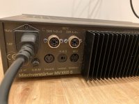
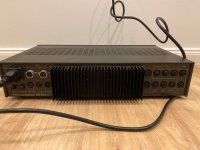
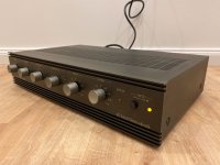
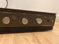
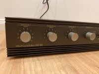
In the attachment you will find the associated schematic from German's brand Teladi Elektroakustik GmbH.
The power amp unit is the same in the model MV05
Is this a good approach or are there better solutions ?
Thank you for an advice
The power amp unit is the same in the model MV05
Is this a good approach or are there better solutions ?
Thank you for an advice
Attachments
-
TELADI EV1000 Schematic.pdf515.6 KB · Views: 238
-
 fcf90936-1c87-49f6-b55a-9364cbfe984d.jpg72.5 KB · Views: 195
 -
 d7050a20-c327-499a-ac83-9504a3b1da6e.jpg122.9 KB · Views: 157
 -
 b0c2da56-ad60-45da-80ec-e170f02d70f1.jpg97.3 KB · Views: 140
 -
 009138c4-a516-4a98-aa99-d77a91a3b032.jpg112.7 KB · Views: 164
 -
 0d3dacb4-758e-4ff6-bace-7abafdbd99ec.jpg95.1 KB · Views: 134
 -
 b6d23238-be0c-492a-be42-e7ed495a7e85.jpg102.1 KB · Views: 177
 -
 7df500dd-5491-432e-bd97-9cc2602a5138.jpg105.1 KB · Views: 145
 -
 978c11f2-c140-4747-a70e-879569197964.jpg88.2 KB · Views: 149
 -
 02ae11f7-97d4-4cc9-bab2-2cd97eb191a3.jpg85.1 KB · Views: 122
 -
 61466ebb-1a60-4956-9464-030021679a1e.jpg83.4 KB · Views: 148
 -
 22b4a4f3-c5d4-4e6a-bbee-e13f88b6c921.jpg92.7 KB · Views: 126
 -
 0f84dc96-f090-4549-af00-4a60a33644dd.jpg51.2 KB · Views: 160
 -
 d9795a51-3bca-4753-9138-2120e6b3b9f8.jpg45 KB · Views: 132
 -
 eea976e6-4538-4b66-9ed4-dea7715727bb.jpg41.7 KB · Views: 148
 -
 54ba3c59-5331-4f43-a02d-6f804fdff3d1.jpg45.5 KB · Views: 141
 -
 0e8eb0fa-ade1-4ac5-8d8a-71309dad8770.jpg54 KB · Views: 149
Last edited:
This is an old timer. To its credit, it allows you to set the current limit by measurement, instead of a ballpark value. But the pots are in series with the base, where the threshold is set be the transistor VBE more than the series resistance, so it adjusts the sharpness of the current limit more than the threshold, and the speed. There are two potential problems, should the pot be set close to zero resistance.
1. If the base resistance is too low, then a sudden output short could destroy the current limit sensor transistors.
2. With a low base resistance, even a rational value of say 100 Ohms, and no collector diode, the current limit transistor collectors become forward biased when the amp is driven in the opposite direction, so it steals drive current from the VAS and clamps the drive voltage.
Like many old circuits, it's a hack that works in a limited way. To do this properly, the current sensor pots should be wired as a divider pot and not just in series, with a fixed resistor limit, and diodes in series with the collectors.
But a ballpark value as is common today is probably the greater wisdom. I should also mention that reliability issue with any pot that might render the circuit useless after time corrodes the pot contacts. Some may point out that this is only current limit and not VI protection, but VI protection has stability issues so I would avoid VI limiting.
Transistors are cheap today so I would update the circuit to something similar to the now classis "blameless" circuit, but only if you are more interested in playing with it than using it.
Terrible very dated design.
Wire a 220r+100r voltage divider across each 0.22r ballast resistor, the 100r touching the speaker out line in each case, and BC107/177 short protection transistors BE junctions across the 100r ones.
Circuit will limit peak current ~9A , which is fine there for that supply, transistors, and possible 4 ohm load.
EDIT:
Last edited:
Thank you. Fig. 6+7 under
https://www.angelfire.com/sd/paulkemble/sound7.html
so as Fig. 1+2 under
https://www.renardson-audio.com/protect.html
show such an approach
check out the sites under
https://linearaudio.nl/safe-operating-area-calculations
http://hifisonix.com/wordpress/wp-content/uploads/2013/05/soaprot_12-03-2012.pdf
- also pdf attachment (AES paper) in post #2 under
https://www.diyaudio.com/community/threads/overload-and-short-circuit-protection.121323/
"Audio Power Amplifier Output Stage Protection" (Eric Mendenhall)
for detailed explanations
I actually only asked the question in post #1 because I was of the opinion that this topology might be pursuing a special approach resp. a special goal (never seen before anywhere). Poorly designed circuits were less common in old devices than in new ones, but they were still relatively common.
Last edited: