Denon DRA-1024RA repair

Hi,

Got a Denon DRA-1025RA on the bench. It plays, but since I got it I noticed that the stereo separation is lousy. It has a "mono" button and "Simulated stereo" which I thought may be the problem, but noticed that the bass control does not work at all.

Disassembled it to find the bass control is physically broken. The nut that holds it to the chassis was not tight and I guess over the years it snapped guts.

VR402, part number stamped on it is 2110536006, and 30KCX2.

Service manual has an additional number of V1620V30FC303K with a description of 30Kohms BASS.

Any idea where I can find a replacement?

For now, I may just put two (well, four) 15K fixed resistors in there to simulate being in the center of the range.

Thanks!

Parts list for Quad ESL 63 EHT board

Hi Everyone,

I recently traded for a pair of Quad ESL 63's (US studio version). The problem one is currently having is that it's playing back at reduced volume, no pops, hiss, crackles, or distortion, just reduced volume. (the neon bulb isn't flashing every second, I only get a flash when I first turn it on) After thumbing through the service manual it seems like it's probably the EHT board. I would like to rebuild it with slightly beefier components and I was wondering if I could get some suggestions from those who are more familiar with the 63's.

I know you can buy pre-done boards but, where's the fun in that? (and I'm a little on the broke side at the moment 😛 :-D )

According to the service manual the Caps are 10nf -20 +50% at 2KV
would moving up to a higher voltage rating be worth the extra money, and perhaps switching to metalized polypropylene?

The diodes are 1AV30's these are the specs I was able to find online for them:
I(O) Max.(A) Output Current 10m
V(RRM)(V) Rep.Pk.Rev. Voltage 3.0k
t(rr) Max.(s) Rev.Rec. Time 300n
@I(F) (A) (Test Condition)
@I(R) (A) (Test Condition)
V(FM) Max.(V) Forward Voltage 15
@I(FM) (A) (Test Condition) 10m
@V(RM) (V) (Test Condition)
I(RM) Max.(A) Reverse Current 2.0u
@V(R) (V)(Test Condition) 3.0k
I(RM) Max.(A) Pk. Rev. Current 5.0u
@V(R) (V) (Test Condition)
@Temp. (øC) (Test Condition) 75õ
Semiconductor Material Silicon
Maximum Operating Temp (øC) 80’

Would a GP02-30-E3/73GICT-ND work as a replacement?

And should I change any of the resistors on the EHT board? and if so do you know what wattage I should get, I didn't see it mentioned in the service manual.

Thanks

Rockford P6002 output FET measurements

Hi guys,

So, working on my first P6002.
The amp has some trouble with the output fet/ drive circuit. I'm a bit confused by the measurements.

I removed all the output cards/fets, and the amp powers up just fine.
In case of the output fets removed and +-41v rail voltage, there is approximatelly +28v and -28v on the gate of the output fets.
When driving a 40Hz sine wave into the RCA's, there comes a very clean square wave signal on all the output fets gates, with a DC voltage of the above +28v or -28v (high side and low side banks)

When soldering in new fets (1 per bank), the +28v and -28v on the high/low side gates changes into positive or negative rail on the output fets gates.
No square wave signal present anymore on the output fets gates, and full negative rail on the speaker terminal.

I don't get it. This should be a class AB amp right?

Attachments

  • PHOTO_20220427_210854.jpg
    PHOTO_20220427_210854.jpg
    556.9 KB · Views: 114

Philips CD560 Capacitor Mix Up

I have two Magnavox CDB560 (Philips CD560) decks that I am recapping. My first foray into such a project, and I am a newbie on the Forum.

These decks are one step below the CD650 in this product line's lineup. I've compared the schematics for the 560 and the 650 and the main boards are almost identical for electrolytic capacitor values and locations, except for about 3 locations. The other big difference is the CD560 has LM833 Op Amps while the CD650 has NE5232N Op Amps.

Two capacitors mounted on the boards do not agree with the schematic. The Philips CD560 service manual schematic has Caps 2305 and 2309 as 1uF and 2.2uF respectively (Decoding 1 diagram). However, these are reversed on both 560 boards, i.e., 2305 is the 2.2uF and 2309 is the 1uF. I checked the service manual for the 650, and that schematic agrees with the 560 service manual schematic. One 560 deck was manufactured in January 1987, and the other in June 1987, so it seems that Philips kept building them with the capacitors reversed vs. the published schematics.

I have no idea which is correct, the actual manufactured boards or the schematics. So I have two questions I hope someone knows and would be kind enough to answer. Which is correct, as manufactured or as published? And does it make any difference if they are reversed?

For Sale Kirmuss ultrasonic record cleaner

Hello
I’m selling a very lightly used Kirmuss system.
Asking$675 shipped conus.
Contact me for more details if interested
It’s literally like new.
Thanks for looking and have a great day.

Attachments

  • 54A8789C-267F-476E-B2EC-19A8094CC0DB.jpeg
    54A8789C-267F-476E-B2EC-19A8094CC0DB.jpeg
    294.5 KB · Views: 131
  • 26E6A51E-6069-459B-A089-434A60E1884A.jpeg
    26E6A51E-6069-459B-A089-434A60E1884A.jpeg
    659.4 KB · Views: 121
  • 7D83E6AA-80AB-4AC3-8090-E7AD43FC8D9B.jpeg
    7D83E6AA-80AB-4AC3-8090-E7AD43FC8D9B.jpeg
    390.5 KB · Views: 126

New simple amplifier

Replacing the output pair in JLH with a complementary pair and adding a pair of diodes in the offset , I got a conventional push - pull amplifier circuit with the following parameters
4F742E47-C328-4B4A-AFC9-E1B96CE9392C.jpeg

TND 0.52% at 5V amplitude.
By replacing the Q2 transistor with a composite one, it was possible to significantly improve these parameters without compromising the simplicity of the circuit.

56963432-EF0C-4416-8371-3F638857B532.jpeg


A8709E37-A412-43CC-BE70-AFEBF9B0B16C.jpeg


280EC8C3-3782-406E-A0E9-25A558295979.jpeg


And this is practically only the second harmonic. Quiescent current 0.87A
at 8V TND 0.0091%
That's what I wanted to introduce you to.

P.S.
The inscriptions on the diagram are for 4 ohms , the TND graph is already for 8 ohms 0.0044%
38C42E91-ADB5-49D9-83E7-A4666CA87DAC.jpeg
  • Like
Reactions: Ciro82 and dkfan9

For Sale BPPBP - Bruno Putzey's Purist Balanced Preamp

Well, this is another project waiting on the shelf... and I will let another person to finish it.
BPPBP - Bruno Putzey's Purist Balanced Preamp consisting in:
PCB Board with all SMD components populated (came from the DIYAIDIO GB)
All through hole components:
Nichicon caps (Muse BP, Gold and HW for PS)
Neutrik XLR inputs/outputs

All the compononets you need tu fully build this preamp.
Never used not opened.
The only missing component is the JST iAC inpunt connector

Price (+PP fees + shipping):
100€ with LM7815/7915 regulators
120€ with Hypex regulators


Suggest a speaker style/type/size for this room

I would like to tap the brains trust at diyAudio about suggestions of what type of speaker design you would use for this room? It is a 6Mx9M high vaulted mud brick room, I would like to hang suspended speakers from rafters at the far end of the room, as there is not a convienient location on the ground to place floorstanding speakers. It will be to mostly play background music for enjoyment, not critical listening or high SPL requirements.

IMG_20221003_085230.jpg

Adding RCA low level input to high input only subwoofer - Vandersteen 2W - RC4136N

I reverse engineered the schematic here and I'm struggling to understand all the circuits and how to modify it to work with low level RCA inputs.

I believe I need to remove the 12.1k &1uF caps on each input because they're low pass filters, increase the value of the 5.11k resistors to increase the amp gain and remove the 12m & .0039uF and .033uF caps? correct?

Link

Low power 2 W @ 8 ohm, 4 - 16 ohm usable simple, class A SE - any recommendations?

I would like to build some low power amplifiers to power midrange and HF horns. My priority is absolutely zero hiss and hum with 110 dB/W.m drivers. A PCB or kit form would be great. I will need 4 channels in total

I was thinking about the Death of Zen headphone amplifier without the output resistor. That one looks like it fulfills most of the needs - the 4ohm operation is not mandatory.

I would like to have SE class A, since most of the time the amps will be in the milliwatt range.

I would like to avoid chip amps and class D unless there is a proven stellar performer.

I would prefer single supply with a coupling capacitor - the value will be selected to protect the drivers and also may be a part of the crossover for the HF horn (or the only crossover for it).

Edit: It needs to have enough gain to reach full power at consumer HiFi level.

Thanks for any suggestions!

Inside Cabinet Speaker Cable Causing A Big Difference in Sound

Hello

So here is a short story.

I built Markaudio Pluvia 7.2HD with Pensil Cabinets. I used some cheap sommerclabe in the cabinet and also on the outside where i connected it to the Class D amp.

So then i decided to buy Mogami 3103 cable and test them out. I kept the Sommercable in the speaker cabinet while only changing the outside cables to Mogami. The difference was huge, Soundstage was very deep and wide and tone was much more smoother and transparent. So was very shocked how much difference it made.

So after this discovery i decided to also change the inside speaker cables that are in cabinet to Mogami to improve the sound further. After i did that the sound wasnt smooth anymore it got brighter and a bit sibilant and soundstage totally changed again.

Why would changing speakers that are inside cabinet have such a drastic difference in sound? What about comercial speakers that usually use very thin wire as most people only change outside speaker wire.

Is it because of amp load? capacitance? inductance?

Would really like to understand whats happening here and whats causing such a big difference?

Spud-Assist: Totem-Pole Current-Mirror PP Hybrid

Or; 1.5 watts from a 417A spud amp.

Here is a concept I've been playing with, which is a current-mirror
circuit using totem-pole (series push-pull) topology. The idea is to
drive an active load so as to produce a current swing into the
external load exactly opposite the amplifier tube signal current
swing, thus dividing the load between the amplifier tube and the
active load.

In the test amplifier schematic below, a 417A is used as the amplifier
and a DN2540 is the active load. The 68R resistors on either side of
the external load connection function as the AC load current divider
between the bottom device (tube) and top device (MOSFET). The top
68R also sets the idle current as per CCS. In practice, there is a little
loss due to the finite Gfs of the FET, and the R values can be tuned
for a load split > or < than 50/50 between tube and MOSFET.

When the tube is driven to greater conductance, current is sunk from
the load and the voltage drop across the lower 68R increases,
causing the MOSFET conductance to decrease by a proportionate
amount. Likewise when the tube is driven to less conduction, the
voltage drop across the lower 68R decreases, causing a
corresponding increase in MOSFET conduction, sourcing current into
the load.

In this way, the tube sees only a fraction of the load (here it's about
1/2) as the tube and MOSFET are basically in AC parallel driving the
output transformer. The tube sees about 4K anode load in this circuit
(actually closer to 3.5K due to the above mentioned loss).

There is an advantage over SRPP in that the signal current swing is
balanced for any external load. This makes it a good driver for
reactive loads, like the headphone/miniwatt amp here. Current
source capability could make it a good driver for an A2 power stage.
It's also a way to get better anode efficiency from CCS loaded
parafeed circuits.

When I get more time, I'll make some measurements of distortion
etc. but it's mostly f2 until you get over 1 watt, then some f3 and
above show up.

I'm actually able to get 10V p-p into 8 ohms (1.5 watts) by driving the
417A grid positive. The current mirror works fine into A2 as it senses
anode current and just follows the tube.

Michael

Attachments

  • spudassist417.png
    spudassist417.png
    9.2 KB · Views: 3,165

Is this a good speaker configuration?

I'm making plans for a soundbar with sattelite speakers. It's going to have 4 3" drivers in the front then a left and right sattelite speaker with 5" drivers. I want the sattelite to unplug easily so I have it connected with terminals.

The 3" driver is a Dayton Audio PC83-8
The 5" driver is a Dayton Audio PA130-8
The amp is a 160Wx2

I have the schematic posted also. Will this work correctly?

Attachments

  • Speaker wiring diagram.png
    Speaker wiring diagram.png
    15.3 KB · Views: 123

Modifying(upgrade) ProAc Studio 200?

Hello.

I wanted to get experts' opinions on something I'd like to do. I have been using ProAc Studio 200 since early 1995, and finally found that the foam edges of 18W8542 woofers were all cracked. I looked for some info. to replace or fix them, and found that options were $15/pc kit or $65/pc driver repair, or $2xx/pc driver replacement(could be cheaper, I guess). That just made me think that putting $300 or $900 to worry about the same thing 9 year later is not favorite. So, I changed my mind to replace all drivers and crossovers to make a new speakers. As I am poor at tools and woodwork skills, I just want to replace drivers which can be mounted in place of 18W8542 and seas 1" soft dome tweeter. I also believe I will have to redesign crossover for driver changes, but not sure even with redesign, I can get the right alignment of bass with existing enclosure and new drivers. But I want to try anyway.

Could you advise me whether this is feasible or not, which drivers to use, how to design crossovers, and internal dimension of Studio 200 enclosure, etc.?

I am looking forward to your kind advices.

ACA Mini clone - Black Edition

I employed the services of Prasi to draw up a layout of the ACA Mini, taking inspiration from Mark Johnson and of course the Nelson Pass design.
Boards were made 1.6mm 1oz hasl from JLCPCB. The BOM is as per the other layouts.
Small silkscreen error on the output transistors. Reads 530 and 9530, should be xx20.
I don't know if the multi turn trimmers I used were handed different, but following the set up instructions, fully CCW gave me full bias and VO so I needed to do the opposite and go full CW.

I can offer 12 spare boards at £8.50 UK or £10 ROW delivered. Just to recoup some of the costs.

IMG20220919160149.jpgIMG20220823172517.jpg

SB Audience Bianco 15 spider resonance and fix?

PS EDIT, I mean basket and not 'spider' in this post. The basket is resonating... Sorry for the mix-up.
I just received a pair of SB Audience Bianco 15" open baffle drivers. They are cheap, but have promising data. The first thing to do when taking out the driver is tapping on the cone... Sure enough I can hear this driver goes deep. The 15" pro driver it replaces has a much higher pitch to the tapping sound. BUT...there is a spider basket resonance ringing like a bell in the background. Checking with a FFT app using my phone I see a peak around 170Hz...
So up with the Pico Scope and sound pressure meter and measure. I get driver Fs at 34Hz, driver out of the box, never played a note, so that is reasonable I think. Electrically I see nothing peaking around 170Hz.
Tapping on the cone and using the sound pressure meter's mic I get this FFT after several taps (Scope on 'peak hold').
Snag_8244695.png
Snag_8234840.png


So I feel this driver is actually well made. It is cheap and the basket is pressed steel. You get what you pay for. I think the focus has been on motor and cone, while the money is being saved on the basket. Which is actually good because the basket is what a diy'er can most easily do something about. I have decent enough tools to make plywood stringers to re-enforce the basket spiders. I even have carbon and kevlar fibers and epoxy. But I think it will be plywood attached with Sikaflex. The inside of the basket spider will receive a thick coat of Sikaflex. I think this should dampen out the spider resonance and also strengthen the basket to be a bit better.
Any thoughts on this process?
Thanks for constructive comments.

Attachments

  • Snag_82307cc.png
    Snag_82307cc.png
    25.8 KB · Views: 136
  • Like
Reactions: profiguy

Advantage of beam triode over simple triode

I am using 6HS5 beam triodes in my high voltage amplifier.
As suggested in the data sheet, I connected the beam plates to the cathode (see 'Characteristics and Typical Operation' section).
There is surprisingly little info on the 'net as to what the advantage is of a beam triode over a 'normal' triode in terms of performance.
Does it make it more linear?
I haven't been able to find a data sheet with curves.

Jan

Attachments

SE KT-77

My latest single ended amplifier. First built for some old EL-34 tubes I bought on Ebay but decided to bias the amplifier for a pair of Gold Lion KT-77's. Those old EL-34 tubes do not sound that good, tired. I have had the KT-77's a few years and they have not been used that much. Still in the process of biasing it for the KT-77's so more details soon. Right now I am running 47ma of current with 428V and for me that is a little too hot. Roughly 20 watts dissipation for a tube rated for 25 watts. There may still be a tiny bit of red spotting on the plate of one tube. Really hard to tell being that it is on the back side of the tube and it may just be a reflection but I would still like to see 17 or so watts of dissipation for long tube life.

Attachments

  • P1040106.JPG
    P1040106.JPG
    309.2 KB · Views: 150
  • P1040105.JPG
    P1040105.JPG
    437.7 KB · Views: 148

Speaker Spade Crimping

Is there a tool that I can get that would allow me to compress/crimp the speaker spade so that the OUTSIDE dimension is a little more narrow?

I am trying to fit a an existing speaker spade into an amp post that has a little plastic tightener (Cary Amp) with a gap that I insert the spade. It may be a little too small and need to squeeze the spade 0.10/2MM inches. Just don't want to use a standard pliers. So basically get from 15MM to 13MM outer dimension.

Beta 8CX in PA application

I need to repair two home-built PA speakers. The original speakers used 8” woofers and a dome tweeter (which I recognize is not suitable for PA use). The surrounds of the original 8” woofers have deteriorated. The boxes appear to be well-built 0.75” MDF. I’m thinking of replacing the 8” drivers with Eminence Beta 8 CXs, the Eminence ASD1001S for the HF driver, and the recommended Eminence crossover.

But I note that the same crossover is recommended for three different HF drivers, and this suggests that some compromises are made (but are these significant in my application?). Can anyone recommend a different combination of HF driver and crossover? I might save some money if I build the crossover myself, but I need a design.

I plan to seal the box (1.2 ft3) . I calculate an fbox of about 80 Hz and a Q of about 0.33, and this speaker will not get much low-frequency energy anyway (these speakers have a dedicated amplifier and EQ, and the speaker is used in a side fill application).

Tom

TDA 7293 -- done right ?

Hello everybody . I have read through a large number of threads and I am aware that it will be difficult to come up with something new as both the LM 3886 and the different versions of the TDA series appear in a good many of them.

But I still would like to start a new thread about the TDA 7293 in particular because I think that there is a lot of potential in it provided it gets the same kind of attention and dedicated effort the 3886 has got for so many years.

On the other hand I do not like the sound of Class D amps at least for now but looking around it seems to be the future trend. I do not want to say there are no good ones around but I prefer analog amplification.

I think there is a trend to active speakers at the same time there is an ever growing number of so called "digital" amps . Just as with LED lighting the magical word lately seems to be efficiency, not perfection anymore. Eventually this might lead to the dying out of traditional chip amps though I hope it will be a long while as yet. But their price will rise........

So to get back to my starting point and TDA 7293:

If all the people here in this forum were to get together and design both an optimized circuit and optimized PCB for a modulat system based on the TDA 7293 where one could add one or two of the chips , then bridge two of those , so driving the TDA by a buffer that can invert or not we could not only get the very maximum out of these amps but possibly help other folks as well who now buy any one of those EBAY-and/or Amazon sold SUPERAMPLIFIERS from China .

Make a one time recipe to cook up an excellent TDA7293. Concentrated in one thread with the obvious advantages for people new to all this ?

What do you say ? Michael

Telefunken TC-450M room for improvement

I can't change the title so I make here an update on the topic which abandoned the initial Telefunken deck mods in favour of a Denon DRM 700A.

have this deck for about 5 years, never used , not even tried it until today...I suspect it wasn't used for at least 20 years before that.It's manual specs...modest.It's transport...simple and modest, but in working condition right out of the batch. It's sound right out f the shed : although a bit too much hiss when no noise reduction is used really f... good and I mean it! The needle vu-meters...hypnotic. It's schematic... discrete for most of it leaves some room for improvement and it's also a very serviceable deck.

You can find a lot of photos and videos over the internet on it.The Tapeheads forum would probably be the place to discuss it...but I am going to start working on it right here.Replacing a lot of capacitors...no problem.A taste of the 70's cassette deck technology guaranteed.Any good suggestion appreciated.
I have much better decks in terms of specs and functionality except having a Hicom NR system, but not many that are much better good looking.I think it deserves all my attention.Possibly my germanium headphones amp will find a place inside..

Although the tapehead looks like a very nonlinear one in need for too much damping, I think this guy has a lot of potential.
There's also an ideea I might wanna try as I never heard anyone trying it and the playback section already suggests it can be worked that way: trying to make it a total current feedback damping design.Not sure I have the right ideeas at this moment, but something makes me think it's a better way to work with highly nonlinear tapeheads.I really welcome any ideas heading that way or better.

Attachments

  • telefunken tc450mlineout+reg.png
    telefunken tc450mlineout+reg.png
    677.9 KB · Views: 373
  • telefunken tc450mHPamp.png
    telefunken tc450mHPamp.png
    626.1 KB · Views: 339
  • Telefunkentc450Mhicom.png
    Telefunkentc450Mhicom.png
    361.2 KB · Views: 282
  • telefunken tc450mPBamp.png
    telefunken tc450mPBamp.png
    343.1 KB · Views: 358
  • 20220710_141607.jpg
    20220710_141607.jpg
    569.5 KB · Views: 350
  • 20220710_141640.jpg
    20220710_141640.jpg
    566.6 KB · Views: 431
  • 20220710_141731.jpg
    20220710_141731.jpg
    647.4 KB · Views: 339

Musical Fidelity A5.5 Amplifier Help Needed

Hello all.

Don't want to create too lengthy a post so I'll keep it brief.

An opportunity arose in me acquiring an A5.5 amp for what seemed a bargain price and the amp was shown to me working so I jumped at the chance. On getting the amp back home, I noticed from the screws that hold the lid on, that someone had been inside so, thought I'd have a look myself just to ensure everything was fine. Inside, everything looks fine apart from that one of the fuses were blown. The thing is, the amp still powers up fine and produces good sound from both channels. I'll try to add a photo or two shortly but I'd appreciate any input that can help me. Thank you.

Please help identify STD01N STD01P

Hi, I have some pairs SanKens transistor without any datasheet found.
They are
STP01N
STP01P

If anyone has see or maybe used these transistor please help me, my meters say they are 2 transistor in one package common collector

Please any thought are they two power transistor or combined driver + final power transistor?

The picture attached

I also have STD03P & STD03N & they are different kind

Attachments

  • IMG_20221010_155202.jpg
    IMG_20221010_155202.jpg
    317.1 KB · Views: 239

Help with a Technics Crossover

Hi All,

The story - I aquired some SB-AA2 Technics speakers (8 ohm, 160W music, 80W din). The person I got them from said one of the Tweeters were blown. After searching for a tweeter replacement, I found an original one and purchased it. In hindsight, I maybe should have tested first. I connected the tweeter and still no sound coming from it, then realised, no sound was coming from the Mid speaker. Interestingly, I noticed that the tweeter is connected to the mid speaker (seems to be common in some of the Technics models Ive looked at). When I disconnected the Mid speaker, the tweeter came to life. I measured the ohms on the mid speaker and it was reading open.

So, I thought on my working mid speaker, I would get that mid speaker and try it in the speaker box that had the blown mid speaker. It didnt work and upon checking that "working" mid speaker, it now reads 5 megaohms, rather than the 8 ohms I measured before testing it and of course, doesnt work anymore.

I have bought 2 replacement mid speakers, but I dont not want to connect them before I figure out why the good mid speaker blew.

I took the crossover out and checked all components. They are fine, Cap is measuring correctly, inductors are reading (but I dont know the actual value of them), and the resitor is bang on the value.

As there is no technical information for this speaker model, I reverse engineered the crossover to make a circuit diagram for it. I did find a very similar crossover design from the SB-F555 speakers, but a few components missing compared to mine (but had the same wiring colors as my speakers).

However, what I cant understand is that the mid and tweeter polarities are crossed, meaning the Positives are wired directly to the negative input from the Amp, and the Negatives are on the components side of the Positive input. The diagram will show what I mean.

My questions are:
1) Can anyone see a reason what would cause the mid to get destroyed from this cross over design?
2) How does this work correctly with the +/- side of the speakers reversed (is this something to do with "Linear phasing"?

Thanks all...

crossover-circuit-diagram_SB-AA2.jpg

All FET class AB Pushpull for Yaesu FT75B

I am restoring and modifying a vintage Yaesu FT75B hybrid SSB transceiver. The receiver channel is completelly solid state, but most of the crystal oscillators and mixers was replaced from BJT to JFET with a notable improved noise reduction of the audio recovered. The tx stage includes 12BY7 and 6DQ6 tubes but still remains inoperative.

The original AN214 was burnt and I decided to make my own audio amplifier including only MOSFET and JFET too but maintaining the original japanese spirit. The mini amplifier then was build and mounted in a piece of protoboard in the IC place.
It gives about 1.5W from 2 x 2SK941 MOSFET biased class AB with only 25mA for both transistors. The exciter is a dual JFET 2SK150 as phase splitter and a 2SK117 as CCS. A NFB loop reduces the audio BW to not more than necessary for clean and comfortable listening. Note that this amp isn't for hifi, too much bass and trebble aren't desired for SSB listening. The 22nF in the primary also reduces high frequency responses.

Power MOSFET 's are very "pentodic" so the NFB reduces the output impedance. Bias is about 1.6V got from an internal regulator in the tranceiver. No heat sinks are needed with 13.5VDC until well past the 100mA bias current.

Output transformer is 600+600 turns 0.15mm wire bifilar, the secondary is 120T 0.5mm. No insulation needed between them. Core area is 8 x 10mm using plastic bobbin.

Attachments

  • FT75.jpg
    FT75.jpg
    343.5 KB · Views: 210
  • Trafito.jpg
    Trafito.jpg
    315.4 KB · Views: 136
  • Ampli.jpg
    Ampli.jpg
    433.2 KB · Views: 192
  • Squema.jpg
    Squema.jpg
    296.4 KB · Views: 197

DAC necessary when using Optical out on desktop on-board sound card?

One of the reasons people streaming from their computer use an external DAC is to get rid of the noise inherent with using things like analogue audio out on your desktop pc, or things connected trough USB. "Inherent" although I'm not sure how big of a problem it is.

I'm using an optical out to my Onkyo TX-NR535, so my digital signal gets converted by the Onkyo DAC. Now I'm not saying this is some hifi DAC, but this probably eliminates any possibility of PC noise to get into the signal. Is this correct?

I'm not chasing some superclean signal BTW, my source is often youtube. So are there any serious (and yet affordable) gains by buying a seperate DAC and going analogue to my amp? Or not really?

Thanks
VIncent

Original JBL control SB 5 driver .... what can i do with these?

After being itchy hands of modifying my JBL control sb5 subwoofer unit with other china unit drivers ... i am left with the original units hanging around (total of 4 pcs 🙄)basically doing nothing around my storage area 🤣 they actually and originally configured using tri chamber 6th order bandpass system ... i wonder if what i could come out with something different with these drivers? from the looks they dont seem to be very solid build but their sound is indeed very solid ... i am thinking of ported for these drivers but they dont seem to have very long throw ... any other ideas? thanks

Attachments

  • 307583005_3397241430489207_7653731853533558431_n.jpg
    307583005_3397241430489207_7653731853533558431_n.jpg
    228.9 KB · Views: 190
  • 308008821_3394297880783562_4151365063048085552_n.jpg
    308008821_3394297880783562_4151365063048085552_n.jpg
    121.4 KB · Views: 152
  • 309007133_3397241350489215_8445856612006688241_n.jpg
    309007133_3397241350489215_8445856612006688241_n.jpg
    42.9 KB · Views: 169

Power supply for both preamp and power amp

Hello,
my question is really simple and straightforward (maybe a little bit stupid) but I couldn't find any simple answer anywhere. What is common solution to powering both preamp and power amp? (I'm talking about really low power ones). To be more specific, if I want to build a PAM8403 based little amplifier and I also want to play with that sound i little bit before, so I need some preamp. What is the best way to power it all when PAM8403 needs +5V and preamp needs something like ±12V? (Maybe ±5V would be enough in this case). I mean make totally separeate devices? Make one device and separate power supplies in it? Or is there any simple solution to have common power supply for both?

Thanks everyone for advices and experiences, I really appreciate it!

Open baffle MTM questions

I had question about OB.
Is theoretically possible to design OB speaker with U-frame and with MTM speaker element configuration in way that it goes down in -3dB point to about 100-150 Hz, had narrow front panel and is missing dipole peaks and minimums in range 100-1000 Hz?
I mean can asymmetric U-frame rear part help to avoid dipole peaks and minimums? Or at least to get smaller peaks and minimums?
I had made some simulations in Akabak with asymmetric real part U-frame, but still all had big peaks and minimums, nearly independently how asymmetric rear part of U-frame is.
Did I want impossible thing or still is some way to get rid of peaks with asymmetry?

Attachments

  • OBSimu1.PNG
    OBSimu1.PNG
    163.3 KB · Views: 699
  • OBSimu2.PNG
    OBSimu2.PNG
    100 KB · Views: 707

Aliens, if they exist, must have some form of speakers. Physics applies to all of universe. How they can operate?

  • Much different than our speakers?
  • do they have audiophiles? i guess so
  • How did they come up with their speaker tech, tried all the concepts we are using?
  • Can they hear much below 20Hz and way above 20Khz?
  • Do their speakers weigh more than their bodies? ---> Extremely unlikely!
What if we could ASK aliens, how to build the perfect speaker? or at least ask for some general suggestions?

Guess what, you can actually ask and receive answer, but without any 100% guarantee the answer comes from true Alien.
Worth trying anyway, huh?

Finally, something you dont know for sure. There is a guy name Darryl Anka. Remember the pop singer from Canada in late 60s, Paul Anka? Darryl is his cousin. So Darryl is EXTREMELY and i mean truly top 5 on this planet intelligent fellow. With vast psychological knowledge, way beyond all others.
he has unique business, he is doing "channeling" sessions , live to audience. Basically repeating what an Alien nickname Bashar transmits to his brain via telepathy. Bashar says he is from Essassani race.

Ok, to the point.... Anka once said on their planet they have music, but its much more simple than ours.

Bashar wanted to communicate also, humans are "masters of limitations" in the Galaxy. Also, to follow your passions to the best of your ability until you cannot take it any further. Sounds familiar?

Equivalence theory

I'm having trouble getting my head around it.

Within a vessel in the absence of a gravitational field, virtual gravity is created by acceleration of the vessel. The speed of light on the other hand, measured between a source/receiver couple on the vessel moving in the 'falling' direction is affected by the average velocity, rather than the acceleration.

Two light signals separated in time take a different length of time to reach the receiver on the accelerating vessel due to the instantaneous velocity at different times, whereas a conventional mass 'dropped' within it will fall as it would on Earth.

How is it that this also happens to light in a situation static to a gravitational field, ie from the top of a tower to the ground?

2or3way

Im building my first diy speakers and cant now decide howto proceed. I have pair of seas l22rnx/p(8" woofer), peerless 839903(5" midbass) and foundtek cd 2.0 (5" ribbon tweeter).

1. L22rnx spec. says 25-2000hz so basically I could do more simple 2way with fountek(2kHz crossover). But I have read that some says 3kHz would be better.
2 So I was thinking '3way' and 3kHz for peerless/fountek + biamp seas separately, use it for low bass freq only e.g. 100-120hz. Some old posts says also that with fountek its good to have "small" 4-5" midbass so would 2way work with seas 8"? And what you think about 3way option?

Of course I could try both options but I can build only 1 speaker cabinets.

Rear ported speakers can benefit from diffusers?

Hi, I have a pair of Klipsch RF82 ( https://www.klipsch.com/products/rf-82-floorstanding-speaker ) that have rear ports.

Will the placement benefit from rear diffusers like these ones: http://p10hifi.net/FH/download/EdHorn-deflector-230607-map.pdf ?
Will it be easier to place them closer to the walls behind them? Is it possible to predict how and if the bass will change?

Thank you in advance,
Roberto

Epilepsy and migrene vs. HiFi

Hello friends,
I coudn't find a thread about these nasty conditions that may be problematic considering listening to live music and HiFi with speakers and headphones at home.

I have had some migraine episodes for decades, but recently had my first epilepsy attacs and was diagnosed as an epileptic. I'm now 62, and brain EMG and EEG showed an infarct scar and typical epilepsy waves. Preventive medication was started, with Trileptal, statin, aspirin etc. Now I feel fine, and haven't had symptoms. I have never had any problems with light or noise etc. provocation, episodes and attacks come unexpectedly. But anyway, I must be careful and I will avoid loud noise eg. outdoor or club concerts with loud PA and strobe lights. And I lost my driving license for at least a year...

How about you others? Epilepsy starting in childhood is obviously more difficult, but nowdays we seem to have many effective drugs that don't have nasty side effects. How about music and hifi?

A PS for multiple mono-TPA3255 amp boards that comes with a lot of headroom

Ah, now this should do the trick! 😀

https://www.trcelectronics.com/mean-well-power-supply-shp-10k-hv

The 55V model can be adjusted down to under 50V. Perfect for powering a multi-channel amp consisting of N TPA3255 in PBTL mode (each can deliver 480W mono into 2R). On paper, this is good for powering 20 channels or so, with a little headroom to spare!

Class A P-P Output Tube Bias

A general question on tube biasing a P-P output stage with a pair of KT150's. My amplifier is in prototype with an ElectraPrint 60 watt 6K OPT with a 3-ohm tap (my speaker is a flat 2.5-ohm impedance for most of the 30-20k) and the mains is 360V 650mA. The amplifier design is balanced only input to a pair of SRPP 6SN7's then to the output stage, which is fixed bias.

When I set the bias to 140mA (90% of max dissipation) with a 4-ohm resistive load the B+ draws down to 450V and the load line per VTADIY shows both valves fully conducting. The scope shows clipping at the OPT secondary at 19 volts (45 watts average which corresponds to the VTADIY calc of 49 watts class A).

When I set the bias to 65mA, the B+ is 470V and the load line shows Class AB. The output clips at 37 volts (162 watts average, which is 2x the VTADIY max g1 voltage swing). Also, the transformers are barely warm instead of 45C at Class A.

I have not seen any Class A PP high output power tube designs, all of the KT** PP designs I see are biased from 35 to 65 mA, and that pentodes are run Class A mostly in SE.

My question is will operating a pair of KT150's in P-P Class A be a problem for the valves? The operating point closest to the max dissipation line at 140mA is 400V so I can bias lower to 135mA so as not to exceed 90% dissipation during signal.

If the tube will be okay, the only other concern is with heat generation at the dropping resistor in the power supply, which measures 70C on the pcb around the resistor, including the cap cases -- and the prototypes are uncased in open air. Casing it without a fan is probably not a good idea. But I'm more concerned with the price tag of the KT150's.

It's also a tough call because at 140mA the sound at low volumes is spectacular. On the other hand, at 65mA it rivals my Mark Levinson 20.6's in terms of sheer slam and dynamics on orchestral recordings, but loses that magic with small chamber/jazz music.

thanks,

Upgrade Switching Power Supply - What Beats Nexus NX-3000?

Hello all, I'm doing a complete teardown and rebuild of my 16 year old Zero One Audio Mercury CD/HD player. This was precipitated by the failure of the CD drive, replacement of which means I had to disassemble the entire unit; while I'm in there I'm recapping all the boards, replacing the HDD, and adding some ferrites to key places for RF mitigation. The motherboard uses a Celeron processor running Linux, and the unit has always had very good sound quality.

Although it hasn't failed, the 16 year old switching ATX power supply (Nexus NX-3000) is probably a bit long in the tooth, and I'm wondering if there is currently a lower-EMI/RF, less noisy ATX supply I could swap in. Attached is a picture of the supply showing it's specs. Back in the early 2000s this was a highly-regarded supply, but time marches on and I'd like to know if there is a more modern supply that would be an upgrade. I want to stick with switching as I do not have room for a massive linear supply.

Anyone had good luck with a current replacement?

Attachments

  • Nexus NX-3000 (2).jpg
    Nexus NX-3000 (2).jpg
    366.7 KB · Views: 117
  • Nexus NX-3000.jpg
    Nexus NX-3000.jpg
    518 KB · Views: 104

Mengyue mini valve amplifier

hi i have one of these little amps it is the EL34 version i must say the sound is very good i paid £160 for it. the guy who had it before me had changed the valves but he said he never ajusted the bias. i am hopeing that it is a fixed bais, as i have not a clue were to start with byassing has an y one got one of these amps
all help would make me very greatful

Vertical mosfet thermal stability verification

The new version of the “common base input..." (https://www.diyaudio.com/community/threads/common-base-input-for-power-amplifier.387450/) amplifier includes a new design of the output stage to make possible the use of vertical mosfets (IRFP240/IRFP9240). The figure below shows a simplified version of the relevant part of the circuit. The output is adjusted by sensing the current into the ballast resistors using properly biased bipolar transistors (those shown in the simplified schematic). The 4 rightmost mosfet devices in the figure are the ones actually doing the voltage drive into the speaker and operate in open loop. It was done this way to minimize current spikes in the crossover region. As mentioned in my previous post the prototype works as expected and a final thermal stability test was done leaving the amplifier operating for several hours at 60% of max power. Originally the bipolar transistors (common base) were attached to the heat sink in close proximity to the output devices to provide thermal feedback, but it was removed due to a very slow thermal oscillation that I considered an open door to thermal runaway. Considering that the bias current is sensed on the resistors (and not on gs+resistor as usually done) there is still a significant amount of thermal feedback: if the temperature of one of the output transistors increases, current will increase in all devices due to a reduction of the threshold voltage, that increase is sensed by the current control loop that in turn will force the gs voltage (in all mosfets) to get reduced in order to maintain that current constant. The problem is, I have no way (given my skills) to demonstrate that the circuit is thermally stable. I would appreciate any help regarding how to predict thermal stability (or instability!).

Attachments

  • amp_thermal.jpg
    amp_thermal.jpg
    9.9 KB · Views: 142

Deaf Bonce AAB-2900.1D slowly charges rail caps then finally starts

Purchased this amp a couple weeks ago.

Arrived with fake irfb4115s (reworked). Rdson of those parts was in the 170mOhm range. Also bridges we're blown, irs20957s chips likely bad, and some rc filter damaged.

I have legit irfb4115s in, new bridges and all else patched up.

The amp has a couple issues with starting and running above 14v though.

It takes considerable time to start, the power supply pulses, LEDs all blink, and rail caps slowly charge, it starts eventually. I removed the rail caps and they measure ok. They are back in now of course, didn't run amp with them out.

If I get it started and run it over 14v, the power supply waveform goes from good looking to a narrow high amplitude pulse and current draw decreases from 1.3A to about .7A and bounces around. Rail voltage remains ok, but is clearly in unhappy state. 7524 driver chip becomes quite hot.

Was considering ordering driver chips but the waveforms look the same on input and output when acting up.

Any ideas?

Thanks

Attachments

  • PXL_20220929_210245816.jpg
    PXL_20220929_210245816.jpg
    423.6 KB · Views: 209
  • PXL_20220929_210254691.jpg
    PXL_20220929_210254691.jpg
    426.9 KB · Views: 187

Technics SL-P555 no VFD

I have no display at all on this.

FL601 is driven by IC601. I have verified the fuses between pins 1 & 2 and 47 & 48 and some voltages, but the pins are way too close together for me to be able to safely probe while the machine is powered on.

ICP 11, 12 are good.

Diagnosing VFDs and digital sources is a bit beyond me. I've verified the above and correct voltage on all regulators and that's about as far as my knowledge goes.

Can anybody help?

I made a small WAW with Fostex FF85WK

Preface:

I don't truly need any new speakers and currently only really listen to one pair, my large 5cu.ft TD15M + CD-waveguide boxes with DSP and dual 50ASX2 boards. This is in my living room and is used for TV, movies and music. On my home PC I use headphones (MDR-7506) as it is usually late in the evening. I do have a small setup at my work office that I listen to sporadically, depending on whether I get to sit there a bit or have to run around the place all day. The speakers were small reflex for the titular FF85WK. These are OK, but I never really designed anything decent for this driver (did lots of wacky and unorthodox boxes for them OTOH) and neither have I ever done a WAW, so why not?
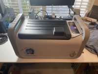
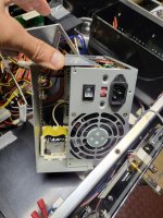
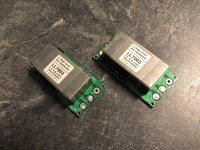
Here's the build:

In case anyone's just here for pics or a visual TL;DR. 😉

waw_a.JPG
waw_b.JPG

How this came together:

Due to the aforementioned lack of need for new speakers, I was not going to invest much money into this. So I wanted to see if I could design something from the modest stock of parts and materials I have at home.

To put the first "W" in WAW, I had three options:

- Peerless 830869 8": I had these in MLTL in my living room before bringing the TD15M juggernauts up from the basement. The XO I designed back then wasn't so great, so I parted these, but kept everything. These would be good for a WAW and I may yet make one with them, but I wanted to go smaller with this project and I don't see these in anything less than 18L or so.

- Faital Pro 6FE100 6": Their suspension is stiffer (lower Cms) than specified, so Fs and Qt are predictably much higher and not usable in a vented box. Even sealed with Qtc~1.0 is larger than I want for this project and even then, f3/6/10 are fairly high.

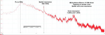
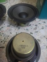
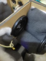
- Fane Studio 5FRK 5": I got a good price for these a while back thinking I could use them with the parted HF module (BMS 4540ND + 6" JBL PT-waveguide) from the MLTL. That plan did not pan out. I would need to notch a ~4kHz peak on the driver, which I'd be willing to, but the directionality mismatch was more than I cared for considering the complex crossover. While it truly is more of a midrange driver (medium-hi Fs and low Qt), it also has a quirk around 800Hz-1kHz, see below.

5FRK_fr.png
5FRK_z.png

It shows up on both frequency and impedance response. To be fair it is present on the spec sheet and I knew about it. I did not investigate whether it is audibly deleterious. This should be attenuated or out of the way for all but the highest "typical" WAW crossover frequencies.

From my T/S parameter measurements, I modeled various enclosures in Hornresp and had a few options in the 6 to 9 liters range, just about what I'm looking for.

The mid-tweet chamber:

I'd previously tested the FF85WK in a straight 3" pipe, 12" of length, stuffed, to be used as a mid-TL to damp the impedance peak and had great results, quite similar to what Dave P10 achieved in some of his own builds. I knew it would be more difficult to implement something like this in an enclosure of the desired size, so instead went with a sealed chamber. I used a 4" ABS pipe union (4.5" ID). I caped it off with a, well, pipe-cap for a volume of 1 liter and tested different amounts of fiberglass insulation and go the following.

mid-tweet_chamber.png

The mid-TL gets the magnitude lower, but the single peak of the sealed chamber is at a slightly lower frequency. This should work out since my planned crossover isn't too low, as we will see next.
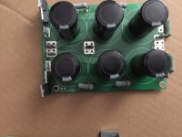
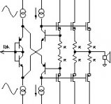
The crossover:

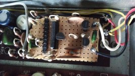
I have a small quantity of caps, coils and resistors over a typical range of values and really was aiming for something usable from my pile. I think I succeeded, though not without compromise, but that can be changed if I ever so choose. I really was limited by the inductors, as I'll explain.

I knew I could not aim for something as low as 250-300Hz; I don't have monster coils nor do I plan to shell out for them. I thought ~650Hz was nice as it is roughly the geometric mean of the human hearing range - not that there is anything magic about crossing there. I had a ~10L enclosure I used for testing before, so just gave it a new baffle with some 0.25" hardboard, slightly braced, added some lagging and stuffing, mounted the 5FRK and the mid-tweet chamber. I quite fortunately ended-up having the exact width of my final enclosure, which I did not really get to pick.

After a few sessions of annoying everyone including - especially - the dog with sine sweeps, I had something decent.

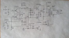
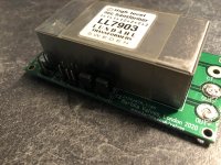
The 5FRK got a Zobel and its low-pass is 2nd order, via two coils 1.5mH + 1.6mH summing to 3.1mH and a 30uF shunt capacitor. The coils are small-gauge and combine to a DCR of slightly more than 2 Ohm, which isn't so bad here. The 5FRK is already more sensitive than the FF85WK and I've never used high amounts of BSC, so can deal with a slight reduction of its SPL. The raise to its Qts of 0.32 is not unwelcome too, considering its medium Fs. The 2nd order really is necessary on the 5FRK unless I notch its 4kHz peak. I tried 1st order, but it affected the response too much despite being seemingly far in the cut-band.

The FF85WK would have to be high-passed 1st order, as I was then out of suitable inductors to give it a 2nd order. 30uF achieved the intended ~650Hz target, but there was a bit more interaction from the impedance peak than I wanted. I ended-up using a shunt 16 Ohm resistor to further damp the peak as seen by the capacitor. It worked well enough without lowering the minimum impedance too much.

Here what this looks like.

crossover.png

The enclosure:

Using Hornresp, I was considering a straight Augspurger DCR, as well as one with modified Vb/Fb ratios, but ended-up going with a simple reflex. 7-8 liters tuned around 60Hz looked good to me, with a well-damped response. Since this project has been about using what I have on hand, the same went for the boxes. Remember the dismantled Peerless MLTL's? I'd built these from 18mm BB-ply and I don't need to tell you how the price went up considerably for this material. They happen to have a CSA of 12" x 7.5", suitable for a bookshelf facade. I thus took two 6" sections from them on my table saw, giving me just under 9 liters of gross Vb to work with. The mid-tweet chamber takes away 1.25 liters alone. The enclosure is roughly of GR proportions, only ~0.25" deeper, but the FF85WK chamber, bracing, crossover board and vent make it highly irregular in shape.

For the new back and front baffles, I went with 11mm "birch" ply. Ok, that next bit I feel bad about. I'd always bought 11mm BB-ply at the same big-box store for around 20$ for a handy-panel, 2x4 feet, but it's been many years since my last purchase. I knew the price had gone up to about 40$ for this item, just walking by the aisle. So I go there, find a panel with clean outer veneer, in the same bin it's always been, pay up and go home. They used to call it "Russian birch ply" IIRC, but now it was just "birch ply", but I did not pay attention to that, though I should have. When I started to cut it, it smelled like pine and comparing it to old cutouts of actual BB-ply I had, I noticed 2 or 3 fewer lamination. So I paid a premium for birch-faced pine ply. The stuff isn't unusable for a small speaker, but I still feel I've been had. I had to use it anyway as I'd already cut it up.

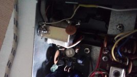
The ABS mid-tweet chamber is glued to the baffle with epoxy, bracing it, as well as epoxied to the side and top and braced to the far side. There is a horizontal holey-brace tying the sides and rear baffle together, about half-way up. I think I made the most of my pricey cheap ply... I've added some felt on various internal surfaces, but have to wonder how much it helps for a driver playing mostly below 650Hz. The mid-tweet chamber's fiberglass filling and felt lining nearer to the driver is likely sufficient for the FF85WK, which also has a healthy rebate to its mounting hole.

I went with a slot vent, 3" x 0.75", about 4.25" long. I assume my final Vb is closer to 7 liters and it is tuned to 58Hz.

system_Z.png

There may be some R in the vent if I go by the above system Z response. We can see the 16 ohm shunt on FF85WK does not lower impedance to much, never getting below 5.8ohm.

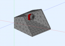
The 5FRK is horizontally centered and vertically at GR, while the F85WK is horizontally at GR, coincidentally equidistant from top and nearest side, not ideal but I believe I partly mitigated this with the bevels.

I had planned on large lateral bevels to show-off the BB-ply end-grain, but that's not happening with the ply I got, though I still want the bevels. These are 1.41" on the sides and 0.71" at the top, cut on the table saw. I had to fill some voids in the pine ply there. The FF85WK at the very least looks like it is not equidistant to side and top anymore. I did not measure a before and after the bevels horizontal and vertical polar response, that would have been too long for something I was not going to change at that point.

The outer birch veneer still looks good, so I wanted to at least keep that. I painted the rest with porch & floor paint, poppy-seed colour. I primed with BIN shellac before that. Runoff are visible on the baffle where I assumed I could sand it out, but the veneer is incredibly thin. The tung oil made that particular cosmetic defect a bit more apparent. Oh well. I think the overall look still turned out good.

Final measurements:

5ms gated response at 50cm, both enclosures:

200-20kHz.png

Ungated response at 25cm:

nearfield_25cm.png

Not certain how meaning full it is, but here is an interior nearfield ground-plane response, hoping to demonstrate the LF behaviour:

ground_plane.png

It's close to the HR simulation to be fair. I'm just not sure what the 30Hz dip is about, but it did not show-up on a lower-res sweep from 20-20kHz.

Step response:

step_response.png

We here see I had to invert one driver to allow for the asymmetrical slopes. I had to compromise here if I was to avoid buying more inductors. 😉 I also thought this more acceptable than the somewhat worse response of the 5FRK with a 1st order.
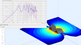
Polar response:

polars_hor_0-90.png

VituixCAD Directivity (hor).png

It is mostly that of the FF85WK naturally, plus the specific enclosure, as the crossover is well before any of the drivers become directional.

All in all a pretty humble design and build IMO, though I did spend quite a bit of time on it. WAW's may be simple, but they're not necessarily easy. I learned some more as always and am more aware of my design choices and compromises.

This post turned out larger than I intended and it's late and I can barely think or type anymore. I'll post subjective evaluation (FWIW) anon.

24 channels USB to I2S interface (with Source codes, ASIO/VHDL/Schematic)

Hi Now I'm making my USB-I2S interface.
I made stereo and 8channel USB-I2S project 2007 and 2008,
https://sites.google.com/site/koonaudioprojects/usb-to-stereo-i2s
now expanding to 24bit 24 channels.

attached
(1) Board photo, UM232H module / IDT72V FIFO / DLP-HS-FPGA2 / Clock, Power, Buffer
(2) Schematic.
(3) VHDL source, single, about 800 lines. 1300 FFs.
(4) ASIO Host Driver source, about 600 lines. (ver 0.1! I want to tune)
(you need ASIO SDK and free VisualStudio to build)

Hardware
FIFO can be changed to Cypress or faster one, if you want synchronous speed.
FPGA module can be changed. maybe GameDuino, Lattice Brevia, etc will work.
Clock, more can be added to switch 44.1/48/88.2/96.
Isolation, you can add IL711 isoLoop.
Power supply, is your free choice.

Software
by looking into source code, you can find only some lines are specific for FTDI. and 90% of codes are for ASIO. the core is to make data format for the device, then write them to the device. about 40 lines.

VHDL
I only uses very simple VHDL, to understand / to modify. If you can read state-machine, you can read.

Now you have all materials to start your own, don't ask me - please DIY and enjoy🙂

Attachments

  • Board_Photo.jpg
    Board_Photo.jpg
    112.4 KB · Views: 3,309
  • SCH02.png
    SCH02.png
    176.8 KB · Views: 3,562
  • main.vhd.txt
    main.vhd.txt
    36 KB · Views: 701
  • koonasio01.cpp.txt
    koonasio01.cpp.txt
    17.1 KB · Views: 491

Anyone with a dead Philips CDM-X mech they want to resurrect?

Recently I've been looking into replacing the laser diodes in the aging Philips CDM-0 to CDM-9 series CD mechanisms. I found that all the radial armed mechs, right from the first generation CDM-0 of the early eighties to the end of the line CDM-9 of the nineties, used the same laser diode. I was surprised, I kind of expected to see a change over the fifteen or so years these mechs were around.

Anyway; I managed to get hold of a bunch of brand new laser diodes of the same brand and model, complete with 'bling bling' gold cases. However, I don't have any suitable candidate mechs at the moment, so:

Does any of you out there have a tired old CDM-0, CDM-1, CDM-2 or CDM-3 which you want to have an new lease on life?

I'm interested in replacing the laser diode on mechs where:
- The laser is truly worn out, not the electrolytic capacitors in the player. Too many times the laser is blamed when it is the servo's fault.
- The mech has been treated properly (especially in regards to static precautions). Static discharge destroys photodiodes, there is no way to rescue a static damaged mech.

I essence, I'm looking for mechs where the laser is at fault, not something else.

I'm offering this for free, hopefully there are a few people out there that are keen and have mechs that fit the above criteria. I'm quite excited about this experiment, as if it is successful, we could get a lot more life out of the radial armed mechs yet!

I'm only keen on trying the earlier variants at the moment (CDM-0 to CDM-3), the later variants are more compact, and I don't even think the diode is replaceable for some CDM-4s, due to the construction techniques used.

Attachments

  • P1030263.JPG
    P1030263.JPG
    102.3 KB · Views: 1,442

Please recommend Hi-Fi speakers for JBL MX1500 tower

this is all data and my pictures found about this towers
https://picasaweb.google.com/101674986737083658341/JBLMX1500
https://www.axacter.com/mx1500.pdf

nominal Impedanse 4ohm
rekomended amp 10-125W
Freq 40Hz - 25kHz
Sensitivity 90dB / 2.8V / 1M

internal volume of 50 liters 220x260x870 thickness of board 1.5

crossover 900Hz 3.5kHz
woofer A0708A 210mm woofer 25mm voice coil 3.4ohm
mid A0704A 100mm 20mm voice coil 3.0 ohm
tweter A0701A 5.7 ohm
port tube 70 mm diametr x 145mm

Yamaha CDX-1060 with 1-BIT DAC

hello,
i want to use this yamaha cdx1060 as dac, and connect them to a streamer.
the dac chip is YM506 and it is 1bit as datasheet said.
i tried to connect this ym506 with my streamer via i2s pins.
but it didn't work, only noise sound appear.
(i guess because of that 1bit dac chip can not accept directly common 16bit pcm)
how to connect them properly? pls help.

thanks.
Peter

Attachments

  • 1BITDAC.png
    1BITDAC.png
    111.4 KB · Views: 229
  • blockDiagram.png
    blockDiagram.png
    145 KB · Views: 199
  • connect.png
    connect.png
    801.3 KB · Views: 325
  • 1BITDAC2.png
    1BITDAC2.png
    305.2 KB · Views: 210

Lots of high end matched pair capacitors in different values, 50% off MSRP

LATE spring cleaning, hopefully finding new homes for caps I can't foresee using again. I can confirm capacitance and send you a picture of the read out on a multimeter if necessary. These were all bought as true matched pairs from Parts Connexion, Jupiter, Hificollective, etc. Let me know if you want a single instead of the pair. MSRP is in parentheses (current list prices from Parts Connexion, VH Audio, etc.). Plus many others lower in cost -- see pictures

Jupiter copper foil 600V 0.22uF matched pair $70 ($138)
Cardas Golden Ratio standard leads, 0.22uF $50 (???)
Fostex 3.3uF $93 ($186) -- unsoldered leads
SOLD Vcap Odam 2.2uF $93 ($186)
Vcap Odam 3.3uF $98 ($196) -- unsoldered leads
Angela (Jensen) Copper Foil, aluminum case $32 ($64) -- have 3 total
Jupiter HT 2.2uF $88 ($176)
SOLD Mundorf silver / gold / oil 3.3uF ugly, soldered extension leads $100 ($312) -- measures perfect, sounds excellent, no worries about the leads

IMG_1039.jpg
IMG_1040.jpg
IMG_1041.jpg
IMG_1042.jpg
IMG_1043.jpg
IMG_1044.jpg
IMG_1045.jpg
IMG_1046.jpg
IMG_1047.jpg
IMG_1048.jpg
IMG_1049.jpg
IMG_1050.jpg
IMG_1051.jpg
IMG_1052.jpg

Attachments

  • IMG_1037.jpg
    IMG_1037.jpg
    588.8 KB · Views: 122

L15Dsmd in an old Adcom amp chassis

I just finished up this little budget class D amplifier project. My main goal was to use some spare parts and to see what a $15 amplifier board powered by a $20 power supply could do. I used an old Adcom Gfa-535 chassis with a pair of LJM L15Dsmd amp boards powered by a pair of $20 -/+48V Smps with some surplus capacitors. I was pleasantly surprised when I powered it up and it actually sounds pretty darn good! I do have one issue I’m trying to figure out. When I connect the amp to my SMSL SU-8s Dac which has a built in smsp and 3 prong power cord I get a sort of fluttering noise in the tweeters when I get close to the speakers. I do not get this noise at all when using a Dac(Topping Dx3pro, Nuforce HDP….etc) with an external walwart type power supply with a 2 prong non grounded power cord. Any ideas?
B27417CD-0CA1-4AB0-AEB1-BF84A917B542.jpeg
BADC3AB8-702E-4854-A2A3-6BF163E6B321.jpeg

Electrocompaniet AW 180M adjustments

Hi all,
I almost fixed a (...completely...) broken EC AW 180M.
Adjusting dc offset & bias was quite trivial.
R44 for bias current (9-8.5mV across 0.2 ohm restistor = 45-42.5mA as the working one)
and R7A to null dc offset before ouput relay.

Now there is a third trimpot (R6P) on the so called "Sister Board" near IC protector.
EC firmly but kindly but refused to give me any help or hint 😡 .
Amplifiers measures and sounds good but ...
Is there someone who can give me any help?

Thanks in advance

For Sale WTT - Jelco heavy brass weight.

This was on a tonearm I picked up. Looking to trade for the stock dampening fluid cap as it's going on a suspended table and this one is much heavier.

I'll look for more info on the piece, essentially the heavier weight has multiple sonic advantages over the stock one.

Please reach out if you're at all interested and I can send more pics and information. Will have to be a trade or help me source the stock piece as you need one or the other.

Attachments

  • PXL_20221011_192645551.jpg
    PXL_20221011_192645551.jpg
    286.1 KB · Views: 90

ferrite-cored output inductor on a class AB amp?

Some people don't like ferrite-core inductors for audio applications on the theory that ferrite can saturate and make the inductor could behave nonlinearly, generally losing inductance at higher currents.

This is a real concern in a speaker crossover where significant voltage appears across the inductor at audio frequencies.

What about the amplifier output inductor on a typical class AB amp? This is normally sized around 1uH. It stops the amp from breaking into ultrasonic oscillations when presented with a capacitive load. At audio frequencies, this inductor should develop near zero voltage across itself. Assuming that's really zero volts (and the devil may lie in this detail?) a ferrite core output inductor should be totally inaudible even when saturated. Right?

Are we overlooking the advantages of ferrite core inductors? I would assume that they radiate less and thus interact less with nearby materials (or with other channels' inductors) all else being equal. Mouser sells "RF chokes" for under $1, rated for 10milliohms, 10 amps, 1uH, and they're quite compact.

I might try a pair of these RF chokes at the outputs of my next amp, unless y'all talk me out of it.

ultra analog D20400A dac ideas

Hi Guys
Have a Sonic Frontier SFD 3 dac board which I was thinking of reviving.
Got the schematics but it's smuggy in print. Can't really make out some
details. So am thinking about removing the Dac & to start ground up with
a simple NOS dac. Would this be a difficult task ? Im no good in digital so
will take this as a learning project when time permits.

Thanks
Projects by fanatics, for fanatics
Get answers and advice for everyone wanting to learn the art of audio.
Join the Community
507,666
Members
7,883,332
Messages

Filter

Forum Statistics

Threads
405,989
Messages
7,883,332
Members
507,666
Latest member
Fpa420