A general question on tube biasing a P-P output stage with a pair of KT150's. My amplifier is in prototype with an ElectraPrint 60 watt 6K OPT with a 3-ohm tap (my speaker is a flat 2.5-ohm impedance for most of the 30-20k) and the mains is 360V 650mA. The amplifier design is balanced only input to a pair of SRPP 6SN7's then to the output stage, which is fixed bias.
When I set the bias to 140mA (90% of max dissipation) with a 4-ohm resistive load the B+ draws down to 450V and the load line per VTADIY shows both valves fully conducting. The scope shows clipping at the OPT secondary at 19 volts (45 watts average which corresponds to the VTADIY calc of 49 watts class A).
When I set the bias to 65mA, the B+ is 470V and the load line shows Class AB. The output clips at 37 volts (162 watts average, which is 2x the VTADIY max g1 voltage swing). Also, the transformers are barely warm instead of 45C at Class A.
I have not seen any Class A PP high output power tube designs, all of the KT** PP designs I see are biased from 35 to 65 mA, and that pentodes are run Class A mostly in SE.
My question is will operating a pair of KT150's in P-P Class A be a problem for the valves? The operating point closest to the max dissipation line at 140mA is 400V so I can bias lower to 135mA so as not to exceed 90% dissipation during signal.
If the tube will be okay, the only other concern is with heat generation at the dropping resistor in the power supply, which measures 70C on the pcb around the resistor, including the cap cases -- and the prototypes are uncased in open air. Casing it without a fan is probably not a good idea. But I'm more concerned with the price tag of the KT150's.
It's also a tough call because at 140mA the sound at low volumes is spectacular. On the other hand, at 65mA it rivals my Mark Levinson 20.6's in terms of sheer slam and dynamics on orchestral recordings, but loses that magic with small chamber/jazz music.
thanks,
Hi George,
Do you have a diagram of the amp and psu? Can you explain the heat in the dropping resistor in your psu?
I’m working on a KT150 PP UL/Triode amp with 600 VDC @ 90 mA (or lower, adjustable per tube). The tubes do get hot, but no visual signs of overheating; in fact the tubes look very dull, just like nothing is happening at all. My psu is MOSFET regulated 600 VDC.
Regards, Gerrit
The resistor consumes 4.5 watts (300mA into 50 ohms) to drop 15 volts to 450V from 464V.Hi George,
Do you have a diagram of the amp and psu? Can you explain the heat in the dropping resistor in your psu?
I’m working on a KT150 PP UL/Triode amp with 600 VDC @ 90 mA (or lower, adjustable per tube). The tubes do get hot, but no visual signs of overheating; in fact the tubes look very dull, just like nothing is happening at all. My psu is MOSFET regulated 600 VDC.
Regards, Gerrit
Attachments
Hi George,
464 VDC will not be problematic for KT150 tubes. I guess this resistor is instead of using a choke?
That’s where I use a MOSFET, to make sure I get the exact voltage I need. I don’t use a choke either.
Regards, Gerrit
464 VDC will not be problematic for KT150 tubes. I guess this resistor is instead of using a choke?
That’s where I use a MOSFET, to make sure I get the exact voltage I need. I don’t use a choke either.
Regards, Gerrit
HA! am running 4E27's PP at 70W plate dissipation from 600V. A hair over 110 mA/tube idle into a custom set of S-265-Q OPT's. It has been rather unmolested for the 15 years I have had it built... 🙂
If you wish to be sure of Class A, install current sense resistors in the cathode and scope those. IFF the voltage never hits zero, you are indeed Class A.
Douglas
If you wish to be sure of Class A, install current sense resistors in the cathode and scope those. IFF the voltage never hits zero, you are indeed Class A.
Douglas
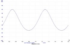
With a 1 ohm resistor on each cathode to ground and a scope you can see the class A and when it switch to class AB
With class A the wave is 360° full, like the attach. The bottom wave is reaching class AB
When it switches to AB one end of each tube became flat
With class A the wave is 360° full, like the attach. The bottom wave is reaching class AB
When it switches to AB one end of each tube became flat
Attachments
In true class A, dissipation goes down with large signal.so as not to exceed 90% dissipation during signal.
At idle, ALL the input power goes off as heat.
At FULL (sine wave) roar, up to half the input power is diverted to the load, so half to the plates.
I had a class A amp on a dummy load, with a very old 6550. It creaked like an old Volkswagen when it warmed up, different when it cooled down. As I drove it from idle to near clipping, it made the cooling-down creak. Checks of DC input and audio output confirmed the plate dissipation dropped from around 39W to about 23W (not quite half, tubes are not perfect).
Think again. If you test with square waves, and if tubes could be perfect switches, the dissipation would go toward zero.
If the goal is HIGH power, class B will get you at least 2.27 times the output for the same dissipation. If you get paid only for Watts Per Bottle, you would always go class B. The tube makers published conditions they thought their buyers were looking for. Sure they would like to sell 2.27 times more tubes in a class A design, but their customers knew better.I have not seen any Class A PP high output power tube designs
Last edited:

- Home
- Amplifiers
- Tubes / Valves
- Class A P-P Output Tube Bias