Effect of harmonics' phase on perceived sound

Hi,

reading documents by Nelson Pass I've seen that most of the people like a negative phase for the 2nd harmonic, explaining it with the fact that it will counteract the inertia of the speaker, but... what about the phase of other harmonics? Need to be as close as possible to zero?

Anyone has direct experience on it or literature to link/attach?

Thank you in advance
Roberto

Hypex Modules NC502MP 2x350W + NC500MP 2x250W brand new.

Hi,

Having abandoned a multi-channel amplifier project, I am selling my Hypex Ncore Module NC502MP


Like new, tested with my DY Project.

  • Free Cables set
  • Shipment to Europe only


Hypex NCore NC502MP twin Channel Module
PSU SMPS integradted 1200W
Nord Switchable RCA-XLR input board
Auto sensing 100-240V mains input operation
0.5W standby operation
1.5KW Main PSU
47K Ohms Input Impedance, low output impedance
THD 0.0018%
S/N Ratio 116dB
26dB Voltage Gain
1X1200W 8 ohms bridged
2 x 350W 8 Ohms
2 x 500W 4 Ohms
2 x 450W 2 Ohms
Fully loaded flat frequency response
92% efficient

Silent transformers for use in preamp

Hello,

I currently have 4 Hammond 229C30 pcb transformers used in the PSU of the line amp. When the preamp is turned on, one can clearly hear the transformers humming.
- These transformers are 24VA each, load for each xfmr is about 10VA.
- See picture of how the assembly looks like. Bottom PCB is mounted to preamp chasssis used damped (rubber) distance holders.
- Downstream of the preamp is a mains filter with DC-blocker installed.

I'm looking for better alternatives than the Hammond 229 series. I've read on this forum that also other users of these 229 series experience mechanical humm.

Dual bobbin is proposed to be ideal in low power equipment, where toroidal's are not due to too good coupling between primary and secundary.

1. Block Low profile - FL series : https://www.block.eu/en_EN/products/transformers/pcb-transformers/
2. Toroidy Supreme audio toroidal: https://sklep.toroidy.pl/en_US/c/Toroidal-transformers-SUPREME-AUDIO-GRADE-V2/99
3. ??? other, better ideas?

Attachments

  • 229C30 assy.JPG
    229C30 assy.JPG
    46.7 KB · Views: 266

How to find any post by only the post number?

The new platform doesn't allow search just by the post #.
I have many posts (links) from the old platform saved by the post #, like:
https://www.diyaudio.com/forums/showthread.php?postid=1206887#post1206887
The links to these posts do not work:
1667578674582.png


Doing this through the "Advanced Search" is very laborious and not always productive. I think there must be an easy way...

DIY Servo driven Linear tonearm

I have been experimenting with LT tonearms over the past 6-8 months, and have built 2 different LTA's with 4 different carriages. During this process I have learnt that a short stiff carriage/armwand is what is needed.

LTA 1 - Built as a proof of concept. This was about as good as my reference arm a Technics EPA100. Bass response was better and noise floor slightly lower. It struggled with stock bearings to track the Stanton 881s so I increased the diameter of the wheels which made a huge difference. Changed to my Technics EPC205mk2 with a Jico SAS.

LTA 2 - This is a total rip off of the Clear Audio TT1 and Niffy's carriage (the FROG). What this does amazingly is lower LP surface noise to levels I have never experienced, detail and dynamics are fabulous. Its issue is tracking off centre pressings where the voice has a lot of energy, I can hear distortion in each channel as the carriage moves back and forth. I built another carriage this time 20g lighter. This new carriage still has distortion on very heavily modulated tracks on the test LP, but I haven't heard it on music yet. It sounds great, but does have higher surface noise.


The reason I started this thread is I am considering building a motor driven LTA and I'm looking for others thoughts and ideas.

Goal is to duplicate LTA 2's FROG performance without the distortion tracking off centre pressings. Is this even possible

First decision is either mechanical servo like the Rabco or use an Adrino robotic controller?

Arm will be split effective mass like the Dynavector DV505. Main arm to be large and rigid with horizontal bearing and secondary arm on the end with vertical pivot.

Technics SL1200 bearings can be used for both pivots.

Carriage will run on 2x 8m linear rails in brass/bronze bushes.

Drive will be toothed belt driven by O rings

Drive motor 12V geared run at lower voltage to keep noise low

Attachments

  • img058.jpg
    img058.jpg
    153.6 KB · Views: 1,045
  • P_20200101_121545.jpg
    P_20200101_121545.jpg
    504.7 KB · Views: 1,098
  • P_20200627_124044.jpg
    P_20200627_124044.jpg
    599.7 KB · Views: 1,021
  • P_20200713_094244.jpg
    P_20200713_094244.jpg
    664.4 KB · Views: 969
  • P_20200616_153223.jpg
    P_20200616_153223.jpg
    470.8 KB · Views: 932

Rockford Fosgate Punch 45HD

I have more broken amps than working amps so it's time to try to fix them. I think this one might be the easiest to fix.

I can't remember what the symptoms were but it started obviously not sounding right. When I picked it up I heard a rattle. I opened it and a tiny cap was loose.

Anyway, on this small board these tiny caps (circled in red) have come off (this isn't my pic but I took it and highlighted the caps, as they are not there on mine).

The contact points on the board don't even look metal. I'm looking for guidance before I try anything because I don't want to screw this up. Can I just try to solder the caps back on? I'm not sure I can even do it, it's so tight in there. Thanks for any input you may have. I'd like to save this amp, if possible.

I went and took a pic of mine and attached it also.

edit: Just ran across a video and learned some new information. That board is the HBPIM board. Any idea where I could get a replacement of that?

Attachments

  • rf_punch45hd1.jpg
    rf_punch45hd1.jpg
    389 KB · Views: 401
  • 20150607_105704.jpg
    20150607_105704.jpg
    485.4 KB · Views: 357

JBL E145 3-way with Audax and "help" up to 100 hz

Have a few pairs of old nice JBL laying around, 2215h, 2235h and E-145.

Also last year have build 6 peerlees xxls 830847 16 ohm in ca 100 liter each in paralel ( 3 each side), now is my stereo set-up.
Thinking of use the JBL E145 as mid-bass from 100-600 hz, and Audax HM130Z0 and Viawave SRT-7 as MTM.

Around 96 dB sensitivity.

Here is my xover in XSIM, anyone seeing something wrong or maby have a easyer way building the xover ?
JBL project.png


Best regards Jawen

48pcs Miller & Kreisel 17500 8Ω silk dome tweeters

I bought these probably 15 years ago for a line array project that never happened. Don't even remember what I paid for them. I think they were "working pulls", but they all look new except for some with misshapen gaskets on the back that just need massaging.

Some of these have recently sold on ebay for $26 a pair + postage. I don't want anything near that for them.

Make me an offer for the whole lot, US only.

Attachments

  • MK1.JPG
    MK1.JPG
    507.3 KB · Views: 153
  • MK2.JPG
    MK2.JPG
    650.1 KB · Views: 154

For Sale JVC RC-EZ51 (Shigaclone Donor) Complete with Remote - UK collection

A spare RC-EZ51 I did not use.
It was bought second-hand so has a few scrapes, but I just gave it a spin and all appears to be working (except cassette!) including the remote.

I don't want to extract the CD player parts as I did this to a previous one & it stopped working for some reason!

Asking a modest £15 for this, so someone local (Northants area) to collect would be ideal.

JVC RC-EZ51_Img1.jpg

FS SE 6.1K OPT Transformer Monolith Magnetics S15 new pair! perfect for tubes 45,PX4,2A3,AD1...

hi all, Selling the following:

- pair of SE 6.1K OPT Transformer Monolith Magnetics S15. Both transformers are heavy duty and new.

Version: Hi-B grain-oriented FeSi dual C-core, air gap for 55mA. perfect for tubes like 45,PX4,2A3,AD1....

Datasheet: https://www.monolithmagnetics.com/s...70 single ended output transformer prelim.pdf

Items are located in Germany and will ship in EU.

--850€-- shipping included

payment via paypal (pay for friends) or bank transfer

Attachments

  • 1.JPG
    1.JPG
    569.1 KB · Views: 161
  • 2.JPG
    2.JPG
    587.8 KB · Views: 176
  • 3.JPG
    3.JPG
    367.4 KB · Views: 193
  • 4.JPG
    4.JPG
    374.6 KB · Views: 192
  • 5.JPG
    5.JPG
    379.2 KB · Views: 177

Ian Canada Station PI with Power Management

Hello everyone,

I am currently running a Raspberry Pi with a Stereo Audiophonics ES 9038 DAC. The power comes from an Audiophonics power supply and is routed to the Raspberry via an Audiophonics power management module. This makes it possible to safely switch on and shut down the Raspberry like an ATX switch on a PC. The music is output to the speakers via a Marantz SR 8015 (dual mono). Now I would like to build a new device and have ordered the parts described in the picture. The power management module controls the raspberry via the GPIO pins 04, 17 and 22. Is it possible to do this when the raspberry is installed on the station Pi, e.g. via the GPIO bar J2 of the FifoPI.

Thanks in advance for your help.

Greetings from Bonn, Germany

Bodenplatte 2-page-001 (2).jpg

Shunt regulator design: shunt VS load current rule of thump

Hello,

Don't seem to find much info on this.

I'm currently using shunt regulators (in combination with serie regulators) as PSU for my preamp. As the dissipation is too high for me to feel comfortable I was wondering to maybe leave this out. According to LTspice, it has no added value in suppresion below 1Khz.
Shunt current is 75ma, load current is 160mA (with max ripple of 2mA).

As I have 4 of these shunt regulators, it saves me more than 8W on dissipation.

What is a good rule of thump of the factor between shunt and load current, to have decent added value of the shunt regulator?

Any references to read?

Thanks
Ben

Attachments

  • PRE PSU.JPG
    PRE PSU.JPG
    126.9 KB · Views: 271

What happens when you run a driver at it’s resonance frequency

So can people please advise on the implications of running a driver be it woofer or mid or tweeter or compression driver at its resonant frequency


Just trying to learn further and understand so a few questions please

A driver Driven at its resonant frequency give or take +/-

1 Can or will damage be expected provided it receives low voltage and not overdriven in excess

2 if the driver been driven encounters higher dB feedback will an amplifier compensate re damping..?.

3 same question as number 1 and number 2 ..but if it was a compression driver would things be different as compression drivers can go low but with higher sensitivity ie 106db vs 85db etc

So in a nutshell can a sustained frequency be amplified without redress.

There’s got to be advantages or disadvantages of doing this thoughts please

4 Can the resonant frequency of any driver be found without parameters ie frequency sweep multimeter

YAMAHA B1 AMP 2SK77

HEY I got one of thoses old/rare YAMAHA B1 stereo natural sound amplifiers that I may want to get rid of. Of course the red overprotection light comes on and no sound comes out but the METERS sure are pretty (yes the UC-1 unit). It handled a lot of great gigs at all the big places in Hollywood back in the 70's....sound incredible and VERY QUITE when it comes to noise.
I'm about to take it over to the local YAMAHA wiz and see if he can find the problem or at least tell me if the VFETS ARE good.
Any help out there?

Something cool for Raspberry Pi/ODROID: I2S/DSD isolator HAT with native DSD decoder

IsolatorPi,something cool for Raspberry Pi/ODROID: I2S/DSD isolator with DoP decoder

I designed a Raspberry Pi I2S adapter a couple of month ago and shared many PCBs for free with this DIY community. http://www.diyaudio.com/forums/digi...mate-weapon-fight-jitter-371.html#post4429205
It was really nice. Community members and I were very happy with it. But I’m still worried about sharing noisy PC ground with audio system.

Another thing is that I'm very interested in playing native DSD music through Raspberry Pi. I’ve heard that the latest version of MPD already has native DSD support. But after downloading the software, I was very disappointed to find that the native DSD is only supported over USB interface. This has also been confirmed by Tim. It means the native DSD feature works only with a USB streamer for now. However that's not the way I use a PRi.

And the third thing is the ODROID. I bought a C1+ because a friend of mine recommended. It has a dedicated I2S port (which is incompatible with PRi). It also runs faster than RPi. I'm quite happy with it. The only issue is that none of the RPi audio gears will work with ODROID because of that I2S port.

So I came up with a new idea: An I2S/DSD isolator HAT with optional native DSD decoder for Raspberry Pi and ODROID.

It will have following functions:

1. To isolate ground and all other signals between RPi/ODROID and audio system.

2. Compatible with both RPi and OROID.

3. Supports native DSD playback by plugging in an optional DSD decoder daughter board. The daughter board will convert DoP stream back into native DSD stream bit-perfect at real-time. In this case, all current SD image such as Volumio, MoodeAudio, RuneAudio, and most others, will have native DSD play-back features.

4. Raspberry Pi DACs and other audio gears will work with ODROID (may need software support for configuration).

5. Has isolated I2C control bus for RPi DACs, as well as optional I2C EEPROM ID bus. It will work very well with all RPi DACs and other audio gears by flowing Raspberry Pi HAT design specification.

Since I'm working on multi-channel I2S/DSD FIFO PCB, hopefully I can place a bulk order.

Here is the block diagram. I will be finishing up this project soon.

Ian

IsolatorPiBlockDiagram
by Ian, on Flickr

A very simple "RONIN" amplifier

I want to offer you such an amplifier As a good replacement for the 3886 and 7293 microchips, which have become much more expensive. instead of 240/9240, you can use a very cheap 510/9510. In a differential cascade with a different correction, bipolar transistors can also be used, as cheaper and more accessible. In general, the spice model is below, pdf with a diagram and a *.Ley for ordering or reworking for yourself.
PS ^ I really want to know your opinion, it is dear to me.

Attachments

Mismatch between trafos- acceptable?

So i built a gainclone monoblocks with same exact everything between two units but one channel was humming through the speaker while the other was dead quiet. It turned out to be magnetic coupling of the trafo which i was able to solve by slowly rotating the trafo and my ear to the speaker until the hum went away. The trafos are vigortronix todoidal.
Heres where my gripe starts. As a test i also began rotating the trafo on the other channel and it too had a position where it could induce hum to the amp. But that position differs between trafos by about 40 degrees! Which means the windings between the two units are uneven, even tho they are of the same model and was bought together.

Are such deviations in their windings acceptable?

Displayport out to HDMI in for multichannel audio

Hi there,

So far I have been experimenting using EqAPO as a multichannel loudspeaker crossover on a laptop with HDMI out to a Marantz 7.1 Receiver with HDMI in. The laptop is aging, and could fall apart any day now. It looks asif more PC's and laptops use Displayport out instead of HDMI.
Could Displayport out also be used for 7.1 -filtered- audio channels out, or do I need some convertor?

Goldmund Studietto with T5 arm manual on hifiengine

Someone can download the manual for the Golmund Studietto with T5 arm for me on vinylengine please ?
I can no longer access my account or open another one on their site.
I have just recovered this vinyl turntable literally in pieces that a former customer bought on the internet and the seller sent the turntable as is without clamping it or securing it, so I will try to rebuild it, starting with the arm and the belt.
thank you in advance

A digital audio stream feeding 'almost' directly a Class-D driver & output stage?

Note to Readers: (added on the 31st, Oct 2022)
Please note, this thread should be considered as a discussion only. As it evolved it cannot give working ideas as to how to implement completely digital drives for Class-D.
--------------------------------------------

I do not know whether someone has already done this, but logically and technically, it seems possible.

Suppost a digital stream similar to that used to drive DACs is fed to an algorithm running on a microcontroller or small processor. The algorithm would use extrapolation to calculate the value of the instantaneous voltage at points which are not covered by the data from the stream. These calculated values/data would then be used to calculate the pulse width to feed the driver of the output stage. This would still result in an audio output, but without a DAC.

Learning Bookshelf+Subwoofer Pros and cons ?

Hi all,
comparatively ready 3 way speaker choices are limited (either expensive or one has to buy floorstander) So I was wondering...
1) what are technical disadvantages of having a bookshelf with subwoofer ?
2) If bookshelf measurements are available, can a passive crossover be made to match that bookshelf speaker with DIY passive subwoofer ?
3) (vague question) I know it depends on driver, speaker design and personal volume level preference, but what is very broad consensus on a typical 8 inch driver low end extension and levels achievable ?
thanks and regards.

MMats Hifi-6150D blown MOSFETs

Hello, I'm new here and this is the first amp I will try to fix. I have SMD soldering and development experience but this is my first time working on an amplifier. Here we have an MMats 6150D, it was working fine before but it let the magic smoke at random once. I opened it up and noticed this:

Clearly, a MOSFET died
SYdw0EG.jpg


I took out the clamps and noticed that 80% of the MOSFETS cracked or burnt on this rank of fets alone, all the other MOSFETS around the amp seem fine.
GIfR4rc.jpg


I cleaned out the smoke residue and noticed two resistors blew, I checked the diodes and they test out fine still. I also noticed the temperature sensor (?) on the upper left has its leads burnt, but I think that is due to the MOSFET nearby producing heat.
J2yal8P.jpg


So now to gather parts, as I understand when a MOSFET gives out, it takes its driver IC with it but I don't know which one is it
wi33D9I.jpg

QsmEARdl.jpg

QOviYvol.jpg

b2qEnYkl.jpg

ndI3GCjl.jpg

Yc1O2ojl.jpg


Questions:
  1. What's the best MOSFET to use? burnt ones are really faded out but I managed to make out "top line: IRF3205, middle line: I&R P12J, bottom line: 40 CZ"
  2. What resistors should I use? -markings have been burned out, the only clue I have is a nearby one that is the same physical size with margins "10RD" (or 10R0), everyother resistor is a smaller in physical size.
  3. What driver IC can I use?
  4. Anything else I'm missing before I go out and buy parts?
I want to try and fix this myself as MMats charges $250 to get this done, but if i must I will.

Thanks!

Troubleshooting PSB Gold i “quad amping”…

I finished to build 2 pairs of monoblocks (Dynaco MK3s from scratch with VTA boards). The amps do sound great! But I ran into an issue when attempting to biamp each speakers: i removed the jumpers between the speakers posts and wired one monoblock to the tweeter/mids and another one to the woofer. Turned the first one on, all good. But when I turned on the other connected to the woofer, I got a squeal which moves up in pitch as more current reach the output tubes.

Same thing happened with the other speaker. I triple checked everything, it’s not coming from the amps or the speaker cables. With only one amp connected to the woofer (nothing connected to the mid/tweeter), same result. If I put the jumper back on between the posts, everything is fine.

I did test the speakers with the jumper removed and no wires attached: on the woofer posts, I read 4 or 5 ohms and there is continuity while I can’t get a reading between the m/t posts (and there is no continuity). If I wire an amp to the m/t posts, then (and only then) I get a reading of 4 or 5 ohms. So I guess the issue is in the crossover… any idea what it could be and how to fix it? I found some threads online where people did biamp these speakers, so I guess it’s possible But since I’m using monoblocks, could this be the problem?

Some suggestions would be much appreciated!

Horns and waveguides 101

I saw a number of recent threads asking some pretty fundamental questions about horns and waveguides and how the various types differ.

The following is my attempt to provide some guidance.

There are fundamentally SIX types of horns that you can use, and they all have their pro’s and con’s.


1) VERY old school symmetrical round or square exponential/hypex horns. Examples of these would be the early WE ones and the ones still used in those Japanese Goto, Ale, etc. Installations. These horns (i) load the drivers well down to the horn’s cutoff, and (ii) equalize the compression driver’s natural high-frequency mass-induced roll-off at the high frequencies, resulting in pretty flat on axis, but they beam a lot. They also lead to some pretty serious reflections at the mouth, unless they are either used only above 2-3x cutoff, and/or are improved with some suitable additional round-over at the mouth. The axi-symmetric JMLC horns fall into this camp, and they are arguably the best at addressing the mouth reflection issue.

2) Old school exponential/hypex radial horns. Examples of these would be the old Altec “sectoral” horns, like the 511 and 811, or the Fostex radials (H420, H320, H220, H400, H300, etc.). These still achieve the same (i) and (ii) feats above, but they manage to also yield almost constant directivity on the Horizontal plane over much of their bandwidth (at the expense of vertical coverage, which is monotonically decreasing and even narrower overall). The more “classic” radials also have some issues with internal reflections and diffraction, because of the abrupt profile discontinuity at the throat. But, these latter issues can be mitigated by clever design improvements, as done in the Yuichi Arai horns, as well as in several other similar Japanese wooden horns like those by Yamamoto, Ta-On, GT Sound, etc. I PERSONALLY CONSIDER THESE TO BE THE BEST OVERALL COMPROMISE FOR HOME HI-FI, but of course I’m aware that it’s all a matter of picking one’s favourite trade-offs, and that others may disagree, and for very valid reasons.

3) Tractrix horns. These tend to be very similar to n. 1), but with reduced mouth reflections, and poorer driver loading towards the lower end of their bandwidth. The main problem I have with these is that the theory on which they are based is very shaky. In simple terms, the tractrix profile “looks” nice but there is no sound physical justification for it whatsoever. So I don’t consider it a very credible contender, especially given that the JMLC horns (see 1) tend to solve the same issues and offer improved loading.

4) Conical horns. These are essentially simple “funnels” with straight walls that simply constrain the driver’s radiation into a solid angle of choice. There are two BIG problems with them, though: (i) they do NOT load the drivers effectively at all, resulting in very poor low frequency extension even in the case of very large horns, and (ii) they present the worst possible abrupt discontinuities at the throat and at the mouth, resulting in awful reflections and diffraction. In other words, in my humble opinion, why bother?

5) Modern “constant directivity” horns. JBL and Altec were the first to develop these in the 70s/early 80s, with the aim of ensuring a more homogenous coverage of the venues served by PA systems in Pro sound applications. The main problem with these early efforts was that the profile was decomposed into two sections: a very short expo/hypex throat section, expanding in only one dimension, and feeding a second conical section through a diffraction slot. While this achieved the desired constant directivity, while also giving marginally better loading than a simple conical horn, there were serious drawbacks in terms of (i) diffraction, and (ii) still poor loading nonetheless. The JBL 2385 is a typical example of these horns. All the later JBL horns use in their home products such as the K2 S9800, S9900, etc. still essentially belong to this camp, but they backtracked a little on the diffraction slot, smoothening it to reduce the severity of the effect, and in so doing also giving up a bit of directivity control...

6) Even more modern “constant directivity” waveguides. These are the result of a radical re-thinking of the purpose of having horns in the first place. Basically, their rationale is that today power is cheap and we don’t really need efficiency and loading any more; all we should aim for is directivity control, AND the least possible amounts of diffraction. The best examples of these are Earl Geddes’ OS waveguides. They are essentially conical over most of their expansion, but with an ideal, mathematically-derived throat section that transitions from the planar wavefronts at the compression driver exit to the spherical wavefronts within the conical part of the waveguide. Loading is still very poor, but at least they are (very) good at something, I.e. diffraction minimization. To me, if you buy into the argument that directivity control is essentially all that matters, these are a much better proposition than the “constant directivity” designs at point 5) above.

So, there you have it. As I said many times already... pick your poison! ��

Marco

Tubes selection for SET output

I probably want to try to build a vacuum tube amplifier in nearby future. Let it be a medium powered (15-20W) SET amp. A significant part of existing designs is based on something like 300B or 2A3 which are just too expensive. I live in Eastern Europe where Soviet made tubes are readily available so I can search there. 6c33c is the obvious option. But what about more "classic" tubes like direct heated triodes? There is GM70 which is reasonably priced too but it means spending more on transformers. What other options do I have? With transistors for comparison it's quite simple, you have catalogs with parameters to choose from. Also they are more or less similar to each other in the same power handling group (especially BJTs and to a lesser degree FETs). But tubes... I'm just getting lost.

Magnat Traxx 660 no sound

I have this old amplifier that needed a bit of work.
The sound output was a bit crunchy on one channel and there was a of lot cold solder joints.
I decided to refresh it and make it reliable for everyday use so I resoldered cold joints and replaced all electrolyte capacitors

The problem is that the amp after resoldering does not play. There is no protection led, but I think it's in protection mode.
After that I replaced
- TL494
- TL072 (instead of ba4558)
- IRFZ44 as per schematic instead of 50n06 that were originally on the board
- rectifiers
- TIP41 and 42
Both BA4558N are ok, sound goes to the R153. After I think that is grounded as there is 1.12v on the pin 1 of the U1 optocoupler.
There is 1.8v measured between the supply ground and signal ground.
Square wave is ok, but the rail voltages are a different: +33.3v and -29.5v. 16v voltages are +16.6 are -13.6v.
Input voltage is 12v.
Output transistors are ok, 1n4148 diodes are ok. I checked many resistors and they are within the spec. There is no voltage on speaker terminals.

Here's the schematic diagram https://elektrotanya.com/magnat_traxx_660_sch.pdf/download.html

What should I do next?

What type of bypass caps for a DSP (adau1466)

Hi,

I study a PCB for a DSP adau1466 from Analog Device.

The datasheet proposes a layout implementation diagram as shown on page 200 of its datasheet. The layout diagram is attached.

A lot of capacitors are BYPASS caps and I would like to know what is the best type to use: MLCC ? Film (what type) ?

Thank you for your reply

Attachments

  • Layout implementation.JPG
    Layout implementation.JPG
    89.5 KB · Views: 103

Amphion Bases DIY project

Hi, I am going to be making a pair of Amphion Bases type stereo subs (photo attached), to use with my Amphion One15s, and would like to ask you folks some questions:

1. I am going to be using Seas 10" drivers and passive radiators, there are to options, one with two layers (L26ROY) and one with four layers (L26RO4Y)
Which one would you recommend for this application?


2. I will probably be using two Hypex Fusionamps plate amps, going to choose between FA251 and FA501.
Which would you choose? is 250 watts enough for a single 10" in a large box, working all day with the subs behind the desk? or should I go for 500 watts? won´t need lots of SPL


3. Regarding Fusionamp DSP crossover, I want to integrate the One15s and the subs with the crossovers, but be able to bypass the subs and use the One15s in full range mode.
Is this easy to do with the software? I think you can´t control both amps at the same time, so it would be cumbersome to change the usb cable when going full range?


That´s all for now, thanks everybody!

Attachments

  • DSCF1013.jpg
    DSCF1013.jpg
    272.9 KB · Views: 143

Genuine Toshiba 2sk170 BL - Matched Octet

TL,DR: matched octet of 2sk170 BL grade Transistors - € 50,- each octet + shipping costs - 30 slots available - GB closes on Sept. 30th. (or when 30 sets are gone) - items will be shipped between November and December

ships to U.S.A. and Canada using seaways, will take 30day plus, but is tracked, signed for and insured

Hey everyone,

the last group buy went pretty good, maybe too good because i did not have enough devices left after i shipped all the octets. Thats the main reason for the second round of this group buy. Some things will be different then last time. I will match 30 octets out of 600 devices, so matching will be tighter then before.

I will buy the stuff from the last known source for original Toshiba 2sk170 parts in sealed bags of 200 pieces in the whole wide world.
Buying in the US does come with some downsides. I will have to pay import tax and customs fees. Thats why the cost for a tight matched set of 8 transistors will be € 50,- plus shipping.

As I am located in Germany, shipping costs will be cheaper if you live in the EU rather then the US. I want to avoid shipping overseas due to corona troubles (US, NZ, AU) but i will do it at your own risk (international letter, tracked and signed for, no insurance possible, € 8,50).
Shipping costs for Europe are € 8,50 (DHL small parcel XS, tracked, signed for, insurance up to a worth of € 50,-)

I will buy three sealed bags of 200 transistors each and match them for Idss and Vp using this method.

I use to sort the values using a spreadsheet to get the best possible sets of matched jfets. I have some experience with this method and I know that it will produce reliable results.

When all 30 slots are gone I will ask you for payment. After payment i will order the transistors. It will take 10 to 14 days for them to reach me and some free weekends for me to match all those devices. After matching, all orders will be shipped as soon as possible.

You will get 2sk170 from the BL Range – so Idss could vary between 6 mA and 12 mA. But if you give me a hint which Idss range you need I will try to solve it.

Any questions: please ask.
Add your name to the group buy like this:

NAME QTY COUNTRY
AddiDub 1 Germany

Attachments

  • matching-jig.png
    matching-jig.png
    83.3 KB · Views: 1,718
  • s-l1600.jpg
    s-l1600.jpg
    153.2 KB · Views: 1,717

PS-x600 speed issue

Hello all, I recently got a Sony PS-x600 turntable.
Everything works except it has a lot of WOW ( unstable rotation speed) - it is very audible.
I checked the speed with my phone, and I got an average reading of 33,33 which is ok but the speed oscilates a lot.

I got the service manual and checked the quick measuring points, one being the speed sensor and the values are in limit ( around 30mV). I cleaned the speed adjustment pots and got no improvement. I measured all the caps around the power supply section and they are like new, I measured the diodes around the power section and they also read good.

What I find strange is that there should be +30V and -30V supplied to the motor control board, but I read -27V and +26V with the motor off. The +15V and -15V rail both measure 14,6V so I guess those 2 are ok.
But if I run the motor the +30V rail drops to around +22V with fluctuation and -30V rail drops to around -25V also with fluctuations - which I'm guessing is not ok and could cause the speed issue?

Also is it possible to measure the motor windings if they are ok?

Any help or ideas would be very welcome!

port area and driver Sd

There is something that I wish to understand.
The svs pb16 has 3 3.5" round ports which comes out to a cross area of 186.2cm^2
I don't know the sd of its 16" driver.
For a 15" driver like sw115-4 has an sd of 855 so the port area vs sd is 21%.
Would the svs pb16 chuffed at low frequency high spl? Would it need around 1/3? May be the 16" has a ridiculous sd?

Attachments

  • svs pb16.JPG
    svs pb16.JPG
    35.4 KB · Views: 103

Alpair 10p vs MAOP-10

I now have my 10p enABL2 based Halcyon speakers working well and sounding pretty good. I do sense a bit of congestion when played loud in the upper end, which is dominated by the 10P. Mind you, they sound very good, and are pleasant to listen to. However, I wondering if the MAOP-10 or the metal 10m would solve my issues? I listen mostly to classical, Jazz, vocals, etc. No rock.

The extra cost of the MAOP-10 is not an issue as I have spent way more in the cabinets and crossovers (and the amp and dacs to drive them) then the costs of the original 10p driver by several times. I will have these speakers for a long time and am curious to know if I can squeeze the last bit of performance by the MAOP-10s. With the Halcyon Design, bass is not the issue as the bass duty it handled by a pair of SB acoustic woofers on summed transmission lines.

It is the mids and high end I hope to improve. I would appreciate any insight from anyone on the forum.

-david BTW

Buy or DIY PA style speakers to go with NX3000 & sub

1st thread so hello to all. Apologies in advance, i don't often post in forums so will try my best!

So as title, I want a pair of PA style speakers that will be mounted in two corners close to ceiling. They will be used for Karaoke, DJ sessions and small parties in a 62m3 room. I am hoping to make use of a spare NX3000 amp I have to power them and I also have a twin 10" DIY sub low passed @ 100hz, also powered by an NX3000. The sub is hooked up to my 5.1 Diamond 220 setup, Pioneer LX73 Receiver and does more than I need, for now!

Buy or DIY? Simpler to buy but from my experience always better and more satisfying to build.
Things to consider. Although no expert, i have basic wood working skills and tools such as, table saw, plunge saw, router etc and have already had a go at building 2 different sub boxes, so I feel comfortable enough to build myself and want to learn more anyway.

I've been looking over the "so you want to design your own speakers from scratch" thread and have taken notes on "determining basic needs". I will be honest a lot of it went over my head or may not apply to my situation. I am hoping that by answering them question here along with some notes, I could get some advice and recommendations.

Basic needs....
Space is not really an issue, the two corners are free to make use of, within reason of course.
How Loud? Based on the following i would say pretty loud lol. 1 : We already know what amp will be used, it is rated at 2 x 900w @ 4ohm or 2 x 1500w @ 2ohms so I will have plenty of power. 2 : They will be used in a party/dj environment and i already have a really good sub to back them up.

We listen to lots of fast paced dance music so need something that responds well. We will be using for karaoke (SM58) lol and listen to plenty of vocal music so we want something that's going to make vocals sound nice and bright. In this case i would say we were after something the opposite of flat speakers.

Boxes, as mentioned I will be building so no cost to consider other then materials, that I still have here and there 😉 They will be mounted and I need to work out how I am going to do that. One question here is do I need/want ports? From my understanding, loosely, a ported box take less power going down low vs sealed that requires more power but result is clearer bass tones. Although, seeing as I have a ported sub that's filling the room nicely and an amp with plenty of power ready, it makes me wonder if i am better off going with a sealed enclosure on this occasion as its more the clarity and detail i want from them anyway. Thoughts on this appreciated.

Tools, The one thing i may need here is "measuring equipment". I've got all the woodworking covered, I have a windows PC but what equipment do I need to start me off? I presume at the minimum a special microphone.

Crossover, At present I need to look into this a bit more. Designing on computer will be one thing but testing will be another. I am leaning towards passive crossover however.

Budget, 250 - 350 but maybe able to stretch a bit. This would be for speakers and crossover parts only. No labour cost and I'm not including the wood cost either, I have lots left over and its cheap for me around here.

Speaker type, 2 way and I'm thinking 12 to 15" driver unless 2 x smaller would be better for more detail in the midrange? I always see horns in PA speakers and this made my mind jump to them automatically. However I would appreciate any recommendations for my application, in the meantime I will be researching tweeter types as I have never, until now need to buy any.

Sorry if a long read guys 🙁 again I don't often post and have problems sometimes explaining myself.

I've looked over some really good guides and found some awesome material but unfortunately most of what I'm finding is related to 2 way or 3 way full range designs and mentions about adding a sub afterwards.
My situation is i have the sub covered first and i feel maybe wasting money and time buying speakers designed for sub 80hz and tuning the boxes as low as they go etc. When in fact the money and time maybe better spent!
I feel I don't know enough yet to make a better choice and the more I google around for drivers and start comparing spec/prices it all get a bit overwhelming tbh!

I am terrible with words and only hope that this makes sense. This is an ongoing project so I will be indeed researching as I go but appreciate any kind words you guys have to share 🙂

JLCPCB 3D Printing

Apparently JLCPCB has a 3D printing service now. Prices seem pretty low, and they're able to print some pretty big parts.

Only challenge is that when I try to upload the .STL file for the augerpro waveguide, the units are wrong with no obvious way to change it.

Anyone used this service or have an idea how to work around this? Their PCB fabrication is usually pretty painless and reliable, so I'm interested to see how their 3D printing capabilities are.

If it's cheap enough, this could be a huge deal.

Sansui AU-717

I have a Sansui AU-717 integrated that I bought new with paper route money in the mid-70’s (I’m 63 now). It’s in excellent condition and I still have the owners manual…wish I’d saved the box. The amp works perfectly but I suspect is overdue for caps/bias adjustment, cleaning, etc. The cover has never been off.

I do not have the knowledge or skill to attempt it myself. Looking for quality service recommendations ideally in the Atlanta area. I prefer not to ship it if possible. Appreciate any guidance.

-Mike (first post on DIY)
1EC0A572-DC27-47C3-B131-E8BF09A51C40.jpeg

Tips on how to create a chassis (sample image inside)

Thinking of something like this (see below)

But in my case
  • the front fascia is made of wood
  • the top, bottom and rear are made of aluminum plates
  • 2 heatsinks attached to an aluminum plate make up each of the side
  • L brackets to attach each piece to each other

Feedback? Perhaps you have a better idea?

thanks in advance

Screenshot_20220914-221830_AliExpress~2.jpg
  • Like
Reactions: dliscomb

I don't know what to believe (Basta vs manuf data)

I'm trying to pick a bass driver for a "micro-Manzinita" and I can't make heads or tails of the data I'm getting from the manufacturer vs out of Basta. I'm looking at the Goldwood GW-212/4 (1.2 Qts, black on the charts) & 12PC-4 (~0.4 Qts, red on the charts).

Here's the manuf data overlaid (in a 10 cu ft box):
1666994582844.png


Here's Basta data in a big box:
1666994627392.png


And here's Basta data on the 0.5x0.5m open baffle I'm planning (I will high pass around 200Hz or so):
1666994757243.png


What am I missing about the manufacturer's data? I will prob just get the GW-212/4 and call it a day.

Altec 605B / Onken / Duelund

For sale:
A pair of Altec 605B speakers in Onken 360l cabinets with Duelund CAST crossover.

2x Altec 605B coaxiale drivers with AlNiCo magnets and Markus Klug wooden horns (original horns included). 97dB/1W/1m
2x Onken 360l cabinets in Nantex
2x crossovers with Duelund CAST capacitors and coils, Pathaudio resistors, ETI research speaker posts.
2x Duelund CAST inductor 2.2mH
2x Duelund CAST PP 20uF + 0,01uf silver bypass capacitor
2x Duelund CAST Copper 12uF
2x Duelund CAST Copper 1uF
4x PathAudio resistors All cabling (crossover+internal) Duelund DCA16GA

High efficient speaker set, that's equally at home in small and larger rooms.

SOLD

Attachments

  • IMG_3041.jpeg
    IMG_3041.jpeg
    337.5 KB · Views: 273
  • IMG_3042.jpeg
    IMG_3042.jpeg
    283.3 KB · Views: 234
  • IMG_3043.jpeg
    IMG_3043.jpeg
    263.1 KB · Views: 257
  • IMG_3044.jpeg
    IMG_3044.jpeg
    284.7 KB · Views: 195
  • IMG_3045.jpeg
    IMG_3045.jpeg
    381.8 KB · Views: 207

Goldwood brand speakers

Has anyone heard of Goldwood brand speakers? They appear in the PartsExpress catalog, and they were the only 4 ohm 5.25" speakers that I could find. They also sell for 8.95 so I'm skeptical, but if they can sound good in a car, I'm willing to buy them, if anyone has experience with it. At Madisound I've found 4 ohm Vifa speakers, that come at a heftier $57 per speaker, and also a $27 speaker. Any input on which one I should rather buy for a car audio setup? Am I looking for woofers, or midrange, or midbass? Not midbass I believe, and I will match these with a tweeter. How would I setup a crossover network for example how do I know how many Farads/Voltage for the capacitor I will need to use? I noticed that they usually cut the midrange? at around 3500 Hz. I'm trying to build a diy car audio setup. Any input is appreciated.

Millett NuHybrid Headphone Amp Mods

After building and listening to the Nelson Pass B1 Korg preamp and comparing it to the Pete Millett's Nutube Buffer preamp, I found I liked the sound of Nelson's Korg tube setup a bit better. I figured out how to make Pete's Buffer sound more like Nelson's B1 Korg and then it was onward to the NuHybrid headphone amp.

Not obvious is that all 3 circuit designs invert the signal. This happens at the NuTube itself. This is easy to correct with loudspeakers by reversing the loudspeaker/amplifier connection wiring but not easy with headphones unless you want to take them apart and rewire them. Listening tests confirmed that I preferred the correct polarity with loudspeakers, so I decided to try adding input transformers with reversed primaries to the NuHybrid to correct that circuit and see how it sounded. i did not want output transformers since the circuit was going to be driving headphones, not a high impedance.

I first experimented with some inexpensive Triad TY-250P transformers I had had kicking around just for evaluation purposes. Imaging was very much improved but their lack of shielding, excessive phase shift in the low bass and higher THD proved unacceptable. I ended up purchasing and installing a pair of Jensen JT-11P-1 1:1 high quality line input transformers and installing them with the primary winding connections reversed.

Here is what I did to modify the NuHybrid Headphone amp to compensate for the polarity inversion and to have it sound more like the Pass B1 Korg. The build was done in a DIYaudio Galaxy chassis with all jacks, power switch, LED and volume pot mounted off the PCB and on the chassis panels.

1. The Jensen input leads are configured as unshielded twisted pairs connected directly to the isolated RCA input jacks. Input polarity is reversed with respect to the transformer output. The RCA jack shells (grounds) are tied together and connected to circuit ground to eliminate hum when a source is connected. The output leads of the transformers are configured as unshielded twisted pairs and connected directly to the volume pot inputs. The transformer can shields and internal electrostatic shields are connected to circuit ground at the input side of the board. I provided a direct chassis ground connection at that point a with the series resistor/cap to chassis ground connection shown in the Jensen data sheet. A dedicated ground wire was run from the volume pot ground terminals to circuit ground at the input side of the board. Since I was using a 10K pot, the Jensen data sheet damping network was not required. Even though my pot is an Alps RK27, it has excessive noise at the extreme CCW rotation, which seems to be a problem with 10K pots in general. If I end up changing it to something like a 50K, I'll add the recommended damping network.

2. I bypassed the on-board PCB volume pot connections altogether and went straight from the pot to some slightly larger Kemet 220 nF input caps that were then connected to the PCB at the C20 and C21 locations. Shielded coax connections from the pot to the caps input sides are grounded only at the PCB end.

3. I changed the NuTube plate resistors R13 and R14 to 332K.

4. I set the plate voltage at TP1 and TP2 to about +9.75 volts. I found this is best adjusted while listening to music and set to your preference. I also found that anything over +10.5 volts made the magic go away.

So how does it sound? With the resistor and plate voltage mods, I think it sounds better than the stock 475K plate resistors with voltage set closer to half-supply. Smoother, with no loss of dynamics or detail. Correcting the signal polarity with the transformers made a very significant improvement in detail and imaging. Yes, they cost as much as the PCB, tube and board components combined but once you hear the difference, there is no going back.

Attachments

  • NuHybrid Mods front.jpg
    NuHybrid Mods front.jpg
    573 KB · Views: 568
  • NuHybrid Mods top.jpg
    NuHybrid Mods top.jpg
    315.6 KB · Views: 541
  • NH HPA Mods schematic.pdf
    NH HPA Mods schematic.pdf
    38.4 KB · Views: 280

Simple Linear CRCRC PSU

I have two versions of these available. The first is a single rail positive PSU and the second is a dual rail PSU providing positive and negative outputs.

I have done a full write up on the single rail board here.

The single rail PSU is ideal for building into enclosures as stand alone power supplies for headphone amps, DACs and pre-amps.

The dual rail PSU is good for building projects that require both a positive and negative supply which you can house all together in the same enclosure. For example I have had a lot of interest in this board for use with Wayne Colburns BA2018 Linestage amp which is quite fitting as after all these PSUs are based in part on the Whammy PSU. I will do a full write up on my site once I get more boards from the fab house hopefully with the correct silkscreen and no lines. 🙂

I did my own measurements too with the scope to verify the boards I made are just as effective as Wayne's original design and the readings speak for themselves.

And for anyone that says "why are you using those old noisy regulators?" I added a smoothing cap on the output of the regulator and measured the output with the scope and I can confirm the ripple is just as straight as it is on the 3rd cap in the main filter.

Excuse the lines on the dual rail PCB the fab house messed up somehow with the silkscreen when trying to draw the caps on.

I have plenty of boards so if you are interested then drop me a PM. 🙂

Attachments

  • IMG_20200404_003130-1382x1843__01.jpg
    IMG_20200404_003130-1382x1843__01.jpg
    703.2 KB · Views: 948
  • Screenshot_20200319-211052__01__01__01.jpg
    Screenshot_20200319-211052__01__01__01.jpg
    325.4 KB · Views: 902
  • 11204355.jpg
    11204355.jpg
    76 KB · Views: 918
  • 11204356.jpg
    11204356.jpg
    77.4 KB · Views: 926
  • PIC B.jpg
    PIC B.jpg
    503.2 KB · Views: 886
  • Screenshot_20200418-153525__01.jpg
    Screenshot_20200418-153525__01.jpg
    636.8 KB · Views: 512

Using the GRS PT5010 (Neo10 clone) as a dipole midrange

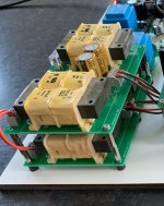
It looks like GRS has picked up the technology of the B&G Neo line of planar drivers and Parts Express is now selling them. This is a great time to revisit what you might make out of this line of drivers. Here are some thoughts about how to best use the largest member of the lineup as a dipole midrange.

I've always wanted to get my hands on the Neo10 but never quite did, but have just ordered a pair of the GRS PT5010. It seems to be an almost exact clone, at least visually. I took a look at the response plot that GRS provides in the datasheet to get some clues about how I can best use this driver. I like to build dipole loudspeakers, and the PT5010 can potentially work as a midrange. I assume the response that GRS is providing in the datasheet is with infinite baffle loading:
880140d1601498313-using-grs-pt5020-neo10-clone-dipole-midrange-grs-pt5010-mfg-datasheet-response-png

I was hoping to cross over to it around 700 to 800 Hz, but the response is starting to sag there, with the SPL dropping down to under 90dB/W (the driver is rated at a nominal 94dB@2.83V).


To get a sense of what I might expect in a baffle of anything from zero (nude) to as large as I want to go I used the Edge to simulate some responses at a few angle up to 45deg off axis. I thought I would share what I found, which I think is indicative of how many drivers in planar baffles will behave as you vary the baffle size. Keep in mind that this is only the response of the baffle - you have to add it to what the response of the driver will be, e.g. its nearfield response. For that I will use the MFG curve for now until I can measure it myself.

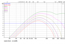
First, let's look at the "no baffle" or "nude" response. It looks like this:
880136d1601498313-using-grs-pt5020-neo10-clone-dipole-midrange-response-baffle-png

This has a very smooth response. The curves all follow each other, with only a bit of narrowing above 1.5 to 2k Hz. I would call this "CD like". There is very little sign of a classic "dipole peak". But since the low frequencies start to roll off just about 1kHz using the driver like this would only add to the downsloping response based on the MFG data.

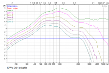
OK, since I was planning to build a "slim" dipole system, how would the driver look in my narrow baffle? I tried out a 36" high, 10" wide baffle with the top edge of the driver at the top edge of the baffle. This what that looks like:
880137d1601498313-using-grs-pt5020-neo10-clone-dipole-midrange-10x36-baffled-response-png

We can see that even this slim baffle has changed the response quite a bit. Now the response has a broad hump in it, centered around 1kHz. The result is that the response below that point has been brought up by a few dB. This would help to offset the losses from the driver in that region. OK, good so far.

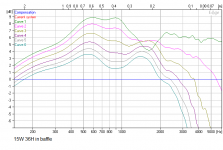
Maybe we can do some of that same thing, but more of it, by using a wider baffle. Let's try going up to 15" W with the same baffle height and top-center driver position. Here is what that looks like:
880138d1601498313-using-grs-pt5020-neo10-clone-dipole-midrange-15x36-baffled-response-png

Indeed, the response down to 500Hz has been brought up a bit more. But there is a new feature - a pinching and even crossing of some of the responses around 1.7kHz. This is exactly what you get when you use a baffle that is more than about twice the width of a driver and has been pretty well documented. It's not desirable to have this kind of response feature, because there is no way to correct for it in the crossover. This happened just by increasing the baffle width by a few more inches!

In fact, if you move the driver location to smack in the middle (horizontally and vertically centered) of the baffle, you will almost always get this kind of behavior:
880139d1601498313-using-grs-pt5020-neo10-clone-dipole-midrange-15x36-baffled-response-driver-centered-png

Now the low frequency is well supported by the baffle, but the trouble spot remains, here at around 1.5kHz. It would be fine for a woofer but not for a midrange. This is why I feel that many wide baffle OB systems have built in problems. For instance the classic woofer plus fullranger in a large baffle - it is building in response issues that you cannot get rid of. Some of the Pure Audio Project systems come to mind, for example.

Usually I aim to implement a driver with as little a baffle as possible. As a result, some of my speaker systems are just drivers hung by wires. But that insures the driver responses are as smooth and CD like as possible.

But for this large planar driver it seems that the 10" wide baffle will work great. I hope to use it with a pair of 8" woofers below and a planar tweeter (probably the new GRS one) above, probably nude. It will also be visually "thin" which is helpful for dipole systems because the baffle will not block or interfere with the rear output, which you want to be able to let though so it can form that wonderful open soundstage that a good dipole system is known for.

Attachments

  • response for no baffle.png
    response for no baffle.png
    22.5 KB · Views: 4,460
  • 10x36 baffled response.png
    10x36 baffled response.png
    18.5 KB · Views: 4,308
  • 15x36 baffled response.png
    15x36 baffled response.png
    18.7 KB · Views: 4,319
  • 15x36 baffled response - driver centered.png
    15x36 baffled response - driver centered.png
    18.4 KB · Views: 4,225
  • GRS PT5010 MFG datasheet response.png
    GRS PT5010 MFG datasheet response.png
    38.4 KB · Views: 4,842
  • Like
Reactions: Haze Head

  • Locked
For Sale Citronic SM550 DJ mixer

This device was sent to me to fit a power supply and test basic functionality. However the owner pulled out and left the device.

It sure needs a revision which I won’t do as I don’t have a use for it.

It has a good reputation apparently. For the handy person that wants a classic mixer and is not afraid to do some work.

Only shipping within the EU. Offer me a price via PM if you want it.

Attachments

  • 10D28C18-D709-47C8-B187-84B86B164ADC.jpeg
    10D28C18-D709-47C8-B187-84B86B164ADC.jpeg
    596.9 KB · Views: 143

Yet Another Analogue Line Mixer

Gentlemen

since a long time I am looking for a small mixer suiting my needs: 2 Stereo Channel input, 2 Stereo channel output which are easily switchable. The requirement came from the fact that I often do A-B tests, either comparing 2 sources to one amp, or one source to two amps to compare amps. It is not for DJ use.
As I did not find something which totally suits, I tried to come up with my own design.

  • Sliders pots for the input and the output
  • good sound performance
  • small form factor
  • Analogue-like VU meters using an Arduino and two small OLED
  • Possibility to have a Bluetooth receiver connected, having a rotary volume and which can be switched off using a switch
  • two clip leds, also powered by the arduino nano.
  • All parts on the PCB

The "software side" is under control, but I am not really an expert in hardware design. Is there an expert who could take a look on the schematics ? Are there any major bugs ?
As a small thanks I would offer two PCB's to the one who could help.

I designed the schematics in EASYEDA Pro, the PCB is not routed yet but the places of the potentiometers, input rca jacks, vu meter is kind of "given".

Inputs will be highly appreciated.
All the best,
Christoph

Attachments

  • SCH_2_Channel_Stereo_Mixer_OLED_0-Design+1_2022-11-03.png
    SCH_2_Channel_Stereo_Mixer_OLED_0-Design+1_2022-11-03.png
    38.6 KB · Views: 149

Concept 16.5 Issues.

Good day all,

I have a Concept 16.5,

Great old receiver, I love it. Recently a problem has been occurring. The volume can be at ANY level, low, medium, or loud. All of a sudden I get a quick and very loud buzzing sound over the speakers(less than 1 second long). The receiver then kicks into protection right away, then it kicks back out of protection mode(maybe 3-4 seconds it sits in protection) and continues to play the tunes like nothing has ever happened. Other than this the receiver has absolutely no background noise or hum, the bass is so tight and defined it's unreal, this receiver makes an old set of 30 watt hitachi's sound like gold.

I made sure all connections, grounds etc are tight inside, ridded of the dust, quadruple checked my speaker connections etc.

So does anyone have any insight as to why this might be happening? Some extra info before I bring it down to the repair shop would be great.

Also any info on Concept gear in canada? i'm in Northern Ontario, had never seen any Concept gear until I found the 16.5, which would have went to the dump the very next day. Been enjoying it for a while.

Sometimes the problem occurs after a day, sometimes it takes 1-2 weeks to happen....

Thanks and have a great day!

Restoration of an old Pioneer SA-9100 amp questions

Hi Folks.

Could you help me with some information please. I have a Pioneer SA-9100 amplifier bought and kept by me since 1973. It needs work to restore it to better performance.
I am in Canada (east coast) and I would like your recommendations on who does this kind of restoration work here, and their reputation.

I don't know what is the proper place to post this, so please excuse me and move it to the proper thread if need be.
Sincere thanks in advance.
Randolph

Semi prices, revisited

As if there was any doubt about price gouging and the ongoing speculations (rather than inventory crisis), here's an infuriating example:

Two months apart, Dec 2021 vs. Feb. 2022, while the semi "crisis" is ongoing. An about 228% price increase. This is from DigiKey and Mouser, not AliBaba or EBay.

Attachments

  • dec2021.jpg
    dec2021.jpg
    23.3 KB · Views: 199
  • feb2022.jpg
    feb2022.jpg
    30.2 KB · Views: 207
  • feb2022-mouser.jpg
    feb2022-mouser.jpg
    36.2 KB · Views: 201

Distributed mode panel speakers "DML"

Interested in dml flat panel speakers. Have found alot of information and practical realistic design builds. Amplifydyi for ex. Bought an exciter 40 watt a Parts Express for under $30 total. Great company. Have been experimenting a bit with different materials and size. Attachment is also a big concern for unfunded vibration. One design attached the actual back of the excitor to a solid surface and had bad results. These panels I am using 1" pink foam board 2x2 feet hink poly styrene. Really vibrate visually and quite violently. Like long excursion sub woofer. I am thinking about using magnets to suspend panels via electromagnetic force so the vibrate ith out physical attachment. Any suggestions or input I would appreciate. I used springs and rubber bands. No test equipment so not sure if connection design is that important. Will try and combine a longer panel with smaller one for better bass. 2 excitors on one panel doesn't seem to work for videos. Trying a damaged dome tweeter with attached different small panels. No success yet at all..Any crazy out of the box ideas would be appreciated and maybe tried out. There is alot to his design that needs to be explorer. Michael

WHAMMY Build Questions

Hi,

I am brand new to this forum. Please let me know if I'm violating any rules. I'm in the middle of my WHAMMY build and I am stalled due to missing/incorrect parts. I sent an email of to the diyaudiostore customer support.

In the meantime it seemed like the opportune time to ask a few questions about the build. I am building the stock version of the kit. Mine came with the AMVECO 12.5 VA + 12.5 VA/18 V + 18V transformer. I am using the red LEDs in the power supply section for reference voltage.

1) My op amp is labeled 458,000 JRC A133 A. I can't find the data sheet for it. Should I be using the optional 22uF/25V caps at C26 and C27 or should I jumper those pads? My understanding is that if this op amp is bipolar, I should use the caps.

2) In the build guide the shielded cable used for inputs/outputs has the shield connected at both ends....at the jacks and at the pcb. In all the preamps I have built I was advised to connect the shield at the jacks, but not at the pcb. Doing so, I was told, could induce ground loop hum. What should I be doing here?

3) I've read all the threads about wiring the panel mounted LED, but I'm still confused. A clear 5mm LED was supplied with my kit. Given the transformer I have at what specific pads on the pcb should the anode and cathode be attached? What value resistor should I attach in series with the anode? If after attaching the resistor I wish to lessen the brightness of the LED I could increase the size of the resistor, correct?

Thanks in advance,

John

Attachments

  • 09B5E976-2C21-4CAE-B211-B416C296FE75.jpeg
    09B5E976-2C21-4CAE-B211-B416C296FE75.jpeg
    510.5 KB · Views: 141
  • 5853BC73-DCD7-4F74-99DB-A4304B5F8385.jpeg
    5853BC73-DCD7-4F74-99DB-A4304B5F8385.jpeg
    425.4 KB · Views: 134

Adjusting capacitor values in this portion of the circuit, will it have a negative affect?

Hello all, I have a Mackie M1400i power amp that was having many issues that have mostly been resolved, but found some rail voltage where it shouldn’t have been and it was due to a faulty 270pF silver mica.

F7896B8A-322C-43D2-9E6E-FBB5F96241EA.png


So I plan to replace both C18 and C20 in both channels. What I have on hand are 330pF silver mica and 220pF and 330pF in both polypropylene and ceramic, not sure if dielectric matters here. Ultimately I’d like to swap in four 330pF silver micas, but want to make sure that increasing 60pF won’t cause an issue. I’m trying to save the $25-$30 I’d have to spend for four new silver mica and shipping costs.

Should I be okay with the 330pF mica or would be better to go down to a 220pF poly or ceramic?

Thank you,
Dan
Projects by fanatics, for fanatics
Get answers and advice for everyone wanting to learn the art of audio.
Join the Community
507,619
Members
7,880,061
Messages

Filter

Forum Statistics

Threads
405,869
Messages
7,880,061
Members
507,619
Latest member
Yahweh1x