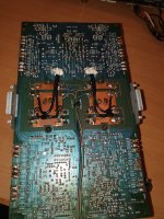
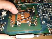
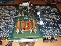
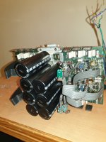
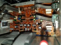
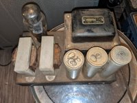
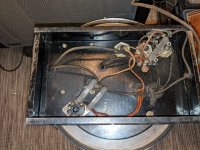
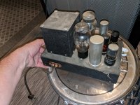
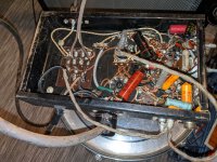
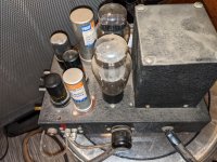
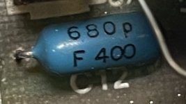
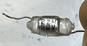
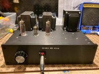
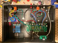
Been through a number of iterations on developing a power amp for my stereo rig - most recently, a few months back I had a thread for a stereo SE amp built around the 807. I got as far as a crude prototype, but life intervened again. In the meantime, I found an eBay auction for an inexpensive pair of Hammond AO-39 chasses. These were reverb amps for the A100 organ, and have a 5U4-based power supply, two 6BQ5s in cathode-biased AB1, and a 12AX7. Hmmmmmm ... a pair of PP monoblocks with a little more power ... Hell yeah, I'm in!
The original circuit is built around a differential input, and is not really appropriate for a guitar power amp in a number of ways, so I designed a circuit with a Fender-esque LTP on the input and adjustable cathode bias for the power tubes. I chose to use the 6P14P-EV in order to run higher voltages (and dissipation, but as we'll see that wasn't an issue), and the 6N2P on the front end because I have a pile of them and I'd rather use my vintage ones in something where they'll make a difference.
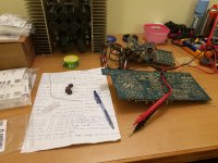
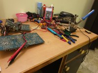
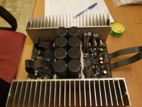
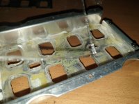
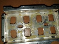
I've successfully built the prototype, and am now stripping the chasses to prep for cleaning and painting. I may or may not reuse the noval sockets, depending on how easily they clean up (and whether I break them in the process).
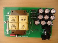
Power Supply
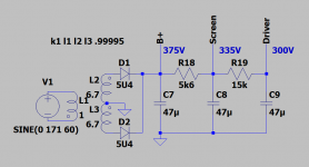
The original power supply ran the rectifier into a dropping resistor and then to a CRC pi filter, taking the B+ from the second filter cap. This is overly complicated for my use case, so I simplified it to taking the B+ from the first filter cap. Removing 250R and using modern wall voltage raised B+ by 55V, to 370V, well within spec for these tubes. I chose 335V for the screen supply based on simulation results, and the the PI is fed a solid 300V. The 6.3V heaters will be elevated from the power tube cathodes. The 5U4 is running well within spec.
 Phase Inverter
The PI is a standard Fender LTP. I think I cribbed the values from the Deluxe Reverb? Simulation showed that the 82/100 plate resistors were overcorrecting for the imbalance, so I changed to 91/100 and got very close. I think I also changed up the GNFB values.
There will be a 100k attenuator prior to the blocking cap.
Power Section
Bog-standard shared cathode bias EL84 power section. The only complication I added is a 2W 200R pot so that I can dial in the bias more closely when I change tubes. The pot goes to a 100R resistor to ground for bias measurement. I also added a 100K resistor around the pot for insurance - if the pot ever fails short, this will cut the tubes off instead of letting the bias get too hot. 470R screen resistors simulated the best balance between output and distortion. Oh, and I also built the simulation with a 16R load on an 8R transformer, because the Hammond OT wants a 4R load and I'll be using 8R cabs.
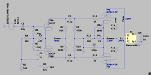
The only disappointment I've got is that due to the GNFB, it's got pretty low sensitivity. I may use a pot for it to be able to adjust sensitivity on the fly. OTOH, I'm also using a preamp that can easily drive the low sensitivity if necessary.
Specs:
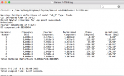
5.4Vpp (1.9 Vrms, +8dbu) input yields 11W at 1% THD
7.6Vpp (2.7Vrms, +10.8dbu) input yields 14W at 5% THD (just getting into crossover distortion)
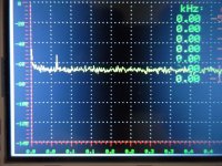
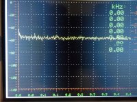
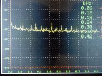
Frequency response +/- 1dB from 40Hz to 33kHz (limited by OT - the circuit simulates at +/- 0.5dB from 10Hz to 77kHz)
Output impedance ~1R in the audio range
Plate dissipation at idle: 12W
Screen dissipation at max output (14W/5%THD): 2W
I'll be posting pictures as I go to show how things are progressing. Would love to hear any thoughts on the circuit or the approach!
