Vintage V-FET Amps - Why So Little Interest These Days?

I've been wondering this for quite a while now and I'm hoping someone can help me with an answer. Why is there such little interest these days in these amps? I have a Yamaha B-2 and I'm always amazed at how wonderful it sounds; such depth and detail in the sonics.

V-FET's make so much sense as audio amplifying devices and except for Nelson Pass no one else seems to be too interested in them. Can anybody tell me why that is please?. :scratch2:

Two Matched pairs of 2SK180D

Quad matched 2SK180D, pictures and curves.
400 euros.
Also I have quad matched THF51S and 18 more, not matched but tried and with very linear curves.
Send a PM
Thanks in advance
Esteban Bikic

Attachments

  • Like
Reactions: Rodeodave

Output Transformer Proximity... Can they be too close together?

I'm just about to dive in on an EL34 push-pull amplifier build and am curious to know if the left and right output transformers (OTs) can be TOO close together. I found a schematic and notes in an MJ magazine I picked up in Japan and it specified a chassis size that is unavailable. I've got something close, but in order to get the OTs far enough away from the power transformer (PT) I've drawn them up as being about 5mm apart. Does the forum see any issue with this? Cross talk etc.?

Also, in this position do they seem far enough away from the PT?

I've attached a drawing of what I'm planning with relevant dimensions.

Thanks in advance!

Screen Shot 2022-11-30 at 7.11.37 PM.png

Amplifier selector

I'm not sure where to post this as I think it's one of a kind. Let me know or move it where it should be posted.
I've searched for a while and could not find a selector that lets one set of speakers and one line level input source, (pre-amp...ect) be the source for, as this one was built, up to "4" two channel amplifiers. I built it so I could hear differences between two channel amplifiers that I've built without having to connect and disconnect them every time. It's straight forward and easy to build. I jump connections across the negative speaker terminals. I used the 5v selection from the line level control board to feed and control the speaker board. Again I jumped the 5v input of the speaker board to select two at a time instead of one. Please Modify to your liking.
Hear is a list of materials.
Scott

HiLetgo 5V 8 Channel Relay Module with OPTO-Isolated Support High and Low Level Trigger​

DIY Switching Board 4 Way Signal Selector Amplifier Relay Audio Input Switch Module​

Banana Plugs for Speaker Wire (6 Pairs, 12 Pieces), 4mm Pin Plug Screw Type, 24K Gold Plated Connectors Insulated (Support 12 AWG to 20 AWG Wires) Two sets...​

RCA M/M Stereo Audio Cable... As many as you need.​

MEAN WELL RS-15-5 AC to DC Power Supply Single Output, 5V 3 Amp 15W​

HiFi DIY Audio amp chassis / table top enclosure / Instrument Case 20-12123N from Pi Metal Products Inc.

Other items are stand-offs, screws...ect.
1.JPG
1.JPG3.JPG4.JPG5.JPG6.JPG7.JPG9.JPG8.JPG7.JPG6.JPG

1.JPG

Attachments

  • 2.JPG
    2.JPG
    828.3 KB · Views: 220

Behringer Ultra-Dyne 9024, new..

Behringer Ultra-Dyne 9024, new..

"Vintage" stereo studio processor, new, never used, in original packing. Interesting component, from processing to sound equalizing/ analyzing. Also convertible to 8024 with cheap and simple Eprom exchange.

https://www.enjoythemusic.com/magazine/equipment/0101/behringer8024.htm


As said, really NOS, new, packed, never used.

Price 100€ plus shipping. (22€ EU Countries..)

Regards
b1.JPG
b2.JPG

PA guitar amp conversion - could use some insight on mystery tube amp

I’ve been looking for a PA amp to convert into a 1x12 combo guitar cab for a couple of months now, and finally found what appears to be an ideal candidate for a conversion.

70E738CA-ADB5-4B20-856F-77974695E04E.jpeg


This amp was made by Viking of Minneapolis, and the model number is PA-93.
The specs: 12AX7+12AU7 preamp tubes, 12AX7 PI, push-pull EL84 output. Actual wattage is unknown, since I can’t find a single mention of this amp anywhere, except for a brief video on YouTube that wasn’t very informative. Viking of Minneapolis was well-known for their reel-to-reel decks, but apparently not their tube amps. The PT and OT are beefy, but small, so I’m expecting this to likely be in the 13 watt range.

The controls on the front appear to be a rotary on/off switch on the left, tone, then two volume controls for the 1/4” mic input on the front and the rear phono input. The pot all the way to the left appears to be a bias adjustment of some kind. Maybe hum cancellation?

Here’s the gut shot.
15438C32-7979-4C14-8078-ECD74BC094E9.jpeg

All the date codes point to a manufacturing year of 1960. The latest code I’ve seen is the 36th week, on that cap just to the right of center. It has diode rectification, though I haven’t been able to identify those either. The diodes have “IR” on one side with a diode symbol in between, and the other side says “66” and right below it says “4241.”

Here’s some other close up shots of the interior.

12AX7 input:
741C5863-D00E-49EF-9EA2-B66021276FB9.jpeg


12AU7 second stage:

95FAB5B1-7F7A-4127-B75A-34A77EC6E6F8.jpeg


12AX7 PI:

CD4F5CCC-16AE-477A-9E2E-89D1FB4F7656.jpeg


EL84 power tubes:

BD4BE16F-127E-4041-ADC5-7D0FDE317C98.jpeg


The blue wire coming off the 8ohm OT tap here appears to be negative feedback of some kind. It connects to the resistor on the terminal strip and then back to the 12AU7. The OT has 70V, 8 ohm and 4 ohm taps:

0C7FB6AA-1878-47C7-A67A-6B4C01F667A3.jpeg


The kinda cool part is this came complete with tubes of unknown origin, and they ended up being a Telefunken 12AX7 on the input, and a pair of Mullard rX1 B0K EL84 power tubes, complete with soot. The other two tubes were just an RCA and a Sylvania, nothing special:

312ABA9D-993C-415C-B7D4-B42D545A59EE.jpeg


I’m not sure what state they’re in, since I don’t have a tube tester, but needless to say I’m buying replacement tubes to use while testing the circuitry, lol. Preliminary checks so far are very promising. The resistors haven’t drifted out of spec on all that I’ve measured, and even the caps all test good, which was the biggest surprise so far. We’ll have to see what happens when they get a few hundred volts through them.

I’ll probably end up having to trace out a schematic myself, but I was hoping somebody might know something more about Viking of Minneapolis, or about any other amp that used this circuit, that might point me in the right direction. Some of these old manufacturers are really tough to find info on.

Thanks!

Question on frequency vs age vs design.

Lets assume Im the only guy who will ever listen to this system.
Or lets say its just me and my buddies who are all in the same age group i.e. 55-70
Ive been reading up on how the human ear changes with age and so decided to do some tests. We found that all the people over the age off 55 could not hear anything over 14,000 Hz. Where as the kids and grand kids had no problem hearing even 18,000 Hz. Or more.
Samsung have this tech in their phones called Adapt sound. Where it plays a series of tones and based on your age and what your ears can pickup it creates a profile. The profile boosts all points past the point you can hear. The music does sound better. But if you do a freq test. You still cant hear the freqs past a certain point.
My quandry is
a. Do I build my system to just ignore all freq past 14K because thats all me and my buddies can hear.
or
b. Do I build a system that works like adapt sound which boosts freq above 14K
I know its a kinda pointless question. Which is why Ive stuck it in the everything else forum. But would still like you inputs.

Repurposing Hypex FA123 components

Background

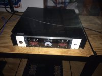
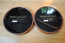
I have a pair of FA123s that I no longer use. One of them has an issue I can have Hypex address, but I have another thought.

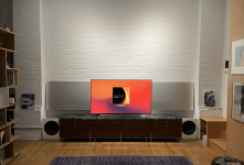
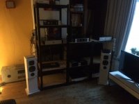
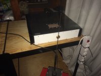
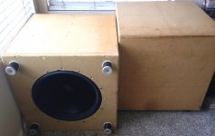
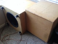
I'd like to repurpose the components of the FA123s in support of extending my home theater audio system (see attached image).

I have two stereo NCore amps that I use with a miniDSP device to integrate DML panels and woofers that serve as left and right front speakers.
I have additionally turned my LG OLED TV into a center channel speaker by attaching an exciter to it.
I have smaller DML speakers to serve as rear left & right channel speakers.

I have an A/V pre-processor that has the capacity to do the room equalization I may need.

I need amplifiers for the smaller DML rear left & right speakers and the center channel speaker.

I can use the working FA123 for the center channel, but this seems too much of a device for the purpose.
Additionally, as I would use RCA analogue out from the A/V pre-processor to the FA123, the FA123 would first do an ADC (analogue to digital conversion) make the digital available for DSP, then apply its DAC to return analogue output to the center channel speaker.

The FA123 does much more than I need.

This said, the FA123s's NCore amps - on their own - could prove a great match for my application.

Question

Could I repurpose any of the components of these FA123s?

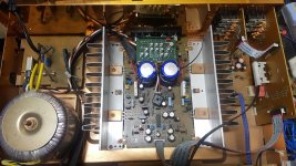
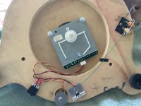
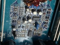
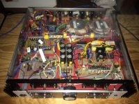
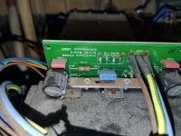
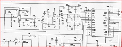
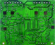
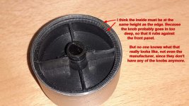
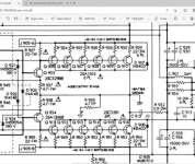
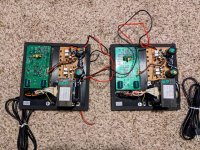
I could have all the following wrong (see attached image) ...
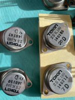
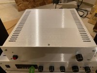
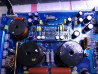
The 100w amp appears to sit on a discreet board and receives power from the power supply mounted on the board holding the two 125w amps.
I don't need the DSP | DAC functionality.

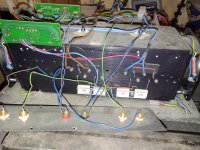
Would the following work for the center channel amp?
  • RCA analogue inputs.
  • Binding posts for speaker wire.
  • Add an appropriate power supply for the 100w amp.
  • Supply mains connection.
  • Put in in a box.
The question then becomes whether I can do something similar for the rear right & left channel, but using the 125w amps and bypassing DSP | DAC.

I know I can purchase 2 or there UcD180HG with HxR from Hypex and put something together, but I really don't need 180 watts per channel.

These FA123s have served me very well across a number of different systems, I'd love to give them another life.

Any thoughts appreciated.

Attachments

  • Screenshot 2022-11-27 at 1.17.10 PM.png
    Screenshot 2022-11-27 at 1.17.10 PM.png
    1.4 MB · Views: 158
  • Screenshot 2022-12-01 at 4.44.32 PM.png
    Screenshot 2022-12-01 at 4.44.32 PM.png
    359.5 KB · Views: 163
  • Screenshot 2022-11-30 at 10.24.49 AM.png
    Screenshot 2022-11-30 at 10.24.49 AM.png
    1.6 MB · Views: 145

"ESSentielle" MHP DIY Speakers ESS Heil AMT3 / Satori Egyptian papyrus

Hi amigos,

Let me introduce my new DIY floor speakers (2.5 way) based on the "ESSentielle ADS" diagram of "la maison du haut parleur" (MHP)
The cabinetmaking is made of French Ash wood with a vertical grain. (25mm) cabinet size 100x28x30CM
These speakers are based on the famous ESS Heil AMT 3 Tweeter (latest generation) and two Satori MW16PNW-8 Woofers in Egyptian Papyrus whose measurements are here:

http://www.loudspeakerdatabase.com/SB/MW16P#8Ω

The Crossover has been the subject of a 2 year R&D with a gain adjustment, it is manufactured by the "Maison du Haut Parleur" in Toulouse, still in France. It has been specially developed to get the best out of the ESS Heil AMT3 Tweeter.
This Crossover is mounted with discrete SMD type components. The Woofer part is filtered at 6DB / octave with two Jantzen Selfs (Grade 1B copper wire @ 3% / 0.10 Ω) with a very low DCR.
Here are the cutoff frequencies:

385HZ/1700HZ.

Bass Woofer can go down to 32HZ @ +-3DB
I wouldn't be very objective if I gave my opinion, would I?))) But I'm in love with Heil AMT3 Tweeters and I must admit that the first time I listened to these speakers, I took a real slap!
The Satori Woofers seem to marry very well with the ESS Tweeter, the listening is musical, detailed and of a beautiful straightness.

For ESS fans : you can listen to the DIY kit in Paris / Toulouse and in Lyon if you are ever passing through) They are available in a version with a different cabinetry and less elegant than my DIY version but listening and electronics remain the same.

Here the review of the Heil ESS AMT3 Tweeters :

https://www.tnt-audio.com/casse/ess_amt_e.html

And here are the pictures 🙂


  • Thank You
Reactions: GM

  • Locked
New IRS rules for Paypal, Etsy, Venmo (etc) vendors and gig workers

The IRS has just issued a rule which will require companies like Paypal to issue a 1099K if your gross sales in any calendar year exceed $600. Previously a $20,000 PLUS more than 200 transactions was the threshold.

This even means if you have a garage sale, sell at a hamfest, or via your webstore the receipts will be recorded as "income" and you will probably have to file a1040 Schedule C (or some such).

Keep good records of your expenses!

Question on tube substitution

I've become enamored of dual-dissimilar triodes recently; spud amps just seem like fun to me. I've built a 6T9 and ECL82 and ECL86 amps.

I recently saw a nice-looking schematic for a 6CY7, a Novar base tube intended for television use originally.

6CY7 Single-Ended Hi-Fi Stereo Amplifier

I happen to have some NOS 6FY7, which are compactron tubes intended for the same purpose as the 6CY7. I looked at the tube data sheets and they don't seem to be very different from each other.

http://www.nj7p.org/Tubes/PDFs/Frank/093-GE/6CY7.pdf

http://www.nj7p.org/Tubes/PDFs/Frank/123-GE/6FY7.pdf

The main difference seems to be the plate dissipation for the output segment:

6CY7: 5.5 watts
6FY7: 7.0 watts

So other than the possibility of more output power, I don't seem to see much different. But I am a newbie. Am I missing something important here?

Thanks!

Mcintosh MAC 4100 bias adjust

I have a MAC 4100 that I am trying to adjust bias on. I read the SM instructions for the procedure but would like to know precisely where I should be clipping my meter leads to to read the AC line current. I tried to read across the fuse holder with the fuse installed, but that only read 7 mA on my Fluke meter. Without the fuse installed the speaker relay would not energize. Mcintosh experts help would be greatly appreciated.

Recapping/modding yamaha m916 console HELP

Recently got an m916 which im using for tracking to a tascam trs-8 and summing. planning on recapping at least 8 channels and the master channel. Been reading through a groupdiy forum of a recap on the same board but all of the schematics with cap value changes and mods are no longer online.


I already have some JRC 5532D's and opa2604's on the way for opamps

also thinking of modding the eq

Any info or mod ideas will be very appreciate

For Sale Triplett 3423 Emission Tube Tester Working But May Need TLC

This is a pretty nice Triplett 3423 Tube tester which I've acquired many years ago. It's a very decent tube tester that tests Emission, Shorts, Gas, Leakage; etc.

In case you don't know, the 3423 is the 2nd best lineup of tubes' emission tester Triplett ever made while 3444 being the top of the line big brother to the 3423!

I've not used this in many years because I am now using Hickok Cardmatic Tube tester. It is working but may need some service and recalibration for daily use. I don't know for sure since it is vintage item and sold as is.

While I was using it, it is very fairly accurate tube tester. I've replaced some electrolytic caps and some tubes inside this many years ago as precautionary measure. I also installed inline fuses on both live and natural side of the AC power cord.

I've just tested it with both 45 tube and the 12AU7 tubes just now and the test results seem to agree with my Cardmatic tester.

The tube test chart rolls nicely from the start of the chart to the end without any problem and it's in very nice condition.

Having said that, there are some minor known issues that may require some Total Loving Care (TLC)!. Line Adjustment is a little flaky occasionally but powering it ON or OFF or flipping the Tube Strength lever a couple of times seems to clear that up. I think it may need some cleaning on these mechanical parts or some caps or components may need attention which I don't know or not have time to look further. Or it may simply needs some calibration! The acorn socket may need replacement but who uses them anyway?

It comes with reprinted user manual, additional tube supplement chart, calibration guide, circuit diagrams, and a very rare Triplett Tube Tolerance Computer Chart which is pretty neat!

The tube tester looks very good and mint internally but the outer case shows age!

It costs a whooping $199 in the 60s but I am asking $400 firm for this nice tester.

This tester weights almost 20lbs unpacked!

Paypal fees and shipping fees will be added based on your location.
+
20220807_134557.jpg


20220807_134620.jpg


20220807_134440.jpg
20220807_134557.jpg
20220807_134620.jpg
20220807_134440.jpg
20220807_134122.jpg
20220807_134114.jpg
20220807_133700.jpg
20220807_133618.jpg
20220807_133615.jpg
20220807_133413.jpg
20220807_133343.jpg
20220807_133331.jpg
  • Like
Reactions: yogiDIYbear

FS: free diy turntable w/purchase of new(open box) AT-VM95ML cartridge

Turntable is built from a vintage Onkyo CP1015a, using the direct drive motor, carbon fiber tonearm and rubber feet.
Remote 19vdc power supply included.
no transformer!
33-1/3 rpm with pitch adjustment.
anti skate.
strictly manual operation
Solid mdf base.
ADC headshell.
Cartridge was installed briefly to evaluate with Shure Era lll test record.
Sounds great. Compared to Dual, Thorens, Technics and Linn.
I‘m moving house and can’t take it with me.
$169 plus shipping from 30047

Attachments

  • AEBFD94E-5A54-4977-AE32-8F3202123E51.jpeg
    AEBFD94E-5A54-4977-AE32-8F3202123E51.jpeg
    486.6 KB · Views: 233
  • 2507E0EB-67F2-4536-B55F-5559B9377A71.jpeg
    2507E0EB-67F2-4536-B55F-5559B9377A71.jpeg
    661.3 KB · Views: 228
  • BA8C0C59-2E69-45FC-BBAC-0838281C17FC.jpeg
    BA8C0C59-2E69-45FC-BBAC-0838281C17FC.jpeg
    518.9 KB · Views: 226
  • A0C79ACB-F1AE-4A35-8D42-C923F23DFCBA.jpeg
    A0C79ACB-F1AE-4A35-8D42-C923F23DFCBA.jpeg
    496.2 KB · Views: 233
  • 7A7070D9-0E86-40B1-AC44-6368453367D5.jpeg
    7A7070D9-0E86-40B1-AC44-6368453367D5.jpeg
    623.8 KB · Views: 225
  • 52AB3895-0F86-4F39-AB23-B38D57DC8E06.jpeg
    52AB3895-0F86-4F39-AB23-B38D57DC8E06.jpeg
    546.4 KB · Views: 220
  • 7B0382FF-DC5A-4C62-A121-D4413BA5F54E.jpeg
    7B0382FF-DC5A-4C62-A121-D4413BA5F54E.jpeg
    397.7 KB · Views: 221
  • C77DF131-B794-4772-9F50-FACF93072E6B.jpeg
    C77DF131-B794-4772-9F50-FACF93072E6B.jpeg
    456.1 KB · Views: 229

How to connect Van Den Hul The Integration Hybird

Hello,

i am trying to build my first 2x1m cable VDH The Integration Hybrid cable to connect my PrePhono to my amplifier.

I have just received 2m of this cable. The connectors are RCA.

The cable has: 2x brown wires, 2x white wires, 1 metal braid.

So, looking for (good) advice how to connects the 4 inner cables and the metal braid to the RCA male connectors.

Please, do someone really knows how to finish this cable ?

Many thanks
Luca
Italy

Hifonics Clycops XI

Hello my Friends.Can anybody help me?This Monoblock amplifier has somtimes high frequency noise from the subwoofer.But work is fine!
I made a video from this.
DLM4500 board i can measure the +-15V/60V and TL072D(DL102),LM319(DL101) has +-9V.

Login to view embedded media

Attachments

McIntosh MC 2105 Isues

I could use some help thinking through an issue. A couple of years ago I recapped this unit and it was operating to spec. After a while the right channel meter stopped working and later the right channel started losing output power. At the time I was busy and didn't really need the amp, so I put it on the shelf until now.

Here's the current situation: At the head phone jack, with no load, there is 29 vac rms on both channels. H'ever at the speaker outputs, with 8ohms dummy load,, left channel is OK, but right channel is distorted and won't create power. From the Power Output Section schematic, it seems that there is likely something wrong with/at the right channel OPT.

Does thing make sense? And, if so, ideas on how to proceed would be sincerely appreciated.

Seeking advice for reconfiguring Cerwin Vega D9 15" box

I own a pair of Cerwin Vega D9 with a 15" woofer. I've never been that happy with the mids-highs or the way they are positioned so out everything goes everything... but my woofers.

I am rebuilding a new box with high end dayton and vifa drivers. But since these will sit separate and on top of the woofer box, I need to cut a bit on the height of the woofer box. So I need to cut about 20% on the volume.

The specs on that woofer (152WR) are nowhere to be found so I will have to guess. The stock box has two 10" long X 4" round ports, and the new one will have one 16 3/4" by 2" rectangular port at the bottom. What I can play with is the port length. I do not mind paying with efficiency, these will be bi-amped.

I have ordered a Dayton test microphone, and was thinking of looking at frequency responses with different port lengths.

I am looking for suggestions and ideas on the "how". (Please, not on the "if" or "why").

3 pairs TO-3 amplifier to fit in enclose as photo attachments

Jow members, afther a long time waiting i want to task weither somebody has schematics for a 3 pair MONO amplifier to fit in the enclosure as photos below.

On www.buildaudioamps.com there is this project, except it has not been released yet.

DSCN3018ClassAwidget.jpg

The transistors, 12 in total, are the MJ2955 and the 2N3055


ic+boost-f4.gif


Now i am using this schematic from www.sound-au.com, and of course it works fine.

And have left 1 pair on each amplifier not connected.

In the middle there is the power supply with 2 toroidal transformer it, for a separate 35VDC in total of 340VA power supply. Picture IMG_1081.JPG IMG_1079.JPG

Looking for a higher quality amp, to replace it.

Question: Does anybody know a website for a amplifer schematic to exactly fit in this enclosure ?

If not with 3 pairs on each side, but maybe with 2 ?

Thanks Greets, Wouter van Wegen

woutervanwegen@gmail.com

PS: There are PowerCON cables and XLR cables between the power supply in the middle and the 2 amps. On the left and right side.

Attachments

  • IMG_1073.JPG
    IMG_1073.JPG
    62.4 KB · Views: 232
  • IMG_1075.JPG
    IMG_1075.JPG
    62.4 KB · Views: 208
  • IMG_1078.JPG
    IMG_1078.JPG
    314.2 KB · Views: 200
  • IMG_1079.JPG
    IMG_1079.JPG
    287.5 KB · Views: 215
  • IMG_1081.JPG
    IMG_1081.JPG
    489.1 KB · Views: 240

A blast from the past (2005), The scrapped KSA-50 clone

A friend of mine was cleaning and sorting his garage after moving three times in the last few years and found an old relic.
Instead of recycling it he asked if I wanted it.
When I saw what he had I almost made an Indiana Jones, yelling "it belongs in a museum!"

What he had dug out of the junk pile was a 2005 Pinkmouse Krell KSA-50 clone with a massive 30x2VAC transformer of 1kW and 4x68000uf capacitors TO-3 transistors and a large tunnel heatsink cooled with two 230V fans.

Dusty and dirty as hell and not very well built (if I remember correctly).

Now, this was at least 15 years ago but if I remember correctly around 2x25 VAC and minimum of around 4-500VA was "enough".

If I where to try and put it together and accually use it I need to make some alterations.
I need it smaller and cooler.
So I'm thinking mono blocks.

Cooler means lower rail voltage.

I happen to have two identical transformers but they rate in at 2x18VAC and 200VA each.

So, to get to the point (finally).
Has anyone starved the amp this way? Running it on this much lower voltage and what should I expect?

And what do you think about cooling? It would probably need considerably smaller sinks, right?

Attachments

  • P_20201128_171019.jpg
    P_20201128_171019.jpg
    1 MB · Views: 531
  • P_20201128_171024.jpg
    P_20201128_171024.jpg
    1 MB · Views: 503
  • P_20201128_171033.jpg
    P_20201128_171033.jpg
    1,004.4 KB · Views: 482
  • P_20201128_171046.jpg
    P_20201128_171046.jpg
    979.3 KB · Views: 532

Nad C356BEE won't turn on

Hi!
I have this problem with my Nad amplifier. Yesterday the amplifier was in standby mode and i observed that it's starting to make relay clicks constantly. The relay clicks repeated in 2 seconds interval, the amber power led it's no longer lit, the power button not responding. Disassembling the amplifier i found that the clicking relay is the one on the volume and tone board. Measuring the 5v rail on main board i get 0.4v ascending to 1.8-2v synchronized with the relay clicks. If i disconnect the power supply board from the main board, i get stable 5v on power supply board. Any idea how to find the bad components? Thanks!

Budget Subwoofer

I've been looking at inexpensive subwoofers lately. I was looking at the SVS SB-1000 when they were going for $499 (when the Pro version came out). But I was too slow/cheap to pull the trigger, and now I can only get the SVS SB-1000 Pro now for $100 more and I doubt I'll spring for that.
So now I just saw that Costco has the Klipsch R-W12Si for sale for $189.

According to the Klipsch website, the normal price is $449. But I don't see it selling for that much anywhere.

https://www.klipsch.com/products/r-12swi-wireless-subwoofer

Any chance this is a decent sub? I can't find a real review of it anywhere, probably because it's too econo to be of interest to a real reviewer.

Anybody have one? Or think it might be worth the $189 at least?

Eric

What woofer required for .34 cuft. enclosure

I am looking to replace the drivers in an old pair of Phase Tech PC-60 II speakers. The original 6.5 in 4 ohm (styrofoam cone) woofers are gone but everything else is original and mint. Sealed box .35 cuft., nice 4th order Linkwitz-Riley crosses over at 2000khz. Any suggestions? Would like to get 60-70hz usable LF response if possible. A local speaker supplier has a few options available: #1 is FS-60HZ, XMS-3.5, QMS-3.5 QES-.73, QTS-.61, VAS-.42, XMAS-2.55, #2 is FS-34HZ, QMS-3.3, QES-.28, QTS-.26, XMAS-.26. Not sure if either of these is workable.

“Well-damped” loudspeaker drivers

Can anyone comment on the subjective effects of “well-damped” speaker drivers… for example seas magnesium/Nextel?

What info I have gleaned indicates that ‘well-damped’ drivers tend to provide a smoother sound (potentially fuller sound?), as opposed to the more lively sound of, for example, Scanspeak revelator or Illuminator drivers that aren’t as ‘damped’, but use other methods (sliced cone, etc).

So just to be clear, I’m talking about the drivers only here, not the enclosure.

Would welcome discussion on what “Well-Damped” means to people.

Thanks

Active speaker with chip amp

I would like to convert a passive speaker to active one using chip amplifier.

It's a PA two ways system with 100W bass driver and 50W tweeter (all 8 ohms).
So, power stay on single chip amp range, allowing compact design.

I have a few questions,
  • in order to not reinvent the wheel, do someone already explore this design ?
  • I think of TDA7293 but is it the best answer ?
  • Among all circuits designs, is there a design more appropriate for this use ?

thanks

Yamaha M-60 static noise in one channel

Hello all,

I have been struggling for some time to bring a Yamaha M-60 back to life.
After fixing the mechanical problems, changing the electrolytic capacitors (except the giant ones on the power supply), redoing absolutely all the soldering on the amplifier board, I still have a problem that I can't get rid of.
I have on one channel a white/pink noise of approximately 15-20mV at the output and on top of this, is superimposed random a static noise of amplitude hundreds of millivolts.
The other channel works OK.

I locally heated the components on the input stage, sprayed with freeze spray, changed some transistors on the input stage, starting with the double TEC-J (in English it is usually referred to as J FET) , but without result.
By connecting a 20µF capacitor between the output of the VAS stage and GND the noise did not change.

What I can do more, except to exchange the components form one channel to the other one?

Swapping Op-Amps... you have checked to see it's stable haven't you ?

The subject of swapping op-amps is one of the more frequent topics to crop up on these forums... and regulars will know that I often add a proviso that you should ALWAYS check that the replacement is at the very least stable. Never assume it will be.

So here just to show what I mean is a simple op-amp swap of the sort that crops up on diyAudio all the time.

The circuit shown was designed for the NE5534 with no external compensation used on the op-amp. A typical scenario then, where everyone has their own ideas and favourites on what to fit. What could possibly go wrong... a double sided PCB with large ground planes with extensive decoupling and local regulators it is a model of impeccable layout.

The opamp we are replacing is U30 that sums the output of the DAC. The two scope traces show the substituted op-amp as the top trace and the original as the lower trace. The scope was on the output of U30

The first picture is of the OPA604 FET opamp, one of my personal favourites. Straight away it is obvious that something is not right... the trace is "thicker", a classic effect of very high frequency instability. This was playing a 1khz track at around -40 db. The frequency of oscillation was around 1.8 Mhz and around 0.6 volts peak to peak.

Second shot is the AD797 op-amp. Here the track played is 1 khz at 0db. As can be seen the op-amp is oscillating like crazy. To see just how crazy look at the next shot.

Third shot is the player in stop mode leaving just the oscillation. It's around 1.4Mhz but at a whopping 6 volts peak to peak.

Fourth shot is the output of the op-amp with a 5pf cap across R33... clean with just a small amount of HF hash from the DAC itself that the following stage (the low pass filter) removes.


Would you know it was unstable by listening ? Well actually, you may not, and may put the change in sound down to the op-amp ! The AD797 certainly sounded over bright and thin but I can imagine some saying, "hey listen to that extra detail" it just shows how murky and dull the 5534 was. A bit extreme maybe, but you see my point.

The OPA604... far more subtle and many wouldn't notice the problem in a lot of systems.

So I hope that helps explain the "always check for stabilty etc" that I always trot out, and some of you reading this are probably doing so because I just linked your thread on "what should I replace xxxxxx with" to this one 😉

Happy swapping...

Attachments

  • 1. OPA604 (800x600).jpg
    1. OPA604 (800x600).jpg
    270.1 KB · Views: 5,991
  • 2. AD797 (800x600).jpg
    2. AD797 (800x600).jpg
    271.6 KB · Views: 5,408
  • 3. AD797 Oscillation (800x600).jpg
    3. AD797 Oscillation (800x600).jpg
    272.2 KB · Views: 5,354
  • 4. Correctly compensated (800x600).jpg
    4. Correctly compensated (800x600).jpg
    258.8 KB · Views: 5,595
  • DAC opamp application.JPG
    DAC opamp application.JPG
    104.3 KB · Views: 5,805

Ian Hegglun's ClassA^3 Cube-Law Amp

With the publication of Linear Audio, Volume 8, I would like to initiate a builder's thread and discussion in regard to Ian Hegglun's new cube-law design.

One PCB, enough for a single channel, is included with Volume 8. Extra PCBs, links to simulation files, supplementary documents, parts lists, and BOM may be found on my website: Greenchild

I plan on documenting my own build within the next several weeks.

Attachments

  • 3937866_orig.jpg
    3937866_orig.jpg
    316.3 KB · Views: 2,442

Connecting Quad99 CDP-2 to Quad 909 amp via Quadlink - won't come out of standby mode

Hi folks. I recently purchased a Quad CDP-2 as well as a Quad 909 amp. When I try to connect them via a Quadlink cable, the 909 doesn't come out of standby mode (red LED). As soon as I pull the QuadLink cable out, it comes on just fine (green LED). Most posts I see talk about also utilising the CDP PreAmplifier n a setup, but I have found one listing from hifi4sale where the seller says they connect these two bits of kit just fine. https://www.hifi4sale.net/t21416-quad-99cdp-and-quad-909-poweramp-used

I also have a Quad Elite CD and Quad Elite Powered Amp, and the Quad Elite CD talks to the Powered Amp via the Quadlink cable option just fine.

So I'm thinking there's possibly something wrong with the 909 or the CDP. I have tried 2 quadlink cables (although not the one that my Quad Elite system is using, so I guess I could try that one too).

Any suggestions from anyone? Anyone had the same issue?

JRC 2043D as preamp (Nad 2100)

Hi,

in a second system, I have a NAD 2100 amp with a very simple embeded switchable preamp and two 5K carbon volume pots... I like this to permitt a good set up of the stereo image... one needs a replacement.

The preamp section is maid by a JRC 2043D oap. NAD maid some effort on its PS : Pi filter, snubers, 4 transitors regulation...

It is musical as it is and not an ambitious device but I would like to know please if something can be gained by swapping the oap (modern one or not) ? Does it worth ?

regards

NAD 317 in protection mode, best logic approach to solve the problem?

Hello experts!
This might be a silly question but I need to ask it anyway 🙂
I'm am trying to sort out this amplifier that was dead when got it. To start the standby transformer was dead, also faulty diods on the input board had fried stuff but thats all sorted now. The amp has been in protection mode from the get go and still is. I have removed the amp boards and input board so that only PSU remains. All elyt caps replaced as well as the speaker protection relay. Measuring 54v on both coil pins on the protection relay and on the TA7317 protection IC202 I read 0v on both pin 1 and 2 (since the amp boards are removed this is expected) Still in protection. But then I started wondering, will I ever be able to get i out of protection mode without the amp boards connected? My initial thought was to first resolve the issues on the PSU board, get it out of protection and then add one amp board at a time.

Up until now I have searched a lot in the area around the RL201 and the protection ciruit to figure out where these 54v come from.

Anyone that knows or have other suggestions on how to exclude parts and isolate the problem? 🙂

Thanks a lot!
Daniel E

Classé CA-400 - Unresponsive - Let's Bring It Back

On Black Friday at my Best Buy a customer brought this amp in to recycle. I was able to talk them out of this and to give me the amp to attempt to revive. I have no experience in this field, but based on the symptoms I am hoping it is something simple. If not, I will learn a lot along the way.

Presently the amplifier shows no sign of life. I visually checked the ceramic fuse on the rear it looks ok. I also opened the top panel to make a quick visual inspection and don't see any bulging caps or signs of thermal events. I have ordered a multi-meter from Amazon which will arrive tomorrow. I plan to spend more time this weekend with it and appreciate any advice from the community.

I have read this thread but the symptoms are much different.

Blind A/B crossover switching script for Camilla DSP

I've developed a simple script to apply an A/B test between crossovers.

I did this to remove any confirmation bias I have when trying to fine tune or "voice" a crossover. It also allows a group to evaluate during the same playing session.

I'm using ArchlinuxARM (on a Raspberry Pi 3) but any Linux distro should have the required packages.

Dependencies
  • flite - text to speech so the test run can be "spoken" allowing test subjects to mark which crossover they think they hear
  • websocat - CLI tool to send CamillaDSP instructions to switch config
  • MPD - this assumes you are using MPD as a music server. You can comment out any "mpc" commands if not. These simply reduce the playback volume of MPD so you can hear the text to speech
The crossovers (YAML files) and scripts are all assumed to be in the same directory.

Code:
#!/bin/sh

# Performs an AB random load of 2 crossover configs
# running the number of times requested for the period
# requested between switches.  Uses a Text to speech package
# (flite) to "speak" the iteration being switched into the
# default ALSA device (e.g. "One, Two, Three etc...".
# It will drop the volume in MPD so you can hear the change
# Assumes the default ALSA device is a dmix device, thus
# will play merged in with the current song.
# When finished, it will restore the original Camilla DSP loaded
# The output for each test is written into /tmp so it can be
# checked after the test is done
#
# requires these packages for text to speech:
# festival
# festival-english
#
# or
#
# flite (quicker to run - recommended)
#
# Arguments (all are mandatory and no command line error checking):
# $1 = number of tests - that is times crossover config is to be switched
# $2 = duration of play between switches
# $3 = Y or N = Y repeats the section played each switch, N continues song
#      whilst switching
# $4 = fully qualified filename for Camilla DSP crossover #1
# $5 = fully qualified filename for Camilla DSP crossover #2
#
# eg:
# ab_test.sh 5 5 Y bps_r6.yml bps_r6_mid_only.yml
#
# runs 5 tests (switching between the 2 YAML files 5 times) with a 5 second period listening
# to each switch.  Y = reset the position (in MPD) back to the time the test started
# allowing subjects to hear the same "sample period".

OUTPUT_FILE="/tmp/ab_test_"`date +%Y-%m-%d\-%H\:%M\:%S`
#echo $OUTPUT_FILE
BASEDIR=$(dirname "$0")

if [ $3 == "Y" ]
then
    CURRENT_SONG_POS=`mpc | grep playing | cut -d' ' -f 5 | cut -d'/' -f 1`
fi

# save the config so we can restore it at end of test
ORIGINAL_CONFIG=`$BASEDIR/get_config.sh`

# To be doubly blind - we take the 2 crossovers in the
# command line and randomly assign them as the A and B
# so the person / caller has no idea which one is which
UPPER=2
LOWER=1
DIFF=$(($UPPER-$LOWER+1))
R=$(($(($RANDOM%$DIFF))+$LOWER))

CURR_VOLUME=`mpc volume | cut -d":" -f 2 | sed 's/\%//g'`

if [ $R = 1 ]
then
    FILE_A=$4
    FILE_B=$5
else
    FILE_A=$5
    FILE_B=$4
fi

for i in `seq $1`
do
    DIFF=$(($UPPER-$LOWER+1))
    R=$(($(($RANDOM%$DIFF))+$LOWER))
    if [ $R = 1 ]
    then
        TEST_FILE=$FILE_A
        TEST_CONFIG=A
    else
        TEST_FILE=$FILE_B
        TEST_CONFIG=B
    fi
    #echo "$i" | festival --tts
    echo "Test #$i: $TEST_CONFIG: $TEST_FILE" >> $OUTPUT_FILE
    mpc volume $(expr $CURR_VOLUME - 50)
    flite -t $i
    $BASEDIR/switch_config.sh $TEST_FILE
    mpc volume $CURR_VOLUME
    if [ ! -z $CURRENT_SONG_POS ]
    then
        mpc seek $CURRENT_SONG_POS
    fi
    sleep $2
done

$BASEDIR/switch_config.sh $ORIGINAL_CONFIG
  • Like
Reactions: fb

Recomend a power amp for 88db/m speakers

Looking to build a power amp. I have lovely DIY setup now that I am very happy with but I am getting the itch to build something new this winter.

I have Anthony Gallo Nucleus Reference 3.1 speakers which are rated at a sensitivity level of 88db/m. I also I have the Anthony Gallo Sub Amplifier powering the 10" bass drivers.

My source chain before the power amp is caple of delivering signal levels up to ~3V (MC cartridge, DIY Pass Pearl 2 phono, DIY Pass B1K "nutube").


What are some good established designs that lean more towards higher power that would be a good fit with my speakers?
***Bonus points if its a design with readible aviable documentation, chassis, PCB, etc.

Rohde & Schwarz UPD: Troubleshoot then Restore to Glory

Rohde & Schwarz UPD: #2 Troubleshoot then Restore to Glory

A

Link

This thread
gets appended to the end
of the one with
the same name.


Please remove this
bold text when accomplished.

Thank you.


The A at the top here goes after the A of the #1
thread with the same name. Think of it like coding algorithms of old where
you have the circle around a letter or number and that means to go to that
page.


If I need to remove this bold text first please advise.


Everyman, this new thread is for troubleshooting the UPD. I have one that used
to work but one day just wouldn't start up any more. I asked some questions over
in the Rohde & Schwarz UPD - Help I've fallen and I won't start up thread.

I'm posting here, because I really think it best to start a new thread.
Maybe some of you other DIYers will join in and share your knowledge and experiences, please.

Now we can have a fresh approach to trouble shooting and working as a team,
sharing DIYAudio's collective skills, knowledge, and experience
troubleshooting, maintaining, and upgrading UPDs when possible.

Cheers,

Does anyone have a Vincent SV-233 ?

Hi guys,

does anyone happen to have a Vincent SV-233 integrated amplifier ?

I seem to have the problem that the previous owner must have dropped the unit on the front panel once.

Now the inside of the knobs has been pushed further into the knob and the knobs are now rubbing against the front panel.

I can't just pull the inside out. It's in too tight.

So I'm looking for someone who can pull one of the knobs off the Vincent and take a picture of the back side of the knob.

Because with me it is unfortunately clearly too deep in and I need now the height that the axle clamp from the knob sticks out behind.

So it looks with me.

Hope one can help, because the manufacturer can no longer do it themselves, as they no longer have any of the knobs in stock. Ok the amplifier is no longer the youngest.

Hopefully one can help me.

Greetings

Dirk

Attachments

  • Drehknopf-2.jpg
    Drehknopf-2.jpg
    136.8 KB · Views: 106

System Architecture for Stereo / Multichannel Completely Wireless with DSP

Hi,
I was thinking of building some stereo full-range pods using FaitalPro 3" Full range NEO, 15-25w Class D single channel full range amplifier boards, and LiPo battery packs. Upstream would be the run of the mill Bluetooth receiver with some form of DSP whether dedicated board or low-power PC with Linux based software DSP. I have a PartsExpress/Dayton 4x8 as well as MiniDSP C-8x12 but frankly the lower-cost Dayton is preferred for this application. It has 8x RCA preout so something that was able to accept 8x RCA and associate those channels with 8x wireless endpoints, Bluetooth or otherwise, bundled with respective receivers OR able to be configured with commodity amplifier+bluetooth receiver board, is what I am imagining the solution to be in a product form.

My questions: What concern should be placed on Bluetooth spec for hardware. Support for 5.2 just as well for this application as latest 5.3?
Clock skew? Will extended listening sessions result in time alignment drift?

Anyone have recommendation for combined functionality of 1x 15-50w Class D full range quality amp board with ability to receive signal? Is there a different radio medium to use for the pre-out to amplifier signal for each individual speaker? How would I associate the transmitter and receiver for individual channels is there a multiplexer or other type of unit that I should look for ie the type of system used for wireless mics. c

I looked for commercial offerings to get ideas, damn they are expensive. Alpine's on Amazon -- they could have at least made the rocks look a bit nicer! These are some common, bulk landscape rock template! haha. I'm sure the 3" Neo's will sound so much better, I love them but they are treated paper. Was thinking some Scotchgarde on a fabric speaker cloth grille would be fine for resisting mild exposure to elements/moisture. I digress - mostly concerned about the topology and distribution of signal. Thanks for any input.

-bo44

Help needed with XLR connection used with a ground loop breaker

I am building the Neurochrome 686 power amp and using "Eliott's Sound Products" suggestion of a ground loop breaker as described in section 9 of his following document:
https://sound-au.com/earthing.htm
I will make the lifter switchable in & out by a link, in case I may not need it, which I will obviously not know until the build is complete.

The amplifier build documentation mandates that the XLR input pin 1 must be connected to the ground. I just want to make sure that by 'ground', I am presuming it is meant to be connected to the zero volt line of the power supply and NOT the chassis ground on the OTHER side of the lifter circuit.

Am I correct or not ?

Thanks

Protection cap for dome midrange?

I've seen plenty of articles/ discussions on protection caps for tweeters in active systems, but haven't found anything on dome mids. I'm looking at the morel CAM558's which I'd assume need some sort of protection since the fs is still pretty high (listed at 380 Hz), but if I can avoid using a cap that big that would be ideal. FWIW the plate amps are hypex 253s and I'm hoping to cross them around 600-700 Hz

DC offset issue with this Amplifier

Hello,

please help me with this design, there is a stability issue.
The DC output point (without input signal) should be 0 V with a small offset, but it's not the case, becase this point is not stable!
Initially the amplifier had an offset of about 200 mV but not stable so it changed from 100 mV to 300 mV pretty fast (so fast that you can see in a multimiter 2-3 changes at second)
I tried to add an input signal and the amplifier itself worked so good but the offset was always not stable.

After a while this offset started to drift and increased to 400mV, 500 mV, 600 mV and more, sometime it becomes negative, always with fast changes.
Every time I turned off the amplifier and then on this offset increased, even if the amplifier was enough cold. Actually there is 2 V of offset !!!
The trimmer on R4 should set the offset but it has no effect on the circuit, the offset goes for its way.
There is a stability DC issue but I don't find it.
Maybe something is wrong with the schematic?

AMP.png

FS: TC Sounds LMS Ultra 5400 18"

Preparing to downsize. I have two TC Sounds LMS Ultra 5400 18" subwoofers I bought from Parts Express a few years ago, but never had a chance to put into play. They were mounted into a couple 24" stuffed & braced cubes that I built for some older 18" drivers. These boxes are well over 100 lbs each! These boxes are sealed tight (i.e., non-serviceable), but I'm happy to cut 'em open and take photos of these drivers if there is interest in them.

I'm not set up to ship these bad boys, so these are local pickup only (Encinitas, CA 92024) unless you can arrange the freight. Asking $850 each.

Here are a few informative links:
Parts Express page
Manual
Website with some nice photos & data

And a couple pics:
767879d1562959382-fs-tc-sounds-lms-ultra-5400-18-a-tcslmsu18-01-jpg

767880d1562959382-fs-tc-sounds-lms-ultra-5400-18-a-tcslmsu18-02-jpg

Attachments

  • TCSLMSU18-01.jpg
    TCSLMSU18-01.jpg
    185.3 KB · Views: 789
  • TCSLMSU18-02.jpg
    TCSLMSU18-02.jpg
    226 KB · Views: 645

looking for repair tech certification/degree, need a little info

I'm tired of items sitting around and collecting dust, I don't have the cash to get it repaired but I do have my GI Bill. With that being said, I have searched for audio repair technician education and have come up with nothing specific to car audio electronics repair. I'm only interested in learning to repair amplifiers/EQ's/etc. Would anyone know of an institution where I could get the education and training I need to reach my goal. I know of Electronics Engineer training but I'm not too sure that will put focus on what I'm interested in. Thank you in advance for any assistance anyone can provide

The Official Turntable Drive System/Motor Thread!

Hi All,

I have been working on a TT design for some time now and I quickly realized that the most difficult step was designing a good drive system. As I have searched I have noticed that there are many people who are also looking for a good DIY turntable drive system, some to upgrade existing tables, some for new designs. There are some great ideas out there, but they are all over in different threads and sites, so I thought I'd start this thread that is specifically dedicated to TT drive systems.

Please, if you have ideas for DIY drive systems post them here. Maybe you have a schematic for a nice variable frequency drive (VFD) that could drive synchronous motors, or maybe you have a feedback system that could be used on encoded DC motors, or maybe you have some way of using old VCR drive motors. Whatever your plans, post your links, and share your idea here so everyone can benefit.

Also, if you are looking for a specific kind of drive system and need some help, post here and hopefully the collective knowledge of the followers of this thread can help.

I hope that this thread will become the "one stop shop" for those looking for TT drive systems.

Thanks for your contributions.

Mark Kelly's DC motor articles

I have a set of Mark Kelly's DC motor PCB for a while and is now ready to build them. Then I just found Mark's original articles on the website were gone (http://www.members.iinet.net.au/~quiddity/audio/DCbrushed.html and http://www.members.iinet.net.au/~quiddity/audio/DC_Drive_2.html). Does anyone has a saved copy of these articles or anyone knows if there is a new link for them?
Thanks in advance.

Suggestions for a non-tube line stage by SE tube expert

Hi all,

with the excuse of the energy costs, I thought about a possible solution to keep the consumptions of a class D and the harmonics of a SE class A.
Thinking about the classic triode with CCS load, I imagined to rotate the curves (vertical) and the load line (horizontal) by 90° and ended up with a nfet (horizontal curves) loaded by a shunt cascode (vertical load line).

1670263875501.png


Voltages are very low, so a simple 7824 and 7812 can supply the needed voltages.
Output impedance is quite low (500 Ohm), miller is absent so bandwidth is very high, gain is 7.6 dB and the only feedback is the cathode resistor (that also sets the working point of the nfet).

Here comes the question to tube experts: I can't measure the harmonics, but seems to sound well, it's super easy and harmonics on simulation are what I've always been told should sound fine, including the negative phase of the second harmonic and one order of magnitude between one harmonic and the next one.

This is with 100 mVp at the input and 240 mVp at the output:
Code:
Harmonic    Frequency     Fourier     Normalized     Phase      Normalized
 Number       [Hz]       Component     Component    [degree]    Phase [deg]
    1       1.000e+03    2.419e-01    1.000e+00      180.00°        0.00°
    2       2.000e+03    4.182e-04    1.729e-03       90.00°      -89.99°
    3       3.000e+03    3.841e-06    1.588e-05     -179.89°     -359.89°
    4       4.000e+03    3.074e-08    1.271e-07      -85.22°     -265.22°
    5       5.000e+03    2.164e-08    8.943e-08      -23.29°     -203.29°
    6       6.000e+03    1.286e-08    5.315e-08     -155.36°     -335.36°
    7       7.000e+03    2.308e-08    9.542e-08      114.68°      -65.32°
    8       8.000e+03    7.136e-09    2.950e-08      103.05°      -76.94°
    9       9.000e+03    1.315e-08    5.436e-08       12.36°     -167.64°
Total Harmonic Distortion: 0.172874%(0.172872%)

This is with 1 Vp at the input and 2.4 Vp at the output:
Code:
Harmonic    Frequency     Fourier     Normalized     Phase      Normalized
 Number       [Hz]       Component     Component    [degree]    Phase [deg]
    1       1.000e+03    2.407e+00    1.000e+00      180.00°        0.00°
    2       2.000e+03    4.321e-02    1.795e-02       90.00°      -89.99°
    3       3.000e+03    4.079e-03    1.694e-03     -179.99°     -359.99°
    4       4.000e+03    3.596e-04    1.494e-04      -90.01°     -270.01°
    5       5.000e+03    5.066e-05    2.104e-05        0.02°     -179.98°
    6       6.000e+03    4.319e-06    1.794e-06       90.10°      -89.90°
    7       7.000e+03    8.893e-07    3.694e-07     -179.53°     -359.53°
    8       8.000e+03    4.852e-08    2.015e-08      -88.82°     -268.82°
    9       9.000e+03    1.557e-08    6.466e-09       25.25°     -154.74°
Total Harmonic Distortion: 1.802813%(1.802812%)

After that at the moment there's a cheap class D amp.
If tests will give good results on the full range speakers as well, I will try something better as power amp.

Thank you in advance,
Roberto
  • Like
Reactions: Lenn Art

Wiring help for toroidal transformer 2x115 volt input and 2x30v outout

Hello,
I purchased a pair of LM-60 Mk2 monoblock kits from AmpsLab. Also purchased two power supply kits. The PS board it set up for 30V-0-30V. I have an Antek 2230 toroid. It has 2x115V inputs and 2x30V outputs. I know that I can wire the output for 30V-0-30V. Do I need to wire the inputs together for 115V to get the full current capacity? Each channel needs 150VA minimum. The transformer is 200VA. I realize that I need a transformer for each channel. Thanks in advance for advice. Regards, Bill

Bogen RP40A transformers....what to build with them?

I cannot for the life of me find the schematic for this receiver, but have seen the RP40 which is NOT the same. Anyway, I do however assume that the output stage is the same in both because they are part of the same series and the tubes are the same 7355s. I believe the output trannys are 6.6K, but no UL taps. The receiver was spec'd at 20W, so I am unsure if I really want to push it since they are not super beefy.

The interesting thing is that the B+ must have been around 300-325v. I get 234VAC with 120VAC in with no load.

Any suggestions on what to build with these transformers? I'm leaning towards 6L6 PP in triode with a fixed bias. I'm not sure if I can get 20W out of them though.

Any other thoughts to get 15-20w in triode? Any schematics?

Thanks!

Blair

2sa1306-2sc3298 replacement equivalents?

Im repairing a QSC mx3000a power amplifier, the toshiba driver transistors 2sa1306 and 2sc3298 are no longer available, I have found these onsemi transistors which I think should work mje15034g and mje15035g other than requiring isolation when mounting will these work ok?
I have also replaced the main output devices with onsemi mjl1302 and mjl3281. Tia

Attachments

  • Screenshot (4).png
    Screenshot (4).png
    68 KB · Views: 231

Apex Jr. MegaBass Subwoofer Plate Amplifiers

I'm selling a pair of nearly-new ApexJr MegaBass 250W class AB Subwoofer Plate Amplifiers. Specs below. I was planning stereo subs in traditional boxes, but I ended up going with sonotubes, making a fully enclosed amp a better fit for my purposes. I tossed the boxes and cut the female spade connectors off the speaker leads, but they are otherwise as I purchased them a few months ago. Stock IEC cables included if you want them.

They are $150 +shipping each new. I'd take $110 each or $200 for the pair +shipping, domestic (US) or internationally.

Paul


250Watt RMS at 4 Ohm Class A/B
On-Auto-Off - 115V/230V Switchable - Signal to noise ratio <90dB
TOTAL HARMONIC distortion <1% - Variable phase control 0-180
Low pass filter control 0-180Hz and Bypass - Bass level control
Speaker and line level inputs. Freq response 20Hz-160Hz
High level input and output sensitivity 2.5V
Low level input and output sensitivity 180mV

Attachments

  • Sub amps1.jpg
    Sub amps1.jpg
    883.5 KB · Views: 322
  • Sub amps2.jpg
    Sub amps2.jpg
    939.1 KB · Views: 307

Resonato....?

About six months ago I applied for a job at this company on a lark. (I had no intention of going back to work at the time because my health status was very poor.) It's close to my house, and right up my alley. I was upfront about my health status and disabilities. The result?


They got right back to me within a half hour. They were very interested. I emailed them back and said I had to go through a whole lot of stuff before I could go back to work, but that is what I intended to do. They said OK.

So I'm finally having surgery on Monday Dec 5. I am thinking of going back to work after I rehab. One of my former employers wants me back too, warts and all.

So my question is, does anyone know anything about this company? I don't think I have a lot to lose at this point. I just want to know if it's worth my while. Thanks.
  • Like
Reactions: TNT

OME IMPERIUM PSU - Group Buy

Hello folks,
here is something i have been working on for some time.
I am willing to offer the pcbs as a group guy.
let me know if there is interest.

Price $6,5 usd a piece+ paypal and Shipping&Handling.
1.6mm thick, fr-4 , red mask, double sided, 70um copper, white silk and HASL finish.

Here is 3D preview of this PSU how it looks when it is build. It gives at output 1mVAC ripple on 5A load, and on lower load output ripple is around 0,5mVAC.
Output BJTs are mounted on main heatsink to cool it down, this is using capacitance multiplier to supress AC ripple at output, and is not voltage regulator.
Input diodes are choosen to get temperature at 5A load is around 44C, and needs to mount at 10mm above pcb to cool it down.

So it is high quality psu for amplifiers with very low output ripple voltage.

1663432719276.png

1663432885984.png


1663432963131.png


The current GB list is as follows:

ronovar - 4pcs

Which chip and whatever happened to Mueta and UCD?

Hello!

I've been planning to change over my old stereo equipment and would like to play with ESLs. I've got a pretty good handle on that part but know that my little NAD receiver isn't going to drive a full-range ESL (I tried driving a small test speaker...the electronics all worked but the NAD could barely move the membrane).

I've been reading this site for quite awhile as well as Randy Sloane's various books and Nelson Pass' terrific site. There are so many options that it is hard for me to assess them all. What I would like is a SS amp that can drive at least 300W into 1 ohm and still sound better than good. I'd prefer to stay away from class A--heat issues and expensive heat sinks don't appeal much.

I have modest experience with electronics and know how to make a (simple) PCB. I don't mind being pushed pretty hard--education is a major motive for me and I'm not in a rush. I also don't mind failures if I can learn something from them.

So I've looked at various chip amps and transistors, read the specs, and still don't know what is durable enough and--preferably--has excellent sound. I've drooled over the Mueta claims, discussion of the Philips SODA and UCB but can't find enough hard information to fill a post-it note. I know that the non-switching amps like the LM3875 are very popular and are likely a good place to start. However, my impression is that switching amps are on the verge of large gains in the industry and I'd like to be much more familiar with them.

Why I'm pestering folks here:

--Can we expect Mueta/SODA/UCB to see the light of day any time soon? Does anyone have more than the marketing material on these devices? More than classd.org?

--Should I run away from switching amps while the going is still good?

--Of all the chip amps, transistors, and switching thingies which one do you feel performs best?

A copy of Garry Pimm's Web Site

Hi,

Anyone have a complete copy of Garry Pimm's DIY web site?
Tried to download it from web.archive.org, but this backup is far from complete and much of stuff is being lost.
I have my own server so its not a problem to host a site of whatever meaningful size.

PS. Uploaded copy of Patrick Turner's site to my http://www.vacuum-tube.eu, red link from the front page (URL of a copy may change in the future because of site engine redesign, so please don't bookmark a link, only web site).

Code:
wget \
     --recursive \
     --no-clobber \
     --page-requisites \
     --html-extension \
     --convert-links \
     --restrict-file-names=windows \
     --timeout=5 --waitretry=0 --tries=3 --retry-connrefused \
     --domains web.archive.org \
     --no-parent \
         http://web.archive.org/web/20090416222321/http://www.pacifier.com/~gpimm

High Sensitivity HomeTheater Speaker Ideas?

Hi all,

I'm thinking of replacing my current commercial speakers, nothing special, but have been in service for over 10 years now, with a fun DIY project that also serves as an upgrade. They will be all three the same speaker ultimately to be the front main stage left, right and center, all three are vertical. No limit on size or weight. I'm happy with towers and I like to see them. But these will likely hide behind an acoustically transparent screen, but still, I will likely use birch and stain them.

I don't need them to do full range as I will crossover around 80hz maybe even down to 60hz depending on the speaker build, to the subs.

My main focus is to build something highly sensitive and efficient to take advantage of dynamic range and push them on peanuts of power, such as directly powered from a typical AVR. So I was mainly thinking of some larger sensitive woofers in the 12" range with 94~96db sensitivity and crossing over to a highly sensitive AMT ribbon tweeter or possibly a horn/compression driver. A 2 way should likely be fine as they will crossover with subs. I've never built a highly sensitive speaker before, so I'm curious what are some of the more popular options out there for folk doing this kind of thing. I would much rather spend to get high sensitivity now than to build lower and have to spend on more power down the road. Distance to seating will be anywhere from 12 to 16 feet max, so I'm just shooting for 105db peaks at 16 feet I think. I may not be able to get that on an AVR's power output, without resorting to extremely high sensitivity speakers like the 1099's or similar. But if I can at least get into the 100db range at 16 feet on AVR typical output's as peaks (obviously much lower when not transient peak) that would be great. If I absolutely have to just switch to using external amplification then I will. But for now I'd like to explore being able to potentially build sensitive enough speakers for an AVR to handle, if possible.

So two potential pathways, one being a 60hz to 20khz two way. The other being a 80hz to 20khz two way. I think it will be easier to do the 80hz and up option. But I'm curious if it's possible to get down to 60hz and be very efficient still.

Any obvious choices out there that are common from a driver perspective for this project?

I keep tossing between AMT/ribbons vs dome tweeters vs horn/compression driver options for the sake of horizontal dispersion. For stereo I would lean towards domes. But for home theater since there are lots of channels and more seats, I'm thinking of AMT/ribbons for the wider horizontal dispersion. I've just never built with one before.

Very best,
  • Like
Reactions: camplo
Projects by fanatics, for fanatics
Get answers and advice for everyone wanting to learn the art of audio.
Join the Community
507,504
Members
7,874,983
Messages

Filter

Forum Statistics

Threads
405,620
Messages
7,874,983
Members
507,504
Latest member
jkdar1967