Impedance very low HF region on a 3 way project

Hi to all
I have just finished a 3 way tarkus style but with woofer Peerless P830667 , Mid Peerless P830875 and Tweeter Scanspeak D2608 91300.
Before passing on to listening test, I checked the impedance and found that the impedance is very low at the high end. Have double-checked all components, wires and connections and also swapped a new tweeter but still the impedance is the same. Enclosed are the measured impedance using Limp, the simmed impedance, the FR response and and simmed xover using XSIM. This is driving me crazy. Can anyone explain where is the fault?

Attachments

  • FR simulated.jpg
    FR simulated.jpg
    37.9 KB · Views: 85
  • Impedance low at HF LIMP.png
    Impedance low at HF LIMP.png
    10.6 KB · Views: 100
  • Impedance simulation.jpg
    Impedance simulation.jpg
    37.6 KB · Views: 100
  • Xsim 3 way.jpg
    Xsim 3 way.jpg
    15.5 KB · Views: 99

clicks/popping sound on hitmakers

Hello everyone, I built the hitmakers, unfortunately I think there might be a problem with them, I tested them after I built them on a tube amp and class A amp, then I took them to give to a friend of mine along with an smsl A100, after testing them again the sound has pops and crackling, and the amp itself makes a buzz sound ( inside the amp ), I concluded that the amp must be defective, then the next A100 had the same problems, then tried on a SML sa60 same thing. So cannot be the amps problem, anyone has any idea what the problem might be?

Parametric EQ on a budget

For a long time, I'm thinking of buying a MiniDSP 2x4 and a UMIK-1. This will cost me more or less 200 euros but I'm trying to make it a bit cheaper.

My goal is to measure my speakers/room with a mic that has calibration files and then make some corrections with a parametric EQ.

At the moment I'm looking at WONDOM APM2 (ADAU1701) with the interface extension. And those will cost me about 45 euros. But I have some questions.

Do I need a programmer of the same brand or could I do it with those USBi programmers that cost 3$ on aliexpress?
Otherwise, buying the programmer would set me on a very marginal save.

The other question is if, performance-wise, this is better or worst the MiniDSP 2x4?
I got that the miniDSP has a much better user experience in configuring it, but I think that I would be very comfortable programming the ADAU1701.
The 3 outputs of the WONDOM are suitable for me since I'm not thinking of adding 2 subwoofers.

Is the UMIK-1 the best budget option or are better options on the market?

Enclosure thickness for portable speakers

So I know that the standard thickness for an enclosure when it comes to constructing bookshelf speakers is 3/4", as woofer sizes are usually four, five or six inches. In the near future I'm going to attempt a portable speaker made from birch ply that uses no bigger than 2.5 inch woofers, and is of similar size to a JBL charge. Considering the limited excursion of these drivers, is a 3/4" thick enclosure really necessary? Would 1/2" or thinner suffice? I'm just trying to maximize cabinet volume so I can get the most bass out of this thing, so I want to go as thin as possible without compromising sound quality.

Technics SL-D2 Light on platter not spinning. Help

Dear friends. I am seek your help in getting my Technics SL D2 (Direct Drive), semi-automatic turntable playing.
I have checked almost everything. Found nothing unusual.
Motor is lube with no resistance while hand spin.
• Transformer : output 28.6V
• S2 Speed selector - check
• all Capacitor - check
• all Resistor - check
• Rectifier - check
• Q1 (2SC1846) B-22V, C- 35.8V, E- 21.4V reading taking with (S1-ON, S2-33)
• Q2 (2SD637) B-21.9V, C- 35.8V, E- 22.1V (S1-ON, S2-33)
• Q3 (2SB641) B-17.62V, C- 3.8V, E- 18.52V (S1-ON, S2-33)
• C1 across - DC35.6V

12" Peerless Passive Radiators & Wavecor 22mm Tweeters

I have a Pair of Peerless 12" Passive Radiators # 830548 that are matched (cosmetic-wise) with the infamous Peerless XLS / XXLS Woofers.

In good condition and weight can be added accordingly to match the mass of your calculated design.

Note: In the1st pic the Passives are at bottom right corner of pic.

Looking for $119 USD for the pair with Free Shipping in US and Canada

I also have set of 4 of the Wavecor TW022WA04 neodymium 22mm Tweeter with its integrated waveguide faceplate
All 4 are functional, but one unit required a minor repair on one of the terminals.
I purchased them in Nov 2022 from Solen.ca

Looking for $99 USD for the quad set with Free Shipping in US and Canada.

Take ALL 6 units for $195 USD with Free Shipping in Canada

Attachments

  • 20221216_141933.jpg
    20221216_141933.jpg
    328.3 KB · Views: 144
  • 20221216_142018.jpg
    20221216_142018.jpg
    368.1 KB · Views: 125
  • 20221216_164628.jpg
    20221216_164628.jpg
    407.4 KB · Views: 139
  • 20221216_164631.jpg
    20221216_164631.jpg
    423.9 KB · Views: 137
  • 20221216_164717.jpg
    20221216_164717.jpg
    517.7 KB · Views: 133
  • 20221216_164720.jpg
    20221216_164720.jpg
    604.1 KB · Views: 118
  • 20221216_164733.jpg
    20221216_164733.jpg
    480.3 KB · Views: 129
  • 20221216_164737.jpg
    20221216_164737.jpg
    378 KB · Views: 123

Repurposing DLP TV Audio board as amp for its Speaker Array using an RCA Stereo Input

Hello! So, I'm not sure if this is the right forum to post this, but I hope someone can give me some insight.

My Dad's Projection TV died recently and we had the idea of removing its 16-speaker array to reuse as a sound bar (pic 1). After opening up the TV and reading the maintenance manual I found online it seems that the 16 speakers are driven by 8 tpa2017d2 stereo amplifiers that are fed by 2 pcm1681-q1 DACs (pic 2 and 3).

I was thinking of removing DACs from the PCB and tapping into the inputs of the tpa2017d2 amps with a single stereo RCA input. Thing is, I need to duplicate the signal 8 times to have the same signal going to all amps. Is there a relatively simple way to do this?

As additional notes, board is powered by 12V that I would provide externally and while I thought of daisy chaining and plugging the speakers into a regular AVR, I'm thinking the parallel impedance would become too low for it to handle?

Any insight would be very appreciated! Thanks in advance!

Attachments

  • PXL_20230111_020401036.jpg
    PXL_20230111_020401036.jpg
    145.6 KB · Views: 88
  • PXL_20230111_015954348.jpg
    PXL_20230111_015954348.jpg
    744.3 KB · Views: 91
  • Screenshot 2023-01-10 195202.png
    Screenshot 2023-01-10 195202.png
    486.4 KB · Views: 76

New Home 3way setup

Hi, i'm looking for my new home tower speaker setup.. and i wish to share with you my project
my choice drop to these SBacustic Speakers

2x Woofer SB20PFCR30 ( 8 ohm paired parallel)
1x Midrange/Fullrange SB12MNRX2 (4 ohm)
1x Tweeter SB29RDNC-C000-4 (4 ohm)

box design about H:80/W:26/D:30 (centimeters)

the tower will be completed with a pair of 8'' active subwoofer. and i'm currently undecided about saled vs vented box for this 3-way setup...

i wish to share with you my "theorical" test with Xsim , i can't find other tools to simulate speaker box baffle with speaker position.. maybe someone can help.
x-over pretty simple, 12db/oct , midrange phase reverse and total Z about good in most of range.

in attach some pics..

any advice are very appreciated.
Thanks

P.s. FRD and ZMA files are created by manufactured datasheet, i can't measure them myself. if someone need it ask me.

Attachments

  • freq_resp_1.png
    freq_resp_1.png
    10.7 KB · Views: 191
  • xover_setup1.png
    xover_setup1.png
    8.9 KB · Views: 200
  • z_module1.png
    z_module1.png
    7.5 KB · Views: 182

Concert CA-250.4rs help to identify burned components and tracks

Hello friends, I am looking to identify components and tracks for this amplifier, I received it without components and their tracks completely burned, if someone could help me with images of their components or their values, as well as the tracks so as not to make a mistake when assembling it, greetings and have an excellent time day.

Attachments

  • 20230110_121150.jpg
    20230110_121150.jpg
    251.4 KB · Views: 67
  • 20230110_121209.jpg
    20230110_121209.jpg
    683.3 KB · Views: 62
  • 20230110_121202.jpg
    20230110_121202.jpg
    166.5 KB · Views: 60

I would want to buy a hifi class D amplifier.

Dear friends,
I would like to buy a stereo class D amplifier but of high quality.
I have big speakers (Paradigm F95) and I saw many people selling ICE Power module amplifier, HiperX, TPA3255, etc.
I am not a professional as you, I just want a 150X2 amplifier that is good.
I have an excellent DAC and would like to have an excellent amplifier (not too expensive, but good one).

I have a Denafrips Thallo amplifier, which I love and has a palpable sound but with the new Gustard R26, it sound harsh.
I tried a TPA 3255 that I bought at Aliexpress with linear power supply but it lacks fidelity and feel that he doesn't have hair, it's like there is not much wide soundstage as the Thallo.
Can anyone suggest which amplifier has a good value for money with good meaty sound?

I'm talking not about a kit but about a working amplifier.

Thank you very much!
Ilan.

Sons of VHex

Hi All,

Me and Jeff decided to start a separate thread on the amps, based on original VHex.
Here is the first one - VHex+BT (BiTurbo).
Key differences with original VHex:
- slightly updated front-end - symmetric current-drive, providing higher speed and linearity;
- bootstrapped drivers, allowing higher output swing with the same rails;
- no bias spreader - thermal feedback is provided by the drivers.

At the moment this design is fully prototyped and live tested (see the measurements, screenshots and pictures).

Its a kind of CFA-fast VFA, having excellent step response, clean clipping close to the rails and pretty good distortion profile.

The sound is excellent to my taste - very natural, full of micro-details, having articulated, rich bass at the same time.
PCBs and kits are available.

The other design in the family - VTrench - same size PCB with OPS "on steroids" will follow soon (same level of quality at some 300W output power).
Stay tuned!

Cheers,
Valery

Attachments

  • 00-VHex+BT-Sch.jpg
    00-VHex+BT-Sch.jpg
    155.3 KB · Views: 4,362
  • 01-Bode-10Hz-100KHz.JPG
    01-Bode-10Hz-100KHz.JPG
    104.3 KB · Views: 4,132
  • 02-THD-01K-50W.JPG
    02-THD-01K-50W.JPG
    288.5 KB · Views: 3,403
  • 02-THD-10K-50W.JPG
    02-THD-10K-50W.JPG
    277.7 KB · Views: 3,197
  • 02-THD-20K-50W.JPG
    02-THD-20K-50W.JPG
    275.3 KB · Views: 3,039
  • DSC_0400.JPG
    DSC_0400.JPG
    443.4 KB · Views: 760
  • DSC_0402.JPG
    DSC_0402.JPG
    478.9 KB · Views: 647
  • DSC_0404.JPG
    DSC_0404.JPG
    474.2 KB · Views: 727
  • VHex+BT Prototype 01.jpg
    VHex+BT Prototype 01.jpg
    183 KB · Views: 1,602
  • YHex+BT AC Sweep.jpg
    YHex+BT AC Sweep.jpg
    58.2 KB · Views: 1,791

Need help reducing HD in a commercial Wien Bridge circuit

First some backstory: picked up Tektronix AA501A Audio Distortion analyzer (with the IM option); a dual-bay TN502 cabinet and a few other plug-in’s for the 500 series. The 501 seems to work fine. Problem is I don’t have a matching low distortion oscillator to “test” its 0.00X HD measuring capabilities. Best I have is a Tenma with a (measured) HD of 0.03%.

Only other audio plug in I have for the 500 series is the Tek AF501: a multipurpose amplifier/bandpass filter /oscillator covering 3hz to35Khz. The (sine wave) oscillator distortion is spec’d at 0.5% HD. It measures around 0.3%. A copy of the unit’s schematic is attached

The oscillator function uses a wien bridge (components in and around U150) with its amplitude stabilized by op amp U160 and FET Q168. The output is buffered by U200.

I’ve read up on wien bridges here and on other websites. They mention various methods of amplitude stabilization and supposedly the FET approach can result in distortions well below this current unit. Don’t want to contravene Tektronix here, but can anyone suggest modifications to this circuit to get the distortion down by >10X or so? Don’t care what happens to the useful frequency range nor if it impacts the other plug-in functions

THANKS very much

Attachments

Carpenter Exam

Hello my name is Jordi and i've been considering making a loudspeaker for my final project.

Is there any thread or article for helping me chose a certain speaker, with blueprints. I can only use 400-500 euros for the parts of the speaker.

Im planing on using CNC on using plywood or mdf like in the foto.


Thanx in advance

Attachments

  • cnc+route+oak.jpg
    cnc+route+oak.jpg
    266.5 KB · Views: 137

Is my H-K home theatre amp worth repairing?

Due to Covid and the deaths in the family this cheap AVR 171S stayed in the box for a couple of years.
I started to set it up just before Christmas and I can't get it to work.
It's a warranty problem I am sure but due to my slackness it was purchased 3 years ago and the warranty is only for 2 years.
I hate to toss $900- in the bin but I also don't want to throw good money after bad and I'd appreciate an opinion.
H/T is for fun and movies with the grandkids, analogue stereo is what I normally listen to

jbell horn top with arrayed piezo twetters

guys, just stumbled in to this

https://www.diyaudio.com/community/threads/jbells-set-of-four-tapped-horns.127908/page-3

See post# 49
Is that piezo array cabinet similar to this Presonus 2" dome twetter array cabinet?
https://www.sweetwater.com/c134--SR_PA?
?

How the piezo arrays are wired and it is a bi-amp passive cabinet or it had internal crossover.
Max.

Modding an adjustable passive crossover (Focal crossblock)

Hello all,

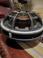
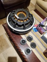
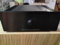
the focal crossblock is one of the few parts I kept from my few years in caraudio.
It's a wonderful piece that served me a lot in the car, but also helpful in home environment in the variable setup I tried.
It is built, I assume, for 4 ohms drivers so of course with 8 ohms everything shifts, but the wide range of adjustment still allowed a compromise.
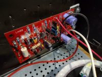
I used it few months ago between mids/highs on my OB setup, not optimal because with the drivers I finally chose it required heavy EQ, but ok just the time to find other amps/dsp.
I have now much better result active there too, plus gained time alignment.

I always wondered why there isn't anything like that for home, I mean with this flexibility and build quality, but maybe I’m just unaware of it.
DSPs are great and cheap now, but with 10 channels it doesn't hurt to simplify a bit, and I find it transparent sound wise.
I explored other active solutions like the k231 but they're a bit steep, and would require a bunch of spare cards for the same flexibility.
Anyway, I'm sure I will use it again one day, in the next version or next setup.
Or even right now I could use it to save two channels and maybe test new amps.

So the main question is: could I modify the crossblock itself, basically changing most components to better fit 8 ohms drivers?
I don't know much about crossovers, just how to use them but can't easily read/understand their schematics.
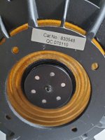
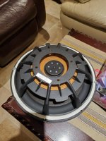
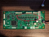
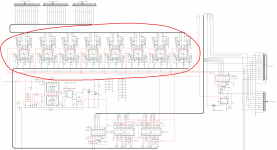
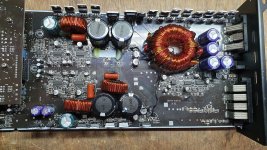
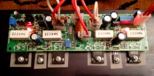
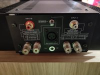
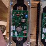
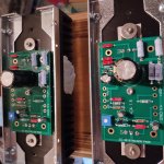
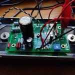
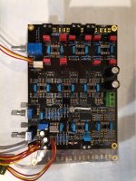
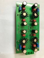
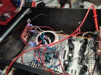
Once opened you can see how it's built (the 2 way version I have):

IMG_2168.JPG
IMG_2169.JPG


IMG_2170.JPG
IMG_2171.JPG


4 coils (big for woofers and small for tweeters?), few caps and a bunch of resistors, plus maybe few other things that I don't know (it appears two resistors have been replaced by the previous owner).
From left to right, 1st knob defines the low pass point, 2nd the Q factor, the 3rd defines the high pass point and the fourth acts as an L-pad.
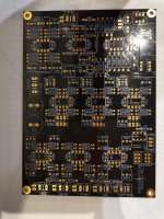
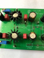
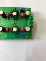
I suppose each knob controls a specific routing for a combination of coil/resistor to get to the desired slope.
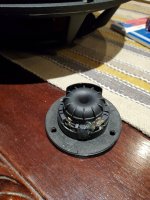
For the coil I'm not sure how it works, it looks like there's multiple soldered/entry points onto the pcb on their circumferences, is it possible that different pcb "tracks" arrive at different sections of the coil, for variable "rolled length"? If so it's not something I'm ready to change but I could still change the resistors.

The idea is to list all parts, find similar items but with half values for 8ohms (if I'm not wrong there), and solder them as replacement.
Do you think changing only the resistors would mess up everything? I assume the amount of combinations could still mitigate that.
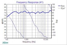
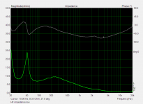
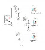
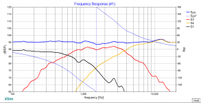
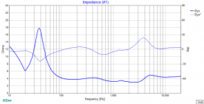
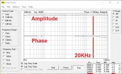
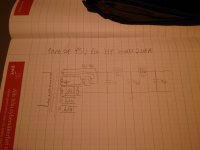
There's thousands of settings once combined, just to give you an idea for basic slopes:

crossblock t.jpg


What do you think? I’m nuts or it could eventually work? Thx!

Max power/excursion on SBAudience 18SW450 & rebalance system power

Hi all,

Now that I'm happy with my system even if still in progress (OB 4 way+2 sealed subs), I want to optimise the power needs and rebalance everything.
And maybe test different amps later, I'm planning on Neurochrome for different reasons (fun with first diy amp, and lower noise floor).

Current power (considering 1% thd for ease):
  • 60w on tweeter
  • 150w on high mid
  • 150w on low mid
  • 700w on midbass
  • 125w on sub (I sure need more power there and I'm waiting for a T.amp E800)
So I started with the voltage test from here https://www.diyaudio.com/community/...h-voltage-power-do-your-speakers-need.204857/
I did it at -30dbfs baseline for easy calculation, got of course very low voltages but it was not a surprise as I started with big amps for flexibility.

Then calculated the power needed for -0db:
  • 5w on tweeters
  • 5w on high mids
  • 60w on low mids
  • 360w on midbass
  • no test on sub, probably need 500w based on levels in minidsp

Considering that I can reduce headroom a bit since it's only few super loud parties a year, or when I'm gardening, I might be ok with 20-24db headroom, so all these numbers halved at least. I want more than 12db headroom to manage all kind of recordings, or bad tv stuff.
But these numbers already are low enough to find other kind of amps.

The pivot point seems to be the midbass, everything depends on them.
I can reduce drastically the power if I find the mechanical limit there.
To do that I need to get a ballpark idea of the max power to reach Xmax, or even Xmech that is a lot bigger on the SB.
They are crossed at 50hz but sometime I set them free.

I don't have winisd anymore, my parallel desktop is out and no pc around.
So I played a bit on loudspeakerdatabase with a faital hf510 that is very close to the sb18sw450.
After changing xmax to 11mm, in the biggest box available:
  • it crosses Xmax with 12 volts at around 20Hz
  • it crosses Xmech with 40v below 20hz
  • hard to simulate with crossover but once high passed it would probably not cross Xmax even with 40v, for 120+db per woofer.
I can't see myself needing more than that!
Here's where I'm a bit lost, the conversion to 4ohms once two woofers are wired in serie:
  • w/o crossover: 12v would give 18w per woofer at 8ohms, but 144w per side once wired in serie for 4ohms.
  • w/ crossover: 40v per woofer, that's 200w at 8ohms and 800w per side once wired in serie for 4ohms. I don't even know if the NC500 can deliver 80v.
If this is right, considering that all these numbers are rough estimate, I can barely reach their limits now with crossover, and I know I don't need more spl for sure.
And if so I can safely keep the current midbass amp, just being carefull when full range and play with much less power for the rest.


Do you see any mistake or miscalculation here?
Do you know a better way to find out about the midbass limits?

FS: ACA amp v 1.8 - 2 units

Built with premium components. Cosmetically so and so (see glue on bottom for instance) but perfect sonically. Sell 220eur each shipped to Europe. If both bought discount for sure. In case you want only the boards or stock Power supply make an offer for single parts

Attachments

  • IMG_20230109_182734.jpg
    IMG_20230109_182734.jpg
    458.8 KB · Views: 140
  • IMG20230109182522.jpg
    IMG20230109182522.jpg
    347.4 KB · Views: 145
  • IMG20230109182321.jpg
    IMG20230109182321.jpg
    305.2 KB · Views: 155
  • IMG20230109182515.jpg
    IMG20230109182515.jpg
    327.9 KB · Views: 159
  • IMG_20210730_120948.jpg
    IMG_20210730_120948.jpg
    429.8 KB · Views: 160
  • IMG_20210730_121013.jpg
    IMG_20210730_121013.jpg
    568.5 KB · Views: 162
  • IMG_20210801_174449.jpg
    IMG_20210801_174449.jpg
    462.3 KB · Views: 158
  • IMG_20210801_180823.jpg
    IMG_20210801_180823.jpg
    430.4 KB · Views: 148
  • Like
Reactions: Murdoc

Fisher 440-T MPX stereo low output Left channel

I have acquired a Fisher 440-T unit that had initially low output on almost everything. After replacing numerous 1uf coupling caps on the preamp and tone boards, I have adequate output except for low audio one just the left channel of FM. The selector switch makes no difference but the Mode switch will balance things out. My search online found a schematic for two versions of the unit, but unfortunately mine uses a different MPX decoder board than either schematics I've found. the serial number on mine is 64574D.
Any direction on where to look next is appreciated.

Tantalum capacitor in audio path

Hi

My general understanding was after reading tons of stuff that tantalum capacitors aren't the best for output caps in the path.
After doing some more research Im now more confused as I think my knowledge is rusty.
I have this DAP that uses 2x 100uf 6v caps (see photo).
I can see that there is space I could easily use. What path I should go if I'd like to do small upgrade?
1. Use nobium caps?
2. use electrolytic bipolar (won't fit larger than 22uf)?
3. use polarised electrolytic cap
4. add film/electrolytic/electrolytic bipolar cap as bypass?

Thanks,
doc

Attachments

  • 5a041f67a24d75944.jpg_e1080.jpg
    5a041f67a24d75944.jpg_e1080.jpg
    145.3 KB · Views: 287

Lindsey Hood 80W Amp for sale

I built this a couple of years after the original articles appeared in ETI in the early 80’s I was very pleased with it and would have said it was on par with the Musical Fidelity A1. But I digress. As you can see it suffered a mishap during some testing and the output devices on the LH channel were fried. Not long after I needed two matched stereo amps for active speaker so it never got repai. It’s in a 19” case and is effectively 2 mono blocks. The toroidal sae 300VA each. The anodised rear heat sink was custom made and only gets moderately warm with sensible use.

As I no longer have the rest of my gear it’s time it found a new home. I’d prefer a UK sale.

B83AD4E9-5D18-430A-8207-00380D176CAA.jpeg


Sensible offers please.

Tony
07D8F931-CA56-43B8-A19D-C10D4B565AFF.jpeg

FS. subwoofer filter+additional board

I have for sale an almost finished subwoofer filter+ additional board

Details can be found in this thread

35eur

https://www.diyaudio.com/forums/gro...e-sensing-eq-sections-12-24-db-lr-cutoff.html

Payment by paypall+ paypall fee+ shipping.

Attachments

  • IMG_20211114_172200.jpg
    IMG_20211114_172200.jpg
    552 KB · Views: 452
  • IMG_20211114_172221.jpg
    IMG_20211114_172221.jpg
    684.5 KB · Views: 453
  • IMG_20211114_172228.jpg
    IMG_20211114_172228.jpg
    691.6 KB · Views: 443

Scrap or use old tube PSU?

Just got the guts off a scrapped AF frequency generator made by HP, model 206A. It's way way gone but the tubes, sockets and PSU seem to be intact. I've been thinking of making my own tube PSU but now this one is just right here, was wondering if the PSU might be worth keeping as is for a DIY amp or if I should just grab the transformer, chokes and diode and making my own thing with it?

It has some 6L6 GB tubes(couldn't find any picture of the GB variant online so I've attached some 🙂 I think it's quite nice looking!) and a OD3 after the filter but I don't think I'd want to keep that part, seems like a waste of 6L6s to me. I'd rather use those for output tubes 🙂

Attached a sketch of the part of the PSU I'd be interested in keeping. I don't know what voltage the output would be though but if i finish salvaging/scrapping the rest I could potentially turn it on and find out. A bit worried about the caps, not sure if they are electrolytic or some other type. They are very large for being 4uF electrolytics even for 600V rated caps, but my references are more modern capacitors.

Attachments

  • 20230109_155846.JPG
    20230109_155846.JPG
    157.2 KB · Views: 107
  • 20230109_155912.JPG
    20230109_155912.JPG
    139 KB · Views: 93
  • 20230109_155908.JPG
    20230109_155908.JPG
    161.6 KB · Views: 90
  • 20230109_155901.JPG
    20230109_155901.JPG
    147.3 KB · Views: 92
  • 20230109_155851.JPG
    20230109_155851.JPG
    140.6 KB · Views: 123
  • 20230109_161057.JPG
    20230109_161057.JPG
    268.5 KB · Views: 106

Which full range?

A few years back I built a pair of Martello V0.10's for my wife using the FR88EX drivers. I just love the design & sound from these. Unfortunately the FR's are no longer available. The physical size of the cabinet of the martellos is just right for what I want to build. Is there currently another driver that would do justice to the same cabinet, or other driver out there with a similar size cabinet which will sound the equal or better? I have seen the FR88EX drivers sometimes on e-bay but the price is way over what I want to pay or I am wary of the seller or originating sales location.
Also is American Birch ply similar to Baltic birch?

Thanks.

For Sale Original PMI BUF03EJ fully populated PCB from Craigtone Audio

For sale is a fully populated PCB designed by Craig tone Audio USA which is having 4 pieces of Original PMI BUF03EJ installed.
This board can be used as Single ended or Balanced Buffer preamplifier.

light used and great sounding.
On board LDR volume option is not used.

I have assembly document from Craig tone Audio, which I will share with buyer through email.

Selling price: $120 including PayPal charges

Shipping to world will be under $20 through INDIA post Registered mail (trackable) which will take 2-4 weeks.

Thanks for looking.

Attachments

  • IMG_8218.JPG
    IMG_8218.JPG
    370.1 KB · Views: 228
  • IMG_8219.JPG
    IMG_8219.JPG
    385.7 KB · Views: 244
  • IMG_8220.JPG
    IMG_8220.JPG
    313.1 KB · Views: 218
  • IMG_8221.JPG
    IMG_8221.JPG
    292.4 KB · Views: 225

Linn LK100

An Old Chestnut,

I have an old Linn LK 100 that is cutting out minutes after switch on. I have seen posts on this before and have followed some of the advice in faulting the board but everything I have changed makes little or no difference. Basically I need some further help to cure this issue

I am working from the cct diagram previouly posted, but I don't have a diagram for the power supply or a complete schematic.

I have the +/- 40 volt rails.

The = +30v rail is reading +32.6 volts approx and the - 30v rail -29.5 volts.

The DIS point is + 42 volts when amp is working and swings to - 28 volts after cutting out.

I have changed most of the capacitors, diodes, transistors up to Q207,Q209, Q307,Q309 respectively and I am unable to find as yet a faulty component and the same fault remains.

Any help or advice would be welcome.

New motor for Oracle Delphi MK II ?

Hi,
I bought one old Oracle Delphi MKII with broken Papst Motor. I am looking for a new motor for Delphi.

There is one Origin Live kit for Oracle and others turntables.

Turntable Motor and Power Supply Replacement - Money Back Guarantee

Oracle Delphi Motor Supply Kit Fitting Instructions | Origin Live

I am thinking about buying it, but it is not so cheap. Does anybody know which exactly DC motor type is it ?

Or maybe somebody can advice me, which motor should i take ?
Premotec (like in LP12 and many oters) could be interesting.

I have Heed Orbit 2, so i could use it with it, i just need a right pulley.

I will be thankfull for any suggestions.

Ampslab Lm60Mk2

I mentioned in another thread about this as a side not but figured I'd post an actual thread in solid state.
I recently completed a lm60 build. I've cleaned up the wiring some from the one picture. Ive been running it for over a week and am quite happy with the sound. It replaced a SE tube amp using 6L6GC tubes. It has a nice full sound with warmth but still plenty of detail. The transistors don't even get warm on those heatsinks.

Attachments

  • IMG_20220402_200814044_HDR.jpg
    IMG_20220402_200814044_HDR.jpg
    386.1 KB · Views: 208
  • IMG_20220402_195046_01.jpg
    IMG_20220402_195046_01.jpg
    451.5 KB · Views: 201
  • Like
Reactions: DCE1198

BSS Soundweb 9088iis network hardware issue

Hello to everyone and happy new year.
I have in my stack 1x sw9088iis dsp, 1x sw9088ii dsp and 1x sw9000ii hub all linked together.
this year we have some problems like slow turn on, pop outs etc.
I buy nippon caps rated at 105 celcius for PSU for all soundwebs (and new fans also) and after installed (and proper service / maintenance
) problems are gone away.
To the point, because the club have many zones i buy a used sw9088iis to put in my stack too. soundweb have same problems as mine but network isnt working. Leds inside for network and arround DSPs wont illuminate. After servicing like recap, bad solder points at psu, sw turns on but at the same condition. i've tested inputs / outputs, its working like a charm.
psu give +/-16vDC, +5DC, 60vDC (phantom)
Other regulators at network like 2.5vDC, 3.4vDC are working.
Voltage tests points like +15, -15vDC etc measure the reported voltage.
I'm professional electronics engineer specializing in sound systems but i dont have schematics to do proper searching.
i've tested with debug pins, front serial at 38400 baud rate, auxliary serial at back at 115000 baud rate. network in/out without solution.
My other soundwebs are communicate with my usb/serial dongle

SMPS in F5 class A amp failure

Hi! I tried to feed Pass F5 with idle at 2 A with two Meanwell LRS-150-24 (23-27 V, 5 A) pch with the original 2 x 47,000 uF capacitor bank left. It worked well with no load, just the capacitors,. The voltage was stable at 26 V and i tried plenty of starts without any problems. But with the amplifier the SMPS constantly starts and stops (excuse the pun...) as if it was overloaded. I will put out the capacitors as a next try (but I really want it there, for the current capability), but does anyone know what's going on or what to do?

Older Fostex FF165K creased dust cap help and fix please?

Good Afternoon Everyone. So I bought a pair of FH3 from a fellow diyer with Planet 10’s Enabled treatment done to the drivers. I unfortunately bumped the dust cap by accident 😢. I was able to get all the damage removed but, the crease underneath the middle of the dust cap and a oval shaped discolored spot above the crease. So how to fix it suggestions?

1. Cut the dust caps off and replace them with new ones (Not treated)?

2. Cut the old dust caps off and put a wooden phase plug in place instead of the dust cap? I might be using a tweeter and just let the driver naturally roll of and cut the tweeter in at 2,700 khz?

3. See if I can send them into fostex to get fixed by them senc. that have all the glue and parts on hand? Could take months Madisound has already e mailed me back about this? Or I could see if they would send me a replacement dust caps?

Please tell me what you think? Here are a few pictures of the damage.🤦🏼

Attachments

  • 6593CB1A-1A2B-4D26-8980-91C9FD02C665.jpeg
    6593CB1A-1A2B-4D26-8980-91C9FD02C665.jpeg
    378.3 KB · Views: 115
  • F9F32870-79CA-4004-9258-29C82B381BD4.jpeg
    F9F32870-79CA-4004-9258-29C82B381BD4.jpeg
    258.4 KB · Views: 112

Amplifier overheating

About a year ago I built a pair of loudspeakers based on a Visaton kit - "La Belle". These speakers have a low sensitivity of 81db and are rated 200WRMS, nominally 4Ohm. I didn't use the pre-assembled crossover and instead built my own, using "better quality" parts with the same ratings as in the Visaton crossover.

My power amplifier is a Perrreaux PMF2150B Mosfet amp which has been extensively upgraded, including the 2 big caps which are now 4 smaller ones that double the storage capacity. The amp was tested at 406WRMS @ 8Ohms single channel driven after the upgrade. The pre-upgrade rating at 4Ohms was 400WRMS both channels driven, with enormous headroom. It is claimed to be able to drive difficult loads. SO, I think the amp should be more than capable of driving the speakers to a decent listening level - theoretically about 100db at my listening position at rated power.
Anyway, recently I played an LP pretty loud. According to the dB meter app on my smartphone, average 85db with 95db peaks. That's as loud as I want to go. I just happened to notice that the front panel of the amp seemed very hot after playing the whole LP, so I measured the heat sinks with an IR thermometer, and they were pushing 60C, which is dangerously hot.

I swapped out the Perreaux for an old pair of mono amps and a different pre-amp. These amps got hot too, but they are rated at less than half the power of the Perreaux, and have less than half the heatsink area, so perhaps not a huge surprise. Both power amps are within a degree or so of each other so it doesn't seem like 1 speaker is to blame.

So, that's the background. I hope it's not too long winded and I haven't lost everyone!

I guess my question is what might make the amp overheat so much?

The sound meter app could be understating the SPL, but even so I should be well within the capability of the Perreaux, if not necessarily the Linx monos. The Perreaux should be able to blow up the speakers before the speakers melt down the amp.

I might have wired the crossover wrong, but wouldn't that be audible? To my ears the speakers sound good, and I haven't noticed a change in the sound recently, except maybe that I have had to wind up the volume more recently, but I might be wrong about that.

All of the individual speaker drivers (2 woofers, a mid and a tweeter) seem to be behaving. At the sort of volume I had them playing at, the woofers were moving a lot - not sure how close to their excursion limit, but a lot. The bass is rock solid and no frequency particularly stands out.

I am going to book the amp in to have it checked over, but I have no idea how I would check the speakers. They weigh 40Kg each so pretty hard to move if I wanted someone with more knowledge to do it. If it's my crossovers then it's both, and if it's something like a solder joint, then wouldn't it show up in the sound?

I have tested both speakers individually with a white noise test tone and according to my spectrum analyser app the response is almost dead flat from 50Hz to 15kHz, when it ticks up about 8 dB to 20-ish. In fact, and I find this surprising, it's almost identical to Visaton's published frequency response graph except for that last bit. The published response dips about 3dB at 12kHz, then rises 5db to about 18kHz. I'm under no illusions about the accuracy of my phone's mic, and in any case, there is nothing particularly strange about graphs with real music as opposed to white noise.

So, i hope someone has some insights that they wouldn't mind sharing with me. Maybe this is normal?
Screenshot_20230109-161123_Advanced Spectrum Analyzer PRO.jpg

Pronounced highs and lack of bass on 1500 hours+ old Aleph J

Hello forum,

it´s great to have a platform like you, that makes it possible to get into audio segments never been thinking of.

On my audio road, I`ve built an Aleph J some times ago, driven by a Salas UFSP and a Transcendent Sound phonostage.

Unfortunately my hifi rig began to lack of bass and pornounced highs in the last days, without chaning anything. At first I tried another phono cart, then switched between the two ponostages an nothing really changend.

So my suspicion is, that something went wrong with the main amplifier. Been using it excessivly in the last hot summer and noticed that the electrolytics got really hot.

What do you think? Can this be the reason for the sound probs (drying out)? All parts look normal. Bias is checked and ok. No audible humm.

Many thanks and best
Rents

SB Acoustics vs Seas, small active sealed 2 way

I have been thinking to build a v. small(~8ltr) active 2 way sealed standmount(with possible stereo subwoofers crossed ~150Hz). Crossover will be done using Minidsp Flex 8.
On tweeter, I am thinking between Satori TW29TXN or TW29BN - is Beryllium version worth the added cost?
On Woofer, my choice would be either SB17NBAC(cheap but gets good reviews) or Seas W18NX001(mid budget) or Seas W18NX003(with this one I would prefer cheaper tweeter, maybe TW29RN).
Are Seas drivers worth the added cost? W18NX003 would probably get away without subwoofer if I EQ it - my amp is Hypex nc252mp for bass.

Ancient Linn LP12 power

Hi! First post here, I’ve read about the forums but haven’t seen anything on this so thought I’d ask people who may know…

I have an old Linn LP12 (fairly sure it’s a 1973) with the old pre-basik choc-block power arrangement consisting of simply 2 capacitors.
B7AD34EC-37E0-4503-A90A-8956FFC369DC.jpeg

Recently the motor lost power (ran at half speed and even jumped into reverse a couple of times) so I replaced it to a slightly newer one, but still have problems.

I’m now thinking I’ll replace the 2 capacitors as it may be they’ve just had enough after 50 years of service. From what I can determine, one is a large grey Plessey 0.22uF 300VAC/600VDC, and the other is a mustard 0.22uF 400VDC.

I know enough electronics to swap things about and not kill myself in the process, but not enough to know if there’s a reason I can’t just replace these with 2 identical polypropylene metal film caps (0.22uF, 630v seem easily available).

I can’t manage to source a 400v 0.22uF mustard anywhere in the UK yet. I can see 160v but that’s the best I’ve found.

Any advice would be appreciated. I have thought of a Hercules upgrade but funds aren’t there at the moment and I don’t really want to buy a Valhalla knowing it’s only a stop-gap.

DCG3 by myleftear: Mishaps, questions, construction and other otherwise offtopic stuff

As my quest to a Salas DCG3 nears its end and most of my preamp already functional, it is time to go ahead with my off-topic side-notes (those that otherwise would clutter Salas original thread).
So I will post my mechanical etc. weird ideas right here, brag about going where so many others already have been, etc.
Comments, questions, tips, scoldings, all welcome!

Need help with what tube is missing from an unknown 6V6 push pull stereo amplifier

I recently purchased a 1957 Berlant reel to reel drive unit with 2 mono TWA-1 recording amplifiers all built into red Berlant carrying cases and a unknown built 6v6 push pull stereo amplifier that is built into a very well-done reproduction of the Berlant cases, these itemns are in superb physical condition but am having a problem with the custom amplifier, it uses all Stancor transformers and vis a 2 channel 6v6 push pull that has 2 x 6v6 1 x 6J5 & 1 X 6SJ7 for each channel but in-between the in an empty socket for a rectifier ? im guess but wondering what would be the correct or at least safest to put in there once im ready to put it on a variac and see what happens. First two photos are the recording system third photo is the home brew amplifier designed into a look alike case, next is to show what tubes are where and what is missing then the inside of the chassis then the bac of the amp with connections. I not very knowledgeable about this part of enjoying audio, just enough to get myself into these situations and any help or ideas on what tube is missing it would be greatly appreciated, Thank you.
20230103_125358.jpg
20230103_130605 (2).jpg
20230106_222352 (2).jpg
20230106_224958 (2).jpg
20230106_223859 (2).jpg
20230106_223921 (2).jpg

Hifisonix Ovation SX class A dual mono power amplifier

For sale is a Hifisonix Ovation SX power amplifier. 2x15W Class A. More details here: https://hifisonix.com/projects/sx-amplifier-audio-power-amplifier/

This is a dual mono version with Toroidy supreme 250VA power transformers (2pcs), KEMET 56.000uF (4pcs) filter capacitors, soft start and speaker protection, power on delay, vandal resistant power switch, MCU controls the operation, etc. PTFE / silver and Kapton / silver wirig (except power supply). Only premium parts used (e.g. Nichicon and Kemet capacitors). Soft start unit is Chinese el cheapo

Enclosure is hand built from scrap aluminum and it is heavy. Dimensions 480mm x 160mm x 370mm, weighs a lot.

Here is the thing - It was in everyday use for a year or so, then suddenly one channel dropped off generating only some noise in that channel. I don't have time to debug it further.

Price: firm 250€. Can be shipped or picked up. This is located in Finland, Europe.

Here are some photos:
PXL_20230108_101937908.jpg

PXL_20230108_101951471.jpg

PXL_20230108_102001681.jpg

PXL_20230108_102125398.jpg

PXL_20230108_102148483.jpg

PXL_20230108_102157459.jpg

PXL_20230108_102157459.jpg

PXL_20230108_102204897.jpg

PXL_20230108_102223155.jpg
  • Like
Reactions: manniraj and Jcris

I need a Buffer with gain?

I purchased a low output (1.0 mv) moving iron cartridge to transcribe my rarer vinyl to digital. I plan on using the single ended tape output of my preamp to a studio type adc/dac (RME). The RME analog input is either +4dBu, +13dBu,+19dBu or +24dBu. The output from my preamp is 100.0 mv for 1 mv in. I need a "line level" amp to make up the difference. I'm thinking +13dBu is the target. My first thought is to build a ACP+ preamp/headphone amp. Is there a better Pass design for this need. Output impedance from the preamp should be about 330 ohms, the input to the RME should be about 9k unbalanced. I wouldn't think impedance in or out would be much of a problem. Temporarily I have proven my concept using a dual channel HP instrumentation amplifier in single ended mode in and out. I need a gain of 10x +/- a skosh. My skills use to be high, so even at my age I think I'm up to it. For reference, in 1977, I built a couple of A20s an so on. What are your thoughts?

Thanks in advance to all.
Bill Taylor

Question comparison F6/M2x, Bias setting on M2x? (noob question probably)

Hi

I am studying both F6 and M2x, willing to build one of them.
For the F6, i understood from the manual/diy build thread/Youtube video that you have to adjust some pot to adjust bias. 2pots to adjust, documented.
For the M2x, i didn't find much information if there is a bias to set or not and would like to check with you.
*On the schematic, the pot RV1 is mentionned as not mandatory / used for a bit of tuning only. [6L6 answered below= was wrong, RV1 is mandatory]
*Don't remember where but there was a mention of the bias adjusting itself automatically just by design.
*Googling "F6 bias" will return results. Same with M2x doesn't return much / nothing (same on those foru

I am quite new to this, having just recently repaired a tube amp (recaps, changing ageing resistors and others misc), assembled a Noir amp.
I might not have understood the schematic and not search enough, but i would like to understand if i missed anything (and where that would be !)

Regards

"SilentSwitcher" with USB PD

Here is a "SilentSwitcher" with USB PD support. The board has a STUSB4500Q USB PD controller that can work as stand-alone USB PD sink. Otherwise the board is similar to Jan's original SilentSwitcher. High voltage output has slightly higher current capability (+/-15V@250mA) and LDOs are LT3045/LT3094. Max input voltage of the board is 16V.

Many modern power banks now offer higher voltage output through USB PD (e.g. 5V@3A, 9V@2A, 12V@1.5A). This is very useful for these switcher boards as full output (+/-15V@250mA, 5V5@800mA) at 5V input leads to very high startup currents (>2A). Many mobile power banks are not up to such high currents. With higher input voltage the startup currents are much smaller so full output is possible even from smaller power banks.

STUSB4500Q can be configured via I2C. I've set the USB PD PDOs (Power Data Objects) at 5V@2.5A, 12V@1.5A, 15V@1A. These should work with most mobile power banks. The board can of course be used without USB PD.

sslpd1.jpg
  • Like
Reactions: StevenCrook

MTX 81000d (old design)

Good evening, I have an older mtx 81000d that came in with pretty severe input RCA jack damage. Also inspected all output and power supply mosfets, nothing blown. Powered the amp up, power supply powers up without issue, builds rails voltagr but zero output.

I checked for output switching and there is none. So I disabled the output stage by jumping the capacitor pictured and began to trace the input signal. It looks like the audio input enters into pin 3 of the NE5532. Upon powering the amp up, the audio signal vanishes on pin 3 and is replaced with 2.39v DC which appears to being fed into the TL072 next door.

Is this normal or is the NE5532 damaged? Pin 8 on both the NE5532 and TL072 show 15v.

Thank you in advance

Attachments

  • 20230106_193641.jpg
    20230106_193641.jpg
    625.1 KB · Views: 154
  • 20230106_193654.jpg
    20230106_193654.jpg
    658.4 KB · Views: 175

Can anyone identify this mystery chip?

I have about 150 of these 8 pin DIP chips still in their original Texas Instruments tubes. I probably got them in one of many surplus lots of parts I got at least 20 years ago. The parts are marked Ti 4130A2T and 321581. There is a circle on the back with TAIWAN across the middle, 16 above the TAIWAN and J3 below it.

Attachments

  • 4130A2Tchip.gif
    4130A2Tchip.gif
    1.1 MB · Views: 200

JST, Molex KK, .250 FastOn connectors and crimp tools

Hi

I'm relatively new to building and assembling electronics and found myself having to learn about various connector types and reading up on crimping vs. soldering. I stumbled upon what I think is a good website explaining the various connectors, an explanation of various crimp tools and what a good crimp vs. a bad crimp looks like and why the OEM tools are so expensive. Ultimately I couldn't justify splashing out on the OEM tools, but still managed some decent crimps with the more affordable tools.

Matt's Tech Pages

I ended up purchasing the IWISS SN-58B for .250 FastOns and the IWISS SN-2549 for the JST / Molex. I'm pretty happy with the results and glad I didn't resort to using needle nose pliers or soldering. Now off to find a good wire stripper.

PSUD2 for Mac released

I've been asked for this for years, eventually went out and bought a MacBook Pro so I can do some "Mac" stuff 🙂

PSUD2 Mac version build 73 can be downloaded from the following link http://www.duncanamps.com/psud2/psud2_build73.dmg

When you download it will refuse to play ball and say "“psud2_build73.app” cannot be opened because the developer cannot be verified."

Use the two finger light tap to get the context menu up and select Open. The app will try to install the example files and rectifiers into your home folder, it will ask permission to do this.

The app can be moved somewhere else, like your applications folder and this will get round the messages every time you try and use it.

If there's sufficient interest, I'll invest in an Apple Developer account to get a cleaner install.

Please keep the thread to the Mac version only as I'd like some feedback on it. There's another thread on the go for the Windows version, thanks.

Regards,
Duncan
  • Like
Reactions: trobbins

did anyone here keep my sketch for the 1955 Karlson K8? (mine is gone)

here's the cabinet in question, This was from a kit and with a single 10 degree forwards cant vent board. I'd like to have this plan for the "heritage" part of an upcoming Karlson compendium thread.

I do have a sketch of one K8 from Scott Nixon but that one doesn't match my cabinet so perhaps was a knockoff (? - the late Wayne Green said there were a number of "factories" producing Karlson cabinets in their heyday)

Karlson 8 cabinet from ~1955 with Tangband 1772 - YouTube

Denon PMA-980R opamp upgrade!

Hello guys, i have an old Denon PMA-980R amplifier who needs some re-caps and i have decided to make un upgrade to opamps. I'm not an engineer, i have looked into service manual and i not understand too good if IC701 has a voltage +/-16.5v or just +16.5v.
For +/-16.5v, i was searching opamps with +/-18v and in this days is verry hard too find what you want! Amplifier has 4 opamps and i'm thinking to put Ad8599/ad8066, opa1612 (but i can't find it) lt1469/lt1358 or dual lt1028/ada4627!
I need some help for choosing the right opamp voltage!
Thank you!

Attachments

Split Supply to Single Supply for Class A SE -simple amp-

Hello Everybody,
So I require some help to solve a quite straightforward task, that is modifying a class A SE amplifier so it will use a single power supply instead of a split one.
The amp to be modded is
1673194719016.png

available from: https://sound-au.com/project10.htm

The idea is to change the +/- 20V to a single +40v, of course adding an output cap...
I have not been able to succeed in such a task.
Your help is welcome 🙂
Please do not make suggestions for :
-keep using it with a dual supply
-change this or that to make it a boring amp (most often called "blameless")

I also attach the LTspice file as I believe it will be useful 🙂

This was a personal exercise that I was not able to do on my own, thanks for your help!
cheers from Switzerland

Attachments

The components I purchased from suppliers have different markings following the positioning holes. Does anyone know the reason? STM32F103RCT6

I purchased two batches of components from the same supplier, with different positioning holes on them, and the markings seem to be different. Have you ever encountered this situation? Has anyone purchased components from this smt factory? https://www.onepcba.com/STM32F103RCT6TR

1.png
2.png

Lateral Mosfet Bias Issue

I have purchased B&K 200.2 that has one channel with ~30Vdc on the output. After removing the channel, checking all the resistors and diodes (and fuses), the Lateral Mosfets measured off in diode and resistance compared to the other channel. I removed all 5 and tested out of circuit and 4 Lateral Mosfets and their drain resistors were bad. I replaced all 5 Lateral Mosfets with what I'm 90% confident are originals I bought from a reliable source 4-5 years ago and have used in 2 other amp builds.

That said - here's the bias issue... possibly, because it doesn't match the other channel. The replacement K1058s are only getting to 6-8mV of bias, when the J162s are getting to the specified 22-25mV. All 5 J162s are within +/-2mV and all the k1058s are within +/-2mV, just low by 15mV compared to the J162s.

I have gone so far as replacing the 5 J162s with the corresponding replacement Mosfets (all K1058s and J162s have all been replaced from same source) assuming there was a mis-match with the 20+ year old J162s. Exact same Bias after replacement.
I have since pulled all TO-92s and TO-5 drivers and measured out of circuit and replaced the J162 (Q13) driver that was low on Hfe and now both drivers match Hfe (~70). Again no change to the bias and amplifier channel performs exactly the same.

I can adjust bias, it plays music, doesn't overheat - but my OCD can't get around that there is something I'm missing, because the other channel is +/-5mV across all 10 outputs (22-27mV)

Am I going crazy, does this difference really matter or possibly a simple explanation and I can fix the problem? Can't get specific schematic to extract, so I'm including the entire Service Manual for 200.5-200.7, amplifier board schematic matches my amp boards 99% (only difference is there is 3k gate resistors on K1058s, not the 1.5k on the schematic).

Thanks for reading the long post and looking forward to gleaning some of this group's vast knowledge to figure this out (or confirm it doesn't really matter).

Attachments

For Sale Mcintosh MA252

Item: Mcintosh MA252
Location: Georgia, United States
Item Condition: excllent
Reason for selling: Not used after upgrade to MA 352
Price: US$2200+ postage.
Payment Method: PAYPAL BUYER PORTECTION
Extra Info:

Excellent condition MCINTOSH MA252 integrated amp for sale.
Incudes original boxes, remote and manual.
It was purchased demo from authorized dealer in Las Vegas in December 2020. Can provide invoice for proof.
But due to covid less then 50 hours in use before I purchased.
Upgrading to MA 352.
I accepte offere

Attachments

  • 3940405-539440f3-mcintosh-ma252 (2).jpg
    3940405-539440f3-mcintosh-ma252 (2).jpg
    83.2 KB · Views: 252
  • 3940404-99f7e7b6-mcintosh-ma252 (2).jpg
    3940404-99f7e7b6-mcintosh-ma252 (2).jpg
    102.4 KB · Views: 242
  • 3940403-7099d761-mcintosh-ma252 (2).jpg
    3940403-7099d761-mcintosh-ma252 (2).jpg
    111.7 KB · Views: 240
  • 3940402-e944956b-mcintosh-ma252 (2).jpg
    3940402-e944956b-mcintosh-ma252 (2).jpg
    87.8 KB · Views: 235
  • 3940406-ce721c86-mcintosh-ma252 (2).jpg
    3940406-ce721c86-mcintosh-ma252 (2).jpg
    118.5 KB · Views: 235

Closed box with Eton 8-412-C8/32 Hex 2 or 3 way

Hi

I would like (for the first time) to build a closed box, volume around 65 liters.

As woofer I have an Eton 8-412/C8/32 HEX
As tweeter I have a Visaton KE25SC (which I like a lot)

I also have a pair of Eton 4-212/C8/25 Hex cone midranges

The question is: 2 ways or 3 ways.
When looking at the frequency responses the woofer is usable until 2000Hz, and the tweeter is usable from around 1200Hz. My guess is that a 2 way would easily be possible using higher order filters, but I am not sure...

Any opinions would be highly appreciated.

Thank you and best regards

Christoph

Attachments

Help with the Zen Mod oscillation detector

In post
https://www.diyaudio.com/community/threads/signs-your-firstwatt-diy-is-unstable.186833/post-2536178
there is mention of an oscillation detector.

Again, in another thread it is further discussed
https://www.diyaudio.com/community/threads/the-little-oscillation-detector.215848/

The led's I chose have a forward voltage of 2v, but actually start glowing at 1.8-1.9 volts..
Today I hobbled it together as a proof of concept and wired directly to my signal gen.
I tried sine wave at 20k, 25k and 30k. Tried at all frequency's at 2, 2.5 and 3V
Swapped out a the 4n7 ceramic cap for a 4n7 mylar cap
Nothing I tried can get those buggers to light up...
Checked with the scope, and sure enough, the signal generator is chooching, but no joy...

Any ideas on what I could be missing ??

Attachments

  • oscillation detector.GIF
    oscillation detector.GIF
    2.5 KB · Views: 109

DIY speakers for HQ low volume listening

Hi,
please advise how to deal with the following requirements.

I prefer to listen acoustic music, from classical music, early baroque music and opera to jazz to ethnic music, the human voice, acoustic instruments. But sometimes a bit of some electric music - jazz, blues, rock (no metal or so, but classic rock like Santana, Yes, N.Young, some indie rock - Zalmani etc).

I prefer listen at low volumes - to preserve hearing from demage and to relax without getting tired of too much noise. My dedicates hifi room is small (3.6x4.8m) so optimal distance of speakers is about 1.8m.

I assume the use of an amplifier Marantz PM7000N (reviews are good and I like that it's all in one solution for playing FLACs from USB disc and for internet radio).

I have looked for some loudspeakers, but commercial types that are on offer in our country meet what I need. I find that they are tuned for higher volumes, they do not play well at low volumes. Also, none of the ones I tried convinced me by their performance of acoustic instruments and voices (tember, color, ambient sounds).

I'm thinking about building my own speakers. Can you advise me which concept to choose, some projects that would meet my ideas?

At present, I already have a very old set of Dynaudio Audience 10 bookshelf speakers and Marantz PM44se amplifier. Of course, I would like to achieve a significant improvement in sound.

Thanks in advance

USB scope and spectrum analyser 18 mega samples 1MHz bandwidth

18 mega samples/second dual channel USB scope.
Analogue display and spectrum analyser display.
No trigger, positive and negative triggers.
Good up to about 1MHz so good for audio work.
Data logger for saving a stream of screens and replaying them.
2 volts per division but can do up to 200V/division with x100 scope probe.
£35 including p+p to UK only.
scope2.png

scope1.png


100_0537.JPG
Projects by fanatics, for fanatics
Get answers and advice for everyone wanting to learn the art of audio.
Join the Community
507,551
Members
7,876,518
Messages

Filter

Forum Statistics

Threads
405,702
Messages
7,876,518
Members
507,551
Latest member
mbwiest