Interest in a Soekris DAM1021 motherboard

Hello all,

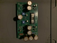
A friend and myself want to build the rev.7 of the soekris dam1021, but there is not much option to get proper control for it, with screen and remote. So we are in discussion to build a board that include everything we need.
Thanks to Dimdim there is arduino code for a small oled panel that offer volume / source / filter controls. There was a GB here for this board, but it's long gone and Dimdim do not answer my solicitation.
Before continue i want to be clear that the goal of this topic is to judge interest on this, to see if a GB is possible and how many people are interested. My friend is a professionals electronics that is doing this on his free time, and he doesn't have much of it. So there is no warranty.

What we want to do :
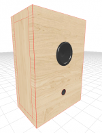
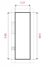
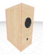
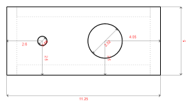
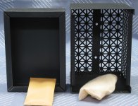
  • We target a small size case, i want Takachi uc20-5-14DD
  • Arduino Nano with Oled Screen, isolated
  • External PSU block / wall mount (meanwell)
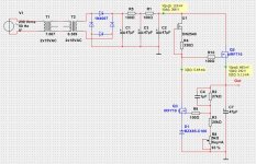
  • Ldovr external Low noise reg, lt3045/3097 in +-9v for the DAC, and probably another one in 5v for the usb board.
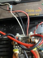
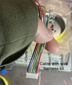
  • JLsounds usb board connector plus SPDIF/Toslink. We hesitate between JLsounds pinout and Amanero pinout, because JLsounds has his board with Amanero compatible size and pinout.
  • I want space on the PCB to use the universal buffer by neurochrome. Plus a jumper if you don't want to use it and use the integrated opa1678 buffer instead.
  • An On/off switch control by the arduino.
  • I don't know if we'll keep it fully balanced or keep using a single ended rca connectors. Space is limited, so please tell me.
  • There is a discussion to integrate a usb to rs232 adapter, for easy firmware / filter upload.

Of course every suggestion is welcome.

Regards

Any experience with Sony speakers?

I have a pair of old Sony Speakers on my desktop. I've tried other speakers but unfortunately I like the sound of these. Because I live in an apartment the speakers are dually tasked to work as satellites but still sound decent at night without the sub. My one criticism is they can sound boxy when pushed.
It could be down to my inexperience or maybe its just stupidity but if the manual shows they can be disassembled - it should be possible, right?
I've tried gently prizing everywhere but I'm afraid I'm going to break them.

Any tips?

ss-fse9.JPG

Transformer output not matching

I have spent months trying to get my chip amp to sound better.
Been doing a lot of reading. When I cam across this sentence.
Measure weather the positive and negative output voltages are symetrical.
They should be within 0.6 V of each other. This test is done under zero load.
So I tested all the transformers I have. Some EI some toro all have more than 0.6v variation on the output.
Maybe they just make shitty transformers in my country.
Another friend told me it does not matter what the difference is. It just means that one side will clip sooner than the other when pushed to the limits.
Other than trying to import a transformer how do I fix this. Do I need to worry about it ?.
I have tested direct output from the transformer and also after the voltage is passed thru the PSU board.
This pertains to my tda7294 and lm3886 builds.

How flames behave in space.

I found this gem flying in the ham radio packet network published by EI2GBY. I paste it here as is. I ignore copyright(s) and the like.

Great balls of fire: How flames behave in space.

Researchers are keeping a close eye on these spherical flames. Their findings could help both astronauts and the earthbound.
By Marisa Sloan | Published: Friday, January 20, 2023

Given that it's one of humanity's oldest tools, you might assume we know all there is to know about fire. And sure, we know a lot: As hot air near the base of a flame rises, gravity pulls in colder, denser air to replace it. It's this cycling of air that provides fresh oxygen and gives flames their characteristic teardrop shapes.

But in a microgravity environment, like the one astronauts experience while in orbit, all bets are off. Here, hot air still expands outward - but it doesn't move upward, because there is no "upward." Instead, fires in space are fed only by the random oxygen molecules that stumble into them by chance.

It's a process called molecular diffusion, and it produces spherical flames that are different from their Earthly counterparts in more ways than one. Not only do they burn much slower and for longer periods of time, but they also survive on less oxygen and clock in at less than 900 degrees Fahrenheit - a fraction of the heat given off by most terrestrial flames.

And yet, there's still much scientists don't understand about how fire operates in microgravity. Are certain materials more flammable than others? What's the best way to extinguish a rogue flame?

These questions are critical for the safety of astronauts already living and working in the International Space Station (ISS), and will only become more important as humans prepare for longer space voyages. Luckily, NASA scientists are on the case.
Fire aboard

To be clear, the threat is not merely a hypothetical one. In 1997, for example, a fire ignited aboard the Russian space station Mir; it originated in an oxygen generator, filling the station's modules with toxic smoke and cutting off access to an escape vehicle during the several minutes it lived.


One of the reasons fire is so dangerous in space is its lack of predictability. Unlike on the ground, where gravity forces flames upward, flames in a microgravity environment can spread in any direction at all. The same goes for smoke, making the placement of smoke detectors in a space station (typically on the ceiling in most buildings) much more difficult.

Though the Mir crew quickly doused the errant flame with a fire extinguisher, preventing its growth, extinguishers that use gases to snuff a flame are less effective in space than on Earth. For one, the apparatus can literally fan the flames of a fire by directing air - and therefore, oxygen - toward it.


In the end, the flame extinguished itself only when the oxygen generator had emptied. Over the next several hours, the station's life support systems cleared Mir's atmosphere of all smoke, and the crew escaped the incident without significant damage to either themselves or the station's structure.

Playing with fire

OK, so we've established that sealing up these gaps in our knowledge about fire's behavior is clearly important. Now, how exactly do scientists do that?

Well, in 2008 NASA created their Combustion Integrated Rack (CIR) and sent it to the ISS. Used to safely fiddle with controlled combustions in microgravity, its hardware includes a 26-gallon combustion chamber and five different cameras that have been put to good use in thousands of tests over the past 15 years.

Many of those tests were part of the Flame Extinguishment Experiment, or FLEX, which began about a year later. As the name suggests, these revolved around putting out fires in space and ultimately improving fire suppression systems on future spacecraft. With the help of CIR, researchers aboard the ISS would ignite tiny droplets of either heptane or methanol fuel and record the results.

Daniel Dietrich, a scientist at NASA's Glenn Research Center, told the administration that "one of the biggest discoveries, not only in the microgravity program, but in probably the past 20 [to] 30 years of combustion research has been during the FLEX experiments on the space station."

The discovery in question? After certain liquid fuels are extinguished in space, they spontaneously reignite. In these cases, the subsequent flame - called a "cool flame" - burns at lower temperatures and is invisible to the naked eye.

Scientists aren't sure exactly why this happens, but from a practical point of view, we could use such low temperature combustions hypothetically to produce fewer air pollutants in diesel engines back on Earth. We're far from that reality, though research conducted in June 2021 took another great leap when it repeated the phenomenon using gaseous fuels, rather than liquid ones.
Bringing the flames home

Arguably the best part of studying flames in space, however, is that the lack of gravity just . makes things simpler, in a lot of ways. Whereas the candle on your coffee table may flicker, for example, as a result of buoyancy-driven instability, this isn't the case in microgravity.

Another series of NASA studies, the Advanced Combustion via Microgravity Experiments (ACME), took advantage of this to really dig into what makes a good flame - one that is efficient but doesn't give off a ton of pollutants like soot. Beginning in 2017, ACME scrutinized more than 1,500 flames in the CIR, over the course of more than four years.


The next step in NASA's research is SoFIE, or Solid Fuel Ignition and Extinction. This set of experiments, launched to the ISS in February of 2022 and expected to continue until 2025, will help the administration choose the best fire-retardant materials and designs for "spacesuits, cabins and habitats."

A whole host of materials is in line to be tested, including plexiglass and cotton-based fabrics. Afterward, SoFIE's results will even be applied to mathematical models that forecast how those same materials might burn in conditions outside of microgravity - including on the Moon, Mars, or elsewhere in our solar system.

But we aren't stopping there: The results could be felt all the way back on Earth, if they potentially revamp fire-safe materials for our homes, offices and aircraft. You might say it's NASA's version of fighting fire with fire.

Interesting to learn although sincerely of little ussage.
  • Like
Reactions: exlabs

Hypex NC122MP repair

Hi and best wishes for 2023 !
Whilst putting the finishing touches to fixing a Hypex NC122MP amp in an aluminium enclosure, I accidently shorted the Vaux positive auxiliary supply (pin J6.1): there was a hiss in the speakers and the amp went dead - that moment when you want to reverse time by 5 seconds and replay without the silly oversight 🙁

After 30 min off mains, and checking that the SMPS shrinkwraped mains fuse is not blown (tested for continuity), feeding mains again to the board brings the standby SMPS J6.3 pin to nominal 5V, and after asserting the J6.9 PS Enable pin, the Vaux negative auxiliary supply (pin J6.2) is nominal -20V, but the Vaux positive auxiliary supply (pin J6.1) is around 500mV instead of 20V, and the board does not drive speakers when fed audio signal. The J6.7 DC error pin isn't activated.

Visual inspection of the top part of the board does not show any signs of arcs or blown components, however removing the bottom heatsink plate shows at least one obvious blown L15 SMD component (pictures attached).

I don't have the schematics for the PCB, would anyone be able to put me on the right track to determine what that component value might be ? This L15 is one of those SMD's with no markings that I can see. Maybe there's a way to guess from a measurement of an equivalent component on the Vaux negative line (say L16 for instance), as there might by some symetry involved asks the newby naively ?

As can probably be guessed I am a just a hobbyist but at ease with DIY, equiped with a Voltcraft VC830 multimeter, a very fine tipped soldering iron, and the will to make good my f***k up however much effort I need to put into it 🙂 If need be, I can access hot air gun and more advanced measuring instruments.

Many thanks in advance for your help !
Cheers,
Pascal

Attachments

  • P1110013s.JPG
    P1110013s.JPG
    328.5 KB · Views: 286
  • P1110007s.JPG
    P1110007s.JPG
    327.6 KB · Views: 273

Ken Block is gone

Ken Block just died yesterday 2nd of January from a snowmobile accident.
"The sheriff's office in Utah said that Block had been riding with a group but was alone when the crash occurred."

He definitely lived life in the fast lane.
Surprised it happened so soon at only 55, sad to say not surprised it was involving a motorized vehicle.

Heartfelt sympathies to his wife and three children.

HDMI I2S output from CD80-StreamUnlimited

Hi,
I wanted to make hdmi-i2s output from project ds cd player with StreamUnlimited cd80 board.
I bought i2s to hdmi board.
I conected 5pin ribbon to folowing points. Marked with red dots on schematic and red points on board.
I measured signal with scope and was present. not so great on output as input but present.
But no lock trought hdmi i2s input on smsl m400dac. I tried dac before on computer with pinkfaud i2s hdmi card and dac was playing ok.
I2s to hdmi card has also SDA and SCL pins which were not connected.
Any idea what can be the reason?

Attachments

  • i2s to hdmi.jpg
    i2s to hdmi.jpg
    120.6 KB · Views: 147
  • i2s1.jpg
    i2s1.jpg
    275.6 KB · Views: 135
  • i2s2.png
    i2s2.png
    74.9 KB · Views: 133
  • i2s board.png
    i2s board.png
    198.2 KB · Views: 145

DAC power supply transformer started humming, should I replace it?

Hi,

Because the standard "wall wart" power supply of my Cambridge Audio DacMagic power supply hummed like crazy
(as did the replacement one they sent me), I ended up making my own, using a tranformer from a Goko RM-5000 8mm recording editor from the 70s (made in Japan, it looked well built, and provides the 12V AC the DAC needs):

dc_blocker_supply.png


Recently I noticed the transformer started humming (it always was dead quiet): is it going bad and should I replace it?

with this one for example?
https://www.distrelec.nl/en/ring-core-transformer-60va-2x-12-vac-5a-noratel-aa-98029/p/15613419

(at the back of the DAC it says 12V AC, 1500 mA)

I'm thinking my setup is sounding duller than it used to, but that can be my imagination 🙄

Thanks for any input 👍

For Sale Large group of parts: transistors, film and electrolytic capacitors

SOLD

Asking $250 including US shipping.


IMG_1513.JPGIMG_1515.JPGIMG_1517.JPGIMG_1519.JPGIMG_1521.JPGIMG_1523.JPGIMG_1525.JPGIMG_1527.JPG

I would like to try to sell this as one lot, but if no takers in a week, I will likely break it into subset sales.

These are parts that are left from various projects, and perhaps others can use them. There are some discontinued and hard to get mosfets and bjts, numerous film caps for tube and ss amps, and a number of various electrolytic caps.

LARGE MOSFETS AND BJTS
TO-247 size
(2) IRFP 9140 n channel mosfet
(3) IRFP 150 n channel mosfet
TO-3P size:
(10) FQA 9P25 p channel mosfet
TO-220 size
(10) IXTP 08N100D2 N channel mosfet
(2) DN2535 N5-G n channel mosfet
(4) IRFP 510 n channel mosfet
(12) STF 3LN 80K5 n channel mosfet
(12) IRF 610 n channel mosfet
(6) IRF 9510 P channel mosfet
(6) D45H11 PNP bjt

SMALLER FORMAT FETS AND BJTs
SMD

(10) 2SK2145gr

(100) 2SK209gr

(8) BSH111 bkr


TO-92


(19) BSS 129


(2) DN2535N3-G


(4) J112


(2) BC546a


(8) BC63916


(6)BC 546bta


(2)KSC1845


(14)ZTX550


(9)BC640ta


(20)BC556bta


(6) KSA992 fbu


TO-126-3


(4)KSC2690 ays


(6)KSA1220a


SILMIC II CAPACITORS

(2) 1000uf 6.3v


(6) 1000uf 25v


(1) 1000uf 35v


(4) 10uf 50v


(4) 22uf 50v


(5) 47uf 25v


CERAMIC / MICA CAPACITIORS

Mica


(3) 5pf 500v


(6) 10pf 500v


(1) 100pf 500v


(4) 200pf 500v


(1) 220pf 500v


(4) 420pf 500v


(2) 500pf 500v


(3) 680pf 500v

Ceramic


(2) 390pf 1 kv


(2) 2000pf 6kv


(5) .1 uf 50v x7r


(10) 1uf 50v x7r


(2) 2.2uf 50v x7r


AXIAL ELECTROLYTICS (TUBE AMP)


(3) 25uf 50v Sprague Atom


(2) 22uf 500v F&T


(2) 22uf 400v Nichicon VX(M)


(2) 16uf 475v F&T


  1. 47uf 500v F&T
  2. 10uf 100v Nichicon VX(M)


RADIAL ELECTROLYTIC, TUBE AMP


(1) 250uf 500v JJ


(8) 100uf 450v Nichicon GU(M)


(2) 100uf 450v Nichicon KV9M) snapcap


(1) 47uf 450v Nichicon CY(M)


(1) 10uf 450v panasonic CEEB


(2) 10uf 200v Nichicon CS(M)


(1) 22uf 450v Panasonic CEEB


(1) 22uf 450v Nichicon CY(M)


(1) 56uf 450v Nichocon KX(M)


ELECTROLYTIC CAPS, SS AMP TYPE


(2) 47uf 10v Nichicon


(1) 100uf 10v Nichicon


(4) 220uf 10v Nichicon Muse Nonpolar


(6) 15,000uf 16v Nichicon VZ(M)


(4) 15,000uf 35v Nichicon GY(M) snapcap


(1) 1,000uf 35v Wurth


(4) 220uf 50v Nichicon Muse


(4) 10uf 50v Nichicon Muse Nonpolar


(2) 220uf 50v Nichicon


(3) 470uf 63v Panasonic CEEB


(4) 1000uf 63v Nichicon VR(M)

(2) 100uf 35v Nichicon VX(M)


FILM CAPS


CDE 940 Axial


(2) 10,000pf 3kV


(2) .22uf 600vdc


(4) .22uf 2kV


(1) 1uf 1kV


Radial, mostly panasonic type


(10) .1uf 630v


(2) .1uf 1000v


(4) .22uf 630v


(6) .22uf 100v


(4) .33uf 630v


(2) .68uf 250v


(2) 1 uf 100v


(2) 680pf 63v


(2) .47uf 63v


(8) 10,000pf 100v (zobel)


(8) .15uf 100v (zobel)


(2) 1 uf 520v


Wima Caps


(4) .01uf 100v


(4) .01uf 1 kV


(4) 1uf 63v


(3) .47uf 400v


(2) 1uf 400v


Guitar Amp type caps


(4) .1uf 600v 716P orange drop


(6) .1uf 630v Illinois axial caps

Pentode/Triode tube phono preamp experiment

I had try some 6u8a, 6gh8a, 6an8 tubes as phono preamp, I had around 10 tubes most are 6gh8a,

I build a phono preamp ciruit and found out very hard to match a pair of tube for good gain balance for L/R channel. I used the pentode and triode on the same tube.
I give up on the experiment as I don't had to much tubes to match. I think what is the
other way to take care this issued. Then I try just to match the gain on the pentode section only of each tube, I can get few match pair
I build the phono preamp again with 6gh8a pentode follow by a half 12au7, and use the 6gh8a triode as a cathode follower and the result looks good.
I had test 12au7, 12at7, 12ax7 for the triode section, all those tube works, only with different gain. I think the circuit will works with all 12xx7 tubes.

Attachments

  • 20230122_151434.jpg
    20230122_151434.jpg
    426.3 KB · Views: 260
  • 20230121_130329.jpg
    20230121_130329.jpg
    529.3 KB · Views: 243
  • 20230121_130407.jpg
    20230121_130407.jpg
    549.6 KB · Views: 233

Laptop as streamer, sure seems fine to me but open to good advice!

During our all out RV remodel that will have a great audio system, as much DIY as possible, I am using a 4 year old HP Laptop, USB to E30 Topping DAC on battery power, Martin Logan Vision X sound bar and it is actually quite a decent setup considering $395 into the SB and E30 and battery plus cables🙂

I am a lifelong DIY guy with considerable experience as an electronic tech and some on DIY audio, not an engineer, and know well of the snake oil levels in this great hobby. I have done DIY cables for a very long time, cheap and great and some tested against very high end cables that did not do as well in tests, including blind listening and using super high end test gear, aerospace lab grade .

This is about all the "dirty" computer USB output I keep hearing about yet not hearing in my little temp system. I just received two new batteries for the laptop, original died, so going to do some listening with and without running on battery power.

I use Qobuz for streaming and will build or buy a streamer like the Zen, etc, if I must but for now just not sure really needed so asking here as I know there are many far more advanced into this topic than I am, please help
Note, I will likely be looking more into DSP, etc though I prefer the simplest analog system I can make work.

Thanks,
Rick

For Sale 6 matched IRF 240, and a group of 14 near matched IRF 9240 power mosfets

SOLD


Asking $25 including US shipping


For sale is a group of power mosfets. Matched by 3 different individuals but all have worked well in other application.s

Matched sextet of IRF240 mosfets

14 IRF9240 mosfets, which is one lightly used pair, another pair accompanying the 240s, and a packet of closely matched 10.

So, overall, 20 mosfets in this sale.


IMG_1511.JPG

For Sale Four Lovaltech LU1014 power jfets, two matched pairs, from group buy

SOLD

Asking just the cost of shipping, $6, to pass these on to the next owner.


I will not be using these and would like to pass them on to the next owner who can use them in an F3, etc.

https://www.diyaudio.com/community/threads/lovoltech-lu1014-power-jfet-group-buy.371283/


Includes the 4 jfets, 4 of xrk soldering boards, connectors and grid resistors.

Attachments

  • IMG_1512.JPG
    IMG_1512.JPG
    532.2 KB · Views: 103

Gibson GA19 RTV Falcon reverb modification

Good morning!
I'm trying to tame a very obnoxious issue with an old Gibson Falcon amp. The arrangement of the reverb circuit is inherently noisy; with the effect turned on we are applying 100% of the recovery circuit into the preamp. Can anyone shed any light on the idea of moving the reverb volume control from the input of the reverb system to the output, just before the 680K grid stopper of the preamp? Looks more like a deluxe reverb that way.

Thanks!

Attachments

Advice for Niece Niece Nephew (N3) Project - 3x PE 30W Speaker Packages Dayton Audio PC68-4

Hi!
I would appreciate any help checking my design/recommendations for alternate designs if these are just unworkable.

https://www.parts-express.com/30-Wa...ackage-with-2-1-2-Full-Range-Drivers-300-7304

Edit:

BLUF: Trying to get the best use of the PC68-4 driver. I wanted to make a speaker, and needed Christmas gifts for two nieces and nephew, so it needed to be inexpensive, include the amp and bluetooth. Initially wanted three different speakers, now not so sure (but I want to try either the Cornu or an equivalent flat wall mount speaker). I don't think these amps have integral DSP to help (apparently some Dayton amps do?).

Potential bonus: if I get a decent result, maybe it helps someone else out who purchased the kit, then went looking for plans.

Plan to separate the amps and make passive speakers so they can upgrade if they catch the bug.

I am thinking:
  1. Best (flattest/smoothest?) sound without trying to get too deep, likely standard Ported Box?
  2. (Tentative) Prioritize lower extension. Maybe some type transmission line/horn (the terms here are confusing). Or a metronome, mini voigt tubes or voigt pipes (I think the mini-sawtooth ones look cool).
  3. (Tentative) Just for fun I think I will at least try some variant of the Cornucopya Foam Core, or other flat-ish mount on the wall design. That might even translate into another project for my living room TV (yes I could buy a soundbar I guess).

I am (planning to) build three speakers for my two nieces and nephew for Christmas. For [negotiation reasons], I already have and will use the Parts Express Part #300-7304 "30 Watt Powered Bluetooth Speaker Package with 2-1/2" Full-Range Drivers". [We] did not really reason myself into that driver selection, so reason won't help me out of it, it's fairly fixed. I am only trying to beat a couple cheap LCD TV speakers. If it's horrible, its the thought that counts anyway, right?

My plan:​

Build three different speakers for three different ~older teenagers. A secondary aspect is I plan to put the amp board in a different enclosure and build passive speakers. The thinking is if the bug hits them, they can upgrade as they wish later.
  • One listens to new-ish popular music, Chromecast to a small LCD TV, and talks of a subwoofer (yes I understand the 2.5" driver). She is also design focused.
  • One listens to classic rock, somehow gets music out of her small LCD TV, and has a vinyl record player (not a good one, but still). She does not talk of a subwoofer (she laughs at her mom who consistently hears "sub" from the other one and thinks "Subway Sandwiches").
  • The nephew listens to headphones in his room with his video games, no idea the genre.
Note: I am not trying to guess-match expectations or tastes, so much as the idea hit me to make three different enclosures that might have different sound. If there is a clear winner in their ears, I can always replicate that version for the others. (Or if one version turns out to be so much better, that might happen before Christmas.)

My Experience:​

None.
I have WinISD, Hornresp, and Leonard Audio TL downloaded and installed, and have been using the SpeakerBoxLite website.
I do not have any idea what I am doing, but have been playing the "monkey around until the graphs look like ones folks say are 'good'" game for a bit now.
I do not have a microphone to test with (maybe I will get one for my birthday).

I am thinking:​

  1. Part One: Standard Ported Box.
  2. Part Two: (Tentative) Voigt Pipe (the mini voigt tubes on Reddit looked cool to me) or some type transmission line/horn (the terms here are confusing). Not sure I like the open top in the BiB design. I cannot count on placement for corner/ceiling loading, and space is somewhat of a concern.
  3. Part Three: (Tentative) I think I will at least try some variant of the Cornucopya Foam Core. Wall mounting might be a good option (remember, two are coming from TV speakers and the [N]AF is strong in one). I will likely spend at least some time trying to get a method to calculate the paths for that (not to chase audible last 5%, it's just a puzzle that might make me happy). Heck if it works out well, I might try a better driver version for my living room (I have a long term plan, but need them out of reach for the moment until my two little destruction machines settle down a bit).

Part One: Standard ported box​

Ql (Box losses) = 7
Vb (cu.ft) = 0.12 cu.ft / 3.4 l
Fb(Hz) = 71.9
F3(Hz) = 62.4
Port Dia = 15 mm
Port Len = 21 mm

I have attached the pictures from SpeakerBoxLite. They seem to match what I could squint sideways and see in the other programs (WinISD and Hornresp), but I don't really understand them. SpeakerBoxLite seems to automagically place and space the speaker and port, I don't know how to figure out speaker placement or spacing in the others.

If this looks OK, should the speaker go on the large side, or the narrow side? I thought the "Pico Neo" design had the speaker & port on the narrow side, but then I read something about having the speaker baffle (I take this to mean the side surrounding the speaker) to be at least the speaker diameter from the box edge to the speaker/cone edge, which gives something approaching the wide one.

And the calculated port seems tiny at 15mm, and the port velocity is off the chart. But when making that something like 25mm/1" it squiggles up the SPL graph. Although at 15mm, the length seems to essentially be the depth of the baffle at that size. Should I just drill a hole there, then see if it makes noise - thinking that I can always make a bigger hold and put a tube in there?


Thanks for any help,
Darrell

Attachments

  • PC68-4_box_A_3D.png
    PC68-4_box_A_3D.png
    114.3 KB · Views: 214
  • PC68-4_box_A_front.png
    PC68-4_box_A_front.png
    6.8 KB · Views: 212
  • PC68-4_box_A_side.png
    PC68-4_box_A_side.png
    2.9 KB · Views: 191
  • PC68-4_box_B_3D.png
    PC68-4_box_B_3D.png
    91.2 KB · Views: 219
  • PC68-4_box_B_front.png
    PC68-4_box_B_front.png
    7.7 KB · Views: 191
  • PC68-4_box_B_side.png
    PC68-4_box_B_side.png
    3.1 KB · Views: 192

Search not returning all results

I'm trying to get into Camilladsp but being new to both this app and Linux I'm having a few problems installing it correctly. Rather than try to read all 192 pages, I thought I'd search within that thread to find all references to the word 'install'. When I do that though, I get 10 pages of search results, the oldest of which links to page 72 in the thread. The word 'install' occurs multiple times in earlier pages - why are they not showing on the search results?

If there's a way round this limitation on search results, can you point me to it? If not, I can imagine that I and many others will be asking questions that have long since been answered, just because there's no way to find that answer. Could get very annoying to those who know what they're doing...

Iconic / important amplifiers - are they still worth building?

Trough time has some great engineers made amplifiers that stood out, amplifiers that raised eyebrows because of how better they were.
But are they still special today, do they still deliver something above the rest?

I do know some say it can be argued that every non defect solid state amplifier sounds completely the same., but let's ignore that and just follow the hype.

Is there some with still available schematic and pictures of PCB that is still clearly worthwhile to make?
  • Like
Reactions: Andonio

capacitors' effect on range

hi!

happy to be here. what a huge place hence sorry if this has been answered somewhere at some point.
so i'm revamping my gear a bit and came across a fairly simple question: do capacitors affect the frequency range's end?

let's say my cabinet's high frequency range starts dropping at 13khz and i would like to improve that. would replacing the capacitors of the crossover with better ones change that? or does it only depend on the tweeters? or maybe both?

thanks in advance for any insight 🙂

12SL7/6SL7 Tungsol+National Union

Foe sale a nice Nos pair of 12sl7 Tungsol black glass and a pair of the best 6sl7 tubes out there National Union black glass also Nos. Tubes are new in box, I buy this from Langrex UK a great tube seller store. The price for bouth pair would be 150 euro including tracked shipping EU. Payment Paypal.

Attachments

  • s-l400.jpg
    s-l400.jpg
    17.3 KB · Views: 94
  • s-l400 (1).jpg
    s-l400 (1).jpg
    11.2 KB · Views: 100

Trouble shooting a NAD C350

I have a NAD C350 that I picked up for nothing. I am teaching myself how to trouble shoot and repair electronics and I think repairing this amp will be a good project. I have no experience but I am eager to learn.

When I connect speakers and an audio source I get no sound. The speakers work fine when connected to a different amp. The C 350 goes into protection mode when turned on (The power LED light stays red) and nothing makes it to the speakers. The inputs seem to respond normaly. When I select a different input I hear the relays clicking and the corresponding LED turns green. This leads me to think the power supplies are working properly and the problem is somewhere on the amplification side of the unit.

What things should I check first and how should i test them?

11LO9I-CRO tube troubleshooting

Hello everyone!

I'm an electronical enthusiast and beginer in this beauty world!

I have an URSS oscilloscope that it's broken and from a while I try to fix it.

The main problem it's in the high voltage power supply, another problem it's my lack of knowledge about CRT and how they work.

I found the data sheet for this CRT valve but I can't understand what it's the pin no. 2 on and what this is doing. First I try to repair the original power supply which is made with an iron powder transformer and self-oscilation circuit but this doesn't work properly and I couldn't make this supply to work properly.

Now i try to make another type of power supply that it's based on push-pull topology and another core ( ETD34 ) at 30kHz. unfortunately I didn't had time to experimented with this new supply.


What I want to understand it's what does every plate in this tube and how it works. I want to check all the supply voltages without the tube connected (with some load resistors) to be sure that everything it's fine.
I didn't saw this CRT at work, I received the osciloscope ( C1-118A URSS model) few months ago as a "gift"and broken, but as I knew the device worked in the past, now the tube seems to have some good signes, the filament it's glowing, and also I don't know why this appear and also if it's bad or not for the tube itself.
For sure the tube doesn't accelerate. Maybe with the new transformer the tube will work without any problem, anyway I want to learn from you and hear your opinions!
I'm looking forward for your answer and I really want to learn more about CRT and electronics.

Thank you in advanced!

I know that on:
pin 1 and 14 it's the heater lamp (also this it's checked and it seems to be ok )
pin 2 it's a mistery (this pin it's connected via an potentiometer between -12V and +100Vcc), maybe with this pot can I adjust some geometrical issues?
pin 3 it's the cathode
pin 4 it's the gride
pin 5 it's the 4th anode
pin 6,9,11 not used
pin 7,8 X (time base ) plates
pin 10 astigmatism
pin 12 focus
pin 13 2nd anode accelerating
D1,D2 Y plates

http://lampes-et-tubes.info/cr/11LO9I.pdf
11LO9I (11ЛО9И) Oscilloscope CRT


For more photos I leave below links:
BD8446DD-DB7A-467F-A23E-FCC3DBAAF143.jpeg

Attachments

  • post-143521-0-33481000-1418495676.jpg
    post-143521-0-33481000-1418495676.jpg
    569.5 KB · Views: 102
  • 08DEA48E-FB5D-4334-B371-F4846E4450AA.thumb.jpeg.cd6af0d6d1dc5c2cd6b137a56a51b781.jpeg
    08DEA48E-FB5D-4334-B371-F4846E4450AA.thumb.jpeg.cd6af0d6d1dc5c2cd6b137a56a51b781.jpeg
    245.6 KB · Views: 86
  • 021F8593-496B-4891-A822-A34DE3BF9FF7.png
    021F8593-496B-4891-A822-A34DE3BF9FF7.png
    1.2 MB · Views: 81
  • 8450A7D2-1C07-490D-94BC-5393F6E74607.png
    8450A7D2-1C07-490D-94BC-5393F6E74607.png
    917.9 KB · Views: 90
  • A274CC03-F883-4CC2-BFA2-990DE6D768D4.thumb.jpeg.7aeeaaa084f33d1b036cea906ba72f1c.jpeg
    A274CC03-F883-4CC2-BFA2-990DE6D768D4.thumb.jpeg.7aeeaaa084f33d1b036cea906ba72f1c.jpeg
    353 KB · Views: 82
  • D0A0C9D9-4DF5-4434-9330-C4193DB9E51F.jpeg
    D0A0C9D9-4DF5-4434-9330-C4193DB9E51F.jpeg
    456 KB · Views: 96
  • E872A271-5A40-4C1A-A8C8-C51941635072.jpeg
    E872A271-5A40-4C1A-A8C8-C51941635072.jpeg
    347.9 KB · Views: 85
  • F8A770D0-A3C4-4AE5-A0C3-F13E486AB097.png
    F8A770D0-A3C4-4AE5-A0C3-F13E486AB097.png
    732.9 KB · Views: 86
  • FF178B59-563E-4847-802C-7D4B4B06CA0F.png
    FF178B59-563E-4847-802C-7D4B4B06CA0F.png
    871.8 KB · Views: 81
  • post-143521-0-37826900-1418495860.jpg
    post-143521-0-37826900-1418495860.jpg
    517.5 KB · Views: 79
  • rsz_a465d08a-f33d-455e-88d8-af89f0ada81d.thumb.jpg.4c50dabecffe5515d958dfedce78f6f5.jpg
    rsz_a465d08a-f33d-455e-88d8-af89f0ada81d.thumb.jpg.4c50dabecffe5515d958dfedce78f6f5.jpg
    137.8 KB · Views: 87

813 driver recommendations

OK,


So I have built this 813 PP amp...i like it alot, but feel the need for some more mojo in the driver stage.

Current drivers are EL34 Svetlanas , triode connected, B+ of 350V , in a choke loaded cathode follower config, RC coupled to the 813s ( 813's are at B+ of 615V) . The EL34's are driven by the phase splitter , an RCA smoked glass 6SL7GT.

I was looking at a GU50 , until I saw this video Login to view embedded media
and noticed the inside of the anode is some silver colored (metal).

And another on my sort list was Mullard EL37's (in triode) but they cost too much.
I wonder what these 807 Haltron Tetrodes would sound like https://www.trademe.co.nz/a/marketp...pment/vintage/listing/3937708870?bof=yiUoDAEr


Opinions or suggestions anyone?

Carbon fiber + nomex honeycomb sandwich DML panel construction project

I made it through most of the hundreds of pages of threads on distributed mode loudspeakers (DMLs) around here, AudioCircle and Parts Express' forum, I decided I wanted to try building a couple of my own panel speakers. I did it yesterday and they sound great. Pictures to come, but I'll start with background first for those who are interested but would rather not have to wade through the gigantic existing threads.

To recap what I found in previous DIY threads:

  1. Basics of the technology:
    1. From a Parts Express customer and DIYer: DML Flat Panel | Parts Express Project Gallery
    2. From Techtonic Audio Labs (owners of the intellectual property from the now defunct NXT): Professional Distributed Mode Loudspeakers |
  2. Material stiffness and size matter, especially with respect to reproducible frequency range and especially in the bass where bigger and stiffer is better. Weight still needs to be kept down though for efficiency and max SPL to be acceptable.
  3. The best panel materials DIYers have found so far are, in no particular order:
    1. 1/8" or 1/4" birch ply
    2. XPS or EPS insulation, around 1" thick, with the paper coating sanded off and new edge treatment for stiffening such as diluted wood glue or shellac.
    3. Heavy-duty foamboard or signboard, the preferred brand being Gatorboard: http://www.dickblick.com/products/gatorfoam-board
  4. Commercially available high quality DMLs use materials not easily available to DIYers.
    1. For live pro audio, Tectonic uses carbon fiber sandwiched around nomex honeycomb: https://www.youtube.com/watch?v=aFFfQ1b5EQQ
    2. Podium Sound makes home hi-fi DML panels using what sounds like a one-off phenolic paper honeycomb: 6moons audio reviews: Podium Sound Model 1
I thought, there has to be a way to get the materials together for something like pro construction, although part of the fun with DML seems to be that you can make a speaker out of literally anything, so why not try and see what happens?

In the next post: the search for commercial composites and honeycombs.

For Sale FS: Full Sugden Masterclass SPA-4 Class-A Amp Kit PCB and all parts

New Price: Full Sugden Masterclass SPA-4 Class-A Amp Kit PCB and all parts

For Sale complete Sugden Masterclass SPA-4 Kit, including:
-Two SU9716 PCB, Sugden Masterclass SPA-4 amplifier PCB with all the parts (Sanken 2SC2922 and 2SA1216 output transistors)
-Additional SU9801 Speaker Protection PCB (includes the +/-18V supply needed for both input PCB).
-Additional SU9802 (L) & SU9803 (R) Balance Stage PCB, Single Ended and Balanced Inputs (with SE/BAL Converter).
-Special Mica insulators for the amp Sanken transistors MT-200 pack (39x24mm)...
-Includes all docs, schematics, detailled BOM, PCB silkscreen for assembly and test.

The amp uses a pair of Sanken 2SC2922 and 2SA1216 output transistors, a DC servo.
The Speaker protection and input PCB were done by me, using the original Sugden schematics. They are fully functionnal and tested.
The Two amp PCB were partially tested with current limited +/-35V supplies, and no heatsink. So final full bias test (900ma according to schematic) needs to be done on appropriate heatsinks...

So you have all the needed parts to build complete Sugden Masterclass SPA-4 Amplifier, just need to add the +/-35V supplies, connectors and an enclosure with heatsink...
I bought the two amp pcb from an other member years ago, private sale.
I made the missing pcb (input and protection) to complete the amp myself.
Schematics available on request...

Asking price is less than cost of parts (more than 550U$ + shipping). Just have to many projects, this one needs to go. My loss, your gain...

Asking price 400U$ (Or best offer) + shipping + Paypal 3.5%

Attachments

  • IMG_2857.jpg
    IMG_2857.jpg
    206.1 KB · Views: 875
  • IMG_2856.jpg
    IMG_2856.jpg
    225.4 KB · Views: 1,196
  • IMG_2858.jpg
    IMG_2858.jpg
    198.8 KB · Views: 788
  • SU9801_BF.jpg
    SU9801_BF.jpg
    55.8 KB · Views: 663
  • SU9802&3_FB.JPG
    SU9802&3_FB.JPG
    81.7 KB · Views: 740

Oh no, someone trying to make an RCD965BX better again, after all these years !!

So for my first post here on diyAudio, I asked about the SAA7220 being removed from my new to me 965BX; I know this player is not a super-duper, but if I could make it play happier in my system I think it would improve on the Pioneer 609 CDR box I currently use (!)

When it arrived, the ball bearing holder bit in the floating clamp had actually broken out, and was jamming the whole thing - so I've reglued that in place, and after discovering that it should actually have a ball-bearing in it, managed to find it on the carpet about a foot away from where I dismantled it - so that went back in as well.

I've managed to make the tray go in and out better (put the rubber belt in very hot water for a few minutes, and cleaned it well); mended the open/cls button by super-gluing three bits of small shrinkwrap to act as hinges, which work really well; one of the clamp springs had stretched, so I cut a bit off, and reformed the loop and started the process of fitting a figure 8 mains socket rather than sticking with a flying lead.

But I have one very important problem yet to solve, and some advice would be gratefully received. The damn thing will play all the tracks from the inside 3/4 I guess of any CD I throw at it, but then the last few tracks will drive it bananas, skipping like crazy. I've cleaned the lens a bit, I've tried putting extra pressure on the clamp, I've removed and refitted the mechanism, but none of that seems to make any difference.

I realise that there probably isn't an obvious answer, but some thoughts on what to try would be great - other than the "buy a new mech / player" reply !!

Common-base input for power amplifier

Back in 1995 I designed a 250W/channel power amplifier. A few thousands were fabricated before the company went into financial troubles and ended production shortly thereafter. The circuit met my design target of achieving required performance with a minimum number of circuit nodes, and that motivated a refuse to adopt the traditional circuit architecture (differential pair, voltage amplifier and follower) that I consider useful only for operational amplifiers. There are a number of comments in this forum suggesting that the voltage amplifier requires an additional buffer stage to drive the power MOS. This stage would eventually handle the high input capacitance of the output devices. The shown design uses high enough current on the voltage gain stage and that sufficed, at least did in this particular case, to provide adequate drive to 6 power MOS gates. The input stage, unusual for power amplifiers, uses a complementary common-base connection, that provides high enough input impedance due to voltage feedback from the following stage. The motivation to design a circuit with a minimum number of nodes is to reduce the number of parasitic poles. The technique proven correct, since it made possible to provide adequate stability margin without the use of an additional Miller capacitor for frequency compensation.
holi_orig.png

Help needed with AlephJ build

Hi,

I am trying to set the bias up on my AlephJ build and it keeps popping fuses. These are 1.25A slow-blow fuses for a 240v supply specified in the schematic.

The power supply is working fine and is stable giving +/- 25v. However with the board in question I did manage to have it powered up with the 3 CSS BJP transistors in backwards. I corrected the error but I wonder if I have might have damaged the transistors.

So I can either order new transistors or I can try with a bigger fuse. Not sure what the best thing is here.

Thanks,

Graham

Arcam A85 digital controller fault

Hi folks, First post here so hello all.

I have an Arcam A85 which I quite like, but it won't switch on. The problem seems to be in the microprocessor controlled front panel PCB, as all the error signals are normal but the micro doesn't switch on the power supply relay. Only the 5V system is live. The on/off switch causes pull-down at the microcontroller as expected but the micro doesn't then switch on the mains relay or power LED.

Bit of a long shot but if anyone is parting out one of these would you send/sell me PCB L865?

I might try a new crystal, they are cheap enough.

If I try to replace the micro (hitachi H8/3084 - amazingly I can still get them), does anyone have ideas for firmware? I don't think firmware can be ripped from a working one so probably only Arcam has the original 🙁

Ultimately, if I can't resurrect it would anyone be interested in having it for parts or to build a new front panel for it? (you would need some digital know-how as the pre-amp uses digital busses for volume control and multiplexing). converting it to a power amp shouldn't be too hard but it wouldn't do what I want.

I've messaged Arcam but I think they only do factory repair these days, which will probably be more than the amp is worth.

I'll keep an eye on ebay for a spares/repairs one, but the only one on there at the moment also has a front panel fault. Any other ideas?

Tom

PS: service manual and circuit diagrams
https://www.vintageshifi.com/repertoire-pdf/pdf/telecharge.php?pdf=Arcam-A85-Service-Manual.pdf

AmericanBass VFL Comp 20K not work

Hi all, I'm at a stalemate with an American Bass VFL 20k Competition series. I replaced several damaged components including 20N50F output mosfet, TC4452 gate driver, IR2184 Half Bridge driver but still the amp won't work.
I believe that the problem revolves around the IR2184 driver and its reference power supplies on pins 5 and 8. In fact, during the start-up phase, the 12v referred to the negative rail is fixed on pin 5; while on pin 8 the 12v referred to gnd are missing after a few seconds. In this condition pin 4 (low side output) seems to work properly while pin 7 (High Side output) does not work. This situation puts the amp in protection mode and the power supply switches off. I checked everything, but something still escapes me .... do you have any suggestions???? Thank you for what you are going to do, greetings.
Andrea.

VAS transistors for sale 2SA1360Y/2SC3423Y,2SA1209S/2SC2911S and KSA1381E/KSC3503E

edit.

2sa1360/2sc3423, Ksc3503 parts sold out.2SA1209/2SC2911 and few hundreds of ksa1381E available


I have few hundreds of fine VAS transistors for sale.
2sa1360y/2sc3423y Toshiba USD 0.85/piece
2sa1209s/2sc2911s Sanyo USD 1.00/piece
Ksa1381E/Ksc3503E Fairchild USD 0.45/piece

shipping and paypal extra

All are original,brand new and leadfree.I brought Toshiba and Sanyo from Japan and Fairchild from USA.

if someone interested please PM me

regards

Joshvi

Another 405 variation

I've been working on various QUAD 405 amplifiers for 30 years. I've tried many variations, mostly without the results I was looking for. I just finished this one and it looks promising so far. The goal was to take the input OP AMP out of the signal path and to update the Class A amplifier. I haven't run this up to +/- 50V yet, just to +/- 40V and the square wave response is good with no overshoot. Thoughts and opinions on the circuit?
breadboardSchematic.jpg

No sound :( Sony TA-1055

Hey!
Having some trouble with my Song TA-1055

Unfortunately the amp is no longer giving out ANY sound to my speakers. I have only had it for a couple of months and it has been working beautifully. I have it hooked up to my record player and jamo speakers.
I was listening to a record the other day, left to take a **** and returned to no output. I had it set on the correct setting to have it working correctly obviously, and have gone through and ensured I have all the correct buttons pressed.
Not sure what could have caused such a thing to happen in such a short amount of time. The amp still turns on and everything, not a single hiss comes from the speakers when it’s cranked…

Would appreciate some pointers as to what it could be.
Cheers!!!!

Best transistor pair of similar power to 2sc5200/2sa1943.

I love the sound of a good amp using one 2sa1943 and 2sc5200 pair per channel for the output stage.

I want to build an amp with the best transistors available for use as a single pair per channel and running at no more than 100W


Does the frequency of a MOSFET (~30mhz to the best of my recollection for the 2sa 2sc pairs) determine the maximum sample rate the amp can reproduce?


I think I like Toshiba brand transistors best for the output stage. I have A1940s and A1265s in my scrap pile. Each with their opposite tranny. How many smaller transistors should I use for the driver stage. Should I add an AC cap and an inductor to the driver circuits?

of course I mean the driver stage that comes between the rectifier/filter and the output transistor stage

Out of all similar size trannies out there, which one is best for hifi? Is there anything by Toshiba that's like the 2sa 2sc pair I mentioned but made more specifically for top end amp design or higher quality than the 2sc and 2sas
Which tranny combo sounds best as a single pair for the output stage?
For average 40W per channel.?


Is there a pass labs amp design out there that meets my needs?


Thanks a.lot!!!!!!!

Gearing up for my SSE build

Well parts have been ordered and are trickling in. I have a station set aside in the comp room so the wait is on.

Choices:

Edcor Transformers and Choke. 740VAC sec For Tube Power and 50000 ohm Z; 8 ohm Output.

Tube/SS Rectifier switch (yes)

Hammond Chassis (Black & Walnut) ( 10" x17" working space topside.
with the exception of Volume Knob and Power switch, all user controls on top. outboard of tube area

Planned additions and/or mods.
VU Meters ( Front Panel flanking central Volume Knob.
10-pos selector switch for selecting Cathode resistors. allowing max tube selection .( need 9 pos.'s but those are harder to find than bigfoot)
A separate max set pot feeding each deck of the volume pot to set max Volume for Main volume Knob full CW for each channel.
I'm Going to try to eliminate the diode eating spike from the Standby switch Op with an RC snubber and if successful, its back in.

Icepower 50ASX2SE build issues

Hi, I have built an amplifier using the icepower 50asx2SE board and I have the Case kit from Ghent Audio for it. Im only getting sound out of one channel at moment nd not sure why. I have gone through and checked continuity through all the cables and they are fine as is the soldering for the speaker terminals and the RCA inputs. Now I was watching a video made by a Youtuber DIy person, TOIDS and he had a video showing the build. One thing I noticed was that the color coding of signal cable included with the case and what is in the cable kit only. I had ordered the cable kit before deciding to just get the case form Ghent Audio as well. Also the diagram of the cables in the manual for the board is different. Im confused. here is a picture of what I have. Now the way I wired it was usng the first cable that caame from GHent with the case. Pink went to pos or right RCA and Black went to negative. Then for the next RCA or the Left It went Black to center and the white to the ground lug of that RCA. This is how it was shown in Toids. Fire it up and only one channel the right. Can someone please clarify this for me and psibly tell me wher Im soldering these guys too. The diagram hows the cable even more different that these twom with looks like two wires with a ground or some thing tying the last two??? I dunno Im burnt been working on this all day.

Attachments

  • IMG_7505.jpg
    IMG_7505.jpg
    394.5 KB · Views: 120
  • IMG_7504.jpg
    IMG_7504.jpg
    592 KB · Views: 120

Ruminating idea— high Mhz mixed with 1Khz VCO

Just thinking out loud for discussion.

It should be possible to make an analogue 1Khz oscilator using a voltage controlled oscilator with a higher frequency (say 10MHz) phase correction, mixing the two.
A couple of ways to quantify phase differences (one such as digital multi phase comparison) could then output a +/- digital encoded with a dac to control the adjustment of the VCO generating the 1KHz signal. A filter then removes the higher frequency prior to output.
That multiphase digital comparison (square wave) could then simply create sixteen zeros and sixteen 1s for in phase but variation of phase would end up with more zeros or ones, which could change the voltage using logic to the VCO.

It should (idealistically) correct at a resolution but I suspect that this it may cause distortion as the VCO shifts causing harmonics?

Thinking further in terms in an analogue form, a voltage difference between the two phases of the two frequencies (notched for low freq) could be used input an error voltage into a fontana bridge resulting in a current injection to low frequency oscilator to correct the error (V vs I phase may scupper this idea).

Maybe the idea works better with the LF correcting the HF production perhaps?

Thoughts?

I need to identify who makes the NAU25 3" Full Range Driver aluminum driver cone

I need to identify who makes the NAU25 3" Full Range Driver aluminum driver cone that is Fully shielded, high-density neodymium magnet oversized voice coil in high tolerance gap to create strong, highly focused magnetic field.

Frequency Response: 120 Hz - 18 KHz
Efficiency: 89dB
Power Handling: Up to 125watts

I need to replace some of them but cannot find who makes them or where to buy them. Any assistance will be sincerely appreciated.

Thank you,

Attachments

  • 20230121_172947.jpg
    20230121_172947.jpg
    478.8 KB · Views: 80
  • 20230121_174015.jpg
    20230121_174015.jpg
    213.6 KB · Views: 75

For Sale FS: Fusion Tempest 12's - DIYsoundgroup.com - $700

Hi all -

Selling my Fusion Tempest 12s, which have been great performers for me the last 5 years. Uses DNA360s and finished with walnut veneer. I've been running them with sub and mini-dsp, and the integration has been very clean and seamless. Little bit of candle wax on the 12", and a few spots of bubbling with the veneer, but aside from that - good looking. Stands shown in the pics are included.

Looking for $700 local pickup in Chicago suburbs, or $700 + you pay shipping.

Thanks!
Greg

20230121_125537.jpg
20230121_125554.jpg
20230121_125641.jpg

JL1000/1 gate drive voltage low

Heres one I have not encountered before.

Got a JL 1000/1 across my bench, and it had a pair of output FETS blown along with almost all the DC filter caps dried out/popped.

I changed all the FETs and caps, including the 4420 driver ICs I just do on standard practice. The amp tries to work, but the same pair that were blown originally which is Q502/503, the gate drive waveform is about half the voltage it should be. all other transistors are seeing around 10V p-p gate drive at 70Khz. these two only see about 5V so they get really hot really fast, and it consumes too much current so the amp wont start/idle with my 5A power supply.

Thoughts?

Cabinet Help for Home Subwoofer

I hope I am posting in the right category. I came across an end table for a living room and had thoughts of a bottom firing subwoofer enclosure. I have 3.24 cubic feet of gross volume. I would like to have the cabinet refinished and looking good... my concern would be making this into a proper enclosure. I am wondering if anyone has done anything like this and how it has turned out.
Also, I was thinking of ideas on how to seal the interior of this enclosure. Perhaps fiberglass along the interior to add strength and to seal this. There would be a new baffle built but other than that, the original wood would be used.
Thanks in advance for any suggestions.
Cabinet.jpg

WAW via an external Subwoofer

Hi Guys,

I've been reading about WAWs and want to try to make a single driver speaker where I use my Dynaudio Sub from about 120 Hz and down. Pretty standard.

But what if I want to add a high-pass-filter on the single driver?

Two questions:

- Is there a way to add a high-pass-filter that doesn't compromise the purity of a the single driver? (I really like the idea of practically nothing but speaker wire between the amplification and the driver).

- Is there a way to add a switch where I can toggle the high-pass-filter on and off?

I'm a complete amateur and, admittedly, part of the attraction of a single driver speaker is the simplicity of no crossover.

Best regards
Mads

Korg B1 tube pre amp kit ($125)

I have a korg b1 pre amp kit from diy store. Never got around to finishing the project. Unfortunately need to sell it. Comes mostly completed with components. Comes with everything in the kit but No chasis. Also added upgraded capacitors. As you can see whats been done and for sale in the pics. Also have few xtra components. Im located in so. California. Willing to ship for few buks.also have hakko solder iron and kestor solder available if interested.

Attachments

  • D13B2606-B08D-4693-B5DA-7C4754C194FA.jpeg
    D13B2606-B08D-4693-B5DA-7C4754C194FA.jpeg
    307.5 KB · Views: 142
  • 973BCA93-E0B5-4E2E-82EA-C2CBA5AF4A15.jpeg
    973BCA93-E0B5-4E2E-82EA-C2CBA5AF4A15.jpeg
    371.6 KB · Views: 129
  • 53240BDF-5217-421F-A930-97A55F5D0D8D.jpeg
    53240BDF-5217-421F-A930-97A55F5D0D8D.jpeg
    376.4 KB · Views: 126
  • C77079C9-54B3-48FA-BB09-EEA27FE14FD4.jpeg
    C77079C9-54B3-48FA-BB09-EEA27FE14FD4.jpeg
    418.1 KB · Views: 120
  • BA9B27D7-A155-418D-80C1-430B6BF9536C.jpeg
    BA9B27D7-A155-418D-80C1-430B6BF9536C.jpeg
    398.4 KB · Views: 127
  • E86A6A8F-AD28-4F61-BD04-B570067AB0A1.jpeg
    E86A6A8F-AD28-4F61-BD04-B570067AB0A1.jpeg
    322 KB · Views: 129
  • 6E53F9E7-4D8A-42E1-B3D1-52DC4C7DBBC6.jpeg
    6E53F9E7-4D8A-42E1-B3D1-52DC4C7DBBC6.jpeg
    374.9 KB · Views: 117
  • 2BDE1204-D3CA-4E7D-A27D-ECA7DFAF51CE.jpeg
    2BDE1204-D3CA-4E7D-A27D-ECA7DFAF51CE.jpeg
    410.3 KB · Views: 117
  • FB840418-EC27-463D-9BD7-D0B79743E96B.jpeg
    FB840418-EC27-463D-9BD7-D0B79743E96B.jpeg
    402.6 KB · Views: 121
  • 2E529413-899E-498C-8A57-60245B6C0F9F.jpeg
    2E529413-899E-498C-8A57-60245B6C0F9F.jpeg
    368.4 KB · Views: 121
  • 42289BB8-98BC-49DF-9DAD-2FB9C503CE23.jpeg
    42289BB8-98BC-49DF-9DAD-2FB9C503CE23.jpeg
    328 KB · Views: 134

It took 40 years built I finally did it

In 1980/81 I was studying electronics at Durham, England.
In the morning we did theory and in the afternoons built up circuits to test the theory.
One of the projects was a LM386 amplifier.
There were about 12 of us in the class.
We started building up the pcb and then started testing.
There was a loud crack and a electrolytic capacitor exploded.
Big cheer went up.
About the half the class got the cap the wrong way and exploded it.
Being a smug git I managed not to blow mine up.

After 40 years in electronics I have never blown up an electrolytic cap.
Well until today I finally did it with a 100uf 35v electrolytic.
Obviously not concentrating.
So not so smug now.

Open Baffle Speaker < less $300

My buddy David Kan sent me his wonderful open baffle speaker..


2 pieces of Ikeas Chopping board
12 screws at the top + 6 screws at the bottom
6 pieces of Aluminum Flat from Home depot
1 pair of Visaton 10CM Coxial driver HX-10 or B80

https://www.ikea.com/ca/en/p/aptitl...Mnv_wtK2MUf33y0M88BUxHB-sVKZYg8EaAnecEALw_wcB

I love this wonderful design...
  • Like
Reactions: JamieMcC

Vintage chassis for tube projects, new with accy's

Offered here is a cool new-old-stock chassis perfect for tube projects. This has been sitting on shelf in my basement for at least 25 years if not longer, and are likely much older than that. Steel chassis with black crinkle finish (powdercoat?). Dimensions 5" x 7" x 6.25" H. The lower section is open on the bottom. In the bags are a metal top handle with hardware, and screws for the box halves.

Price is $49 plus shipping from USA zip 87501. Paypal is fine, no added fees.

Two of them are available.

Attachments

  • tubebox1.jpg
    tubebox1.jpg
    378.8 KB · Views: 170
  • tubebox2.jpg
    tubebox2.jpg
    196.2 KB · Views: 172
  • tubebox3.jpg
    tubebox3.jpg
    296.2 KB · Views: 166

DSP Programming help

Hey everyone,

I had purchased an amp+dsp called the "FXtreme DB450" from a user on this site named Prinkiestonkie. I had originally found him on Instagram. I've had the amp for a while and have only recent gotten a chance to make something and utilise it. However, I am a noob when it comes to trying to program the DSP. I've done some basic tuning on my Helix DSP in my car but I can't even get this amp+dsp connected to my PC. The amp was shown off in this forum here but the user has been banned, his website is down, he is not replying to his instagram comments or DMs and all youtube videos have been made private which leaves me in a pickle. Just wondering if anyone can help me get this set up. Here are some of the features:

-8-24v input voltage (4s/16.8v Li-Ion battery or 19v 4a PSU Recommended)
-CSRA64215 Bluetooth 4.2 AptXll <40ms TWS + 8DBi antenna (30m/100ft+ Range)
-ADAU1701 fully configurable DSP (SigmaStudio on PC/Mac required for programming)
-TPA6132 Opamp (Balanced)
-AD8608 Precision Opamp
-LTC1871 Step-Up Booster (Adjustable from 8-24.5v)
-2x TPA3116D2 Amplifier chips (4-8Ohm // 2-4Ohm Mono-Mode)

I can't even find the correct programmer to get this connected to my PC and I don't have a base file to go off for SigmaStudio so any help is appreciated. It would have been great if I could message anyone from the forum post linked above but I can't unfortunately.

Closed box V frame subwoofer

Good morning everyone

Due to space issues and a desire to experiment with something new, I want to venture into building a pair of subwoofers that will form the fourth way of a fully active multi-way speaker. This is a subwoofer that is to operate from 30 to 80 Hz consisting of two 15" PA woofers per side. Most likely 4 rcf lf15x401s that I already own (just a pair for now). I am intent on using them in a closed box even though they don't have the optimum parameters for this kind of enclosure, however working fully active and using a minidsp flex 2x8+ dirac I can afford to linearise the response as I want. I am limited exclusively by the xmax but having a rather small room and being more interested in high dynamics than a rather high constant volume I prefer this type of alignment which allows me to have a smaller enclosure and a more damped response.

The particularity I would like to explore is a kind of v frame baffle. See attached image (taken from another thread on this same site). Obviously unlike this configuration shown in the picture I would like to close the box behind the drivers.

Attachments

  • 29224320-E5EF-445B-B82A-F7AEAE0D9C9F.jpeg
    29224320-E5EF-445B-B82A-F7AEAE0D9C9F.jpeg
    172 KB · Views: 69

Music Angel XD-SE Tube amp

For Sale: Music Angel XD-SE Integrated Push Pull Tube Amplifier. 60wpc in Pentode Mode, 30wpc Triode Mode.
Four newer JJ KT77 tubes, two 12AU7 Phase Splitter tubes and two 12AT7 Driver tubes. Bias all dialed in.

Previous owner completed Lampizator mods. Can audition.

Would rather not ship, but can if buyer pays...

Pickup / Audition in West sub of Chicago.

How's $725 + ship?

Attachments

  • PXL_20221011_000410404.jpg
    PXL_20221011_000410404.jpg
    313.8 KB · Views: 239
  • PXL_20221011_000435879.jpg
    PXL_20221011_000435879.jpg
    338.5 KB · Views: 234
  • PXL_20221011_000439491.jpg
    PXL_20221011_000439491.jpg
    388.4 KB · Views: 240

bang and olufeso cd50

Hello all
I have just got a b&o cd 50 and have now got it working found two faults that were not mentioned any where i could find on line.
1 the main cam wheel and the bottom cam have a locating key and groove so they lock in correct position to each other. I had one from a previous purchase that was beyond saving, and was ok the one on this unit had been either forced or the locating key had worn so the top and bottom cams would not stayed lined up.
2 There was no lubricant anywhere,and the optical carriage was seized giving the impression that it was not reading disc .
after changing cams and lubricating the carriage it now works will now cange Knackered caps as there are several reading way below what they should.
Hope this helps someone Cheers Nick

Tips for Troels's 3WC-12 cabinet please?

Hi friends

I'll build a troels gravesen 3wc-12 (12 inch 3-way, here)
Troels seems to have his preferences (Baltic Birch), and also recommends MDF and black MDF...
His build guide is straight forward, baltic birch, damping stuff into it et voila.

OTOH, one could find plenty of enhancements (not speaking of experimental stuff like marble etc.):
bitumen glued to the cabinet
sandwiched constructions (but couldn't find details)
making the front-baffle in other materials...

I'm confident the standard build will be very good already...
Still, could it be improved?
What are your opinions, are improvements like above worth the hassle/what are the benefits?

Thanks for your time and opinion!

Spare set (last one) of Miro AD1862 DAC for sale

SOLD
This my extra and last set of Miro AD1862 DAC board, fully populated and functional.
You need to have a set of psu to supply +/-12V and +/-5V to the DAC board and also an i2s source of your choice for it to play.

Resistors on the board are high quality, low noise ones from Vishay and Nikkohm. The IV resistor is DALE Blue version, which is of military grade offering high precision, tolerance and non-magnetic.

Bypass caps for the logic ICs are Kemet SMD MLCC x7r types.
Bypass caps for the digital and analog stages are Kemet MKP.
Electrolytics caps for bypass are ELNA Cerafine , Nichicon FW series and DAC noise filter caps using Nichicon KZ series and the critical noise removal portion using Kemet tantalum for the DAC chips.
The IV op amp section are Nichicon FW series.

Op amp for IV stage in this sale is a pair of OPA627, they are bought for testing for this DAC only, so they are practically new.

The AD1862 N-J chips are bought new for my testing on this DAC.


For a cost of 180USD, I will include shipping to you with tracking and absorb PayPal fees. And i will also buy coffee for Miro, who shares this design generously.

Pictures will come later.

PCB trace thickness for audio??

Hi!

I'm designing a PCB using PGA2311 IC. It takes a line level signal and can attenuate (up to 95dB) or amplify (up to 31dB) the signal. Source impedance is specified to be <600 Ohms, and with regard to output impedance it has the "capability to drive 660-Ω loads directly without buffering".

So - I initially drew my PCB with relatively fat traces (1.0mm) for input and output audio, just because I have the space. I recognise that the trace length needs to be as short as possible, so the audio switching and PGA are located close together and close to the edge of the PCB.
1664638842698.png


My question is - is it better in any respect (immunity to noise??) to use a narrower PCB trace for these high impedance audio lines? What is the 'right' thing to do? I really want to get this right so I would value any constructive feedback!

Thanks!

Pops
Projects by fanatics, for fanatics
Get answers and advice for everyone wanting to learn the art of audio.
Join the Community
507,575
Members
7,877,785
Messages

Filter

Forum Statistics

Threads
405,766
Messages
7,877,785
Members
507,575
Latest member
frank25