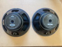
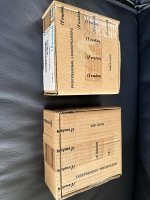
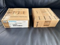
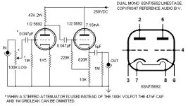
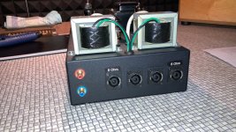
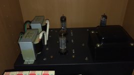
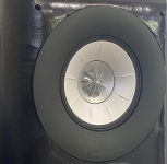
GRS 8PR-8 8" woofers (18 units, new)

Change of plans, just not going to work in our full time RV so need a new home.

18) GRS 8PR-8 8" woofers $159 plus shipping, OBO

NIB except one box opened to look at it, none every hooked up.

Willing to work out a deal on the shipping cost if possible.
Also interested in trades but I do not need much at this time.
I was going to order some Mark Audio MA200 drivers but might be interested in another model of MA drivers m in trade, part trade, etc
as I am building the Frugel-Horn Jain large version.

Thanks,
Rick

Show your transformer work (gallery)

Let's create this thread with the same purpose as the tube photo gallery thread, but about transformers. We can show off pictures, measurements, explanations, etc, mostly for fun and potential sharing of knowledge.
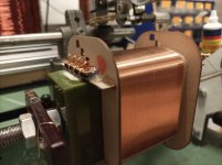
I'm starting with my most recent project of freshly wound coils, that are specially made for SE high Rp output stages with Rp ranging from 10k to 24k in series primaries and 2,5k to 6k with paralleled primaries.

Attachments

  • 30k Rp.jpg
    30k Rp.jpg
    148.5 KB · Views: 1,084
  • Secondary.jpg
    Secondary.jpg
    148.1 KB · Views: 1,099

More information about Gryphon audio equipment

Greetings all,
I was here for long time as a reader but recently I have purchased Gryphon audio system and I would like to know more about them.

System is composed of Preamp and a power amplifier.

1- Gryphon LE limited edition 91 of 100
2- Gryphon DM 100 limited edition.

I did some research but. I couldn’t find detailed reviews. Since these seem to be old models. Please if you know any information about the models like when was manufactured or specifics design criteria it would be great. By the way the system sounds fabulous in my room.

Thanks 🙏
Ahmed

Japanese 100V First Watt amps - run at 240V

I purchased a pair of SIT1 mono's from Japan, which are currently en-route to myself in Europe. I realize only now that Japan runs on 100V and not 120V.

I was planning to adjust from 120V to 240V via wiring the dual primary transformer in series.

I guess, with these Japanese amps, I won't be able to do so... WHOOPS!! Live and learn 🙂.

I suppose I need to replace with appropriate transformers? If anyone has the original AnTek part number that would be appreciated.

Note I reached out to First Watt directly some time ago with a similar question but did not get a response, therefore asking here.

Simulation of a 3-way speaker with a cardioid pattern

Hello everyone, I am trying to run simulations in Vituix, with the aim of creating a 3-way speaker with a cardioid pattern. I started by tracing the speakers from the manufacturers' websites, then applied the low-frequency loading and baffle diffraction using the various tools that Vituix offers. My goal is to replicate the speaker to see if I can achieve reliable simulations with what I have designed and measured.
I will post a couple of graphs to share the simulation results and perhaps get suggestions for improving the whole setup.
The speaker will be a stand-mounted design, with dimensions of approximately 40/45cm in height, 35cm in depth, and 20cm in width. The tweeter and midwoofer will be placed on the front panel axis, while the two subwoofers will be positioned on the two side panels.
The crossover will be active, and the goal of the project, in addition to evaluating the quality of the simulation, will be to attempt to simulate an active cardioid system using the two side subwoofers.

1742926985700.png

1742927034509.png

1742927097865.png


Many thanks
Stefano
  • Thank You
  • Like
Reactions: krivium and GM

bookshelf horn speaker for small room

After finishing my last speaker build i became interested in horn speakers. Especially the subject: horns/waveguides controlling early reflections in small rooms.

The Goal of the design is to provide good sound in a small room by lowering the amplitude of the early reflections, especially floor and ceiling reflections. Also, provide ample bass extension while limiting speaker size (Buchardt Audio S400).
The effect of early reflections is quite hard to deal with in small rooms, caused by the lack of flexibility in layout and space for room treatment.

I would love to hear your $0.02 on horn selection, LF driver selection etc. don't hold back!

March 14, 2025:
HF driver will be celestion cdx1-1747.
Currently working on the effect of the baffle on extending directivity to lower frequencies.
Evaluating directivity of RS180-8 on a baffle to match directivity with the HF driver.


Original text
For the HF i came up with the following combo:

Peerless XT25TG30-4 mounted on a no name constant directivity horn form Aliexpress. It measures 160mm x 160mm and has a depth of about 100mm.
After modeling the combo in AKABAK (without LEM, haven't figured it out) the following results are pretty good, IMO, for a 10 euro horn.
I already received the horns in the mail. Pretty thick material and a nice finish on the front. The flange to the driver is not that good. Its bumpy but fixable.

PS: the lines on the graphs are steps of 10 degrees. for the delay spectrum the color steps are in 5 dB.

Would this combo be any good and what would you use?

Attachments

  • Screenshot 2025-02-25 144007.png
    Screenshot 2025-02-25 144007.png
    334.5 KB · Views: 77
  • horn + baffle horizontal.jpg
    horn + baffle horizontal.jpg
    82.5 KB · Views: 36

Wharfedale Triton crossover

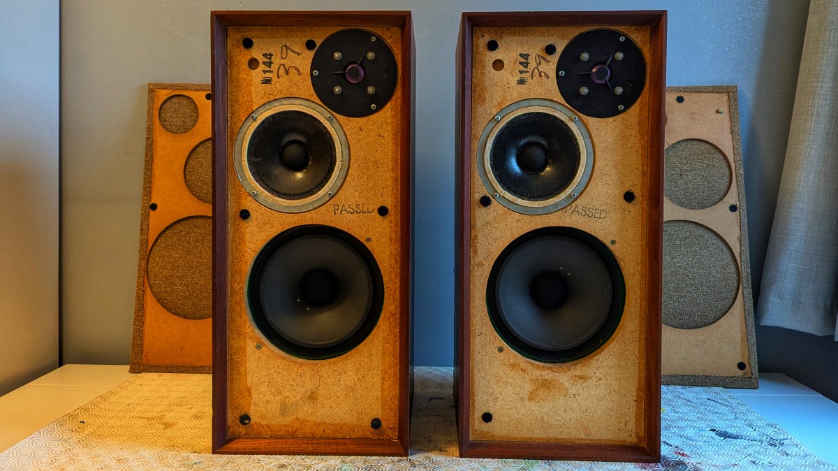
I recently purchased some Wharfedale Triton speakers off eBay, with the intention of refurbishing them as a learning exercise. Essentially a practice pair of speakers, to learn how to clean the grille cloth, rewire and re-cap, that kind of thing. They came with a captive speaker cable that was terminated with a two pin DIN plug. Without thinking, I just chopped those off, as the little amplifier I use to test things only takes bare wire. I naively assumed that there would be some +ve / -ve type marking on the crossover circuit board inside, which it turns out there isn’t.

Here's the speakers in question:
front-exposed.jpg


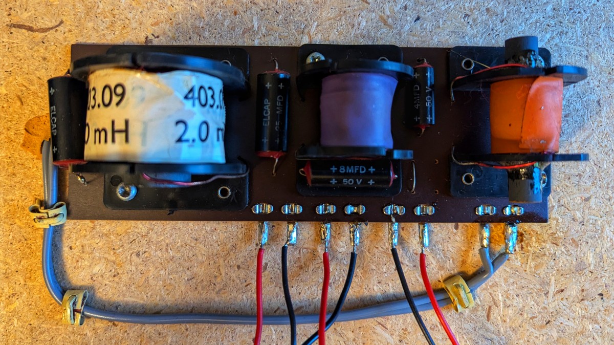
A top view of the crossover, note that two of the inductors are missing any indication of value:
crossover-top-view.jpg


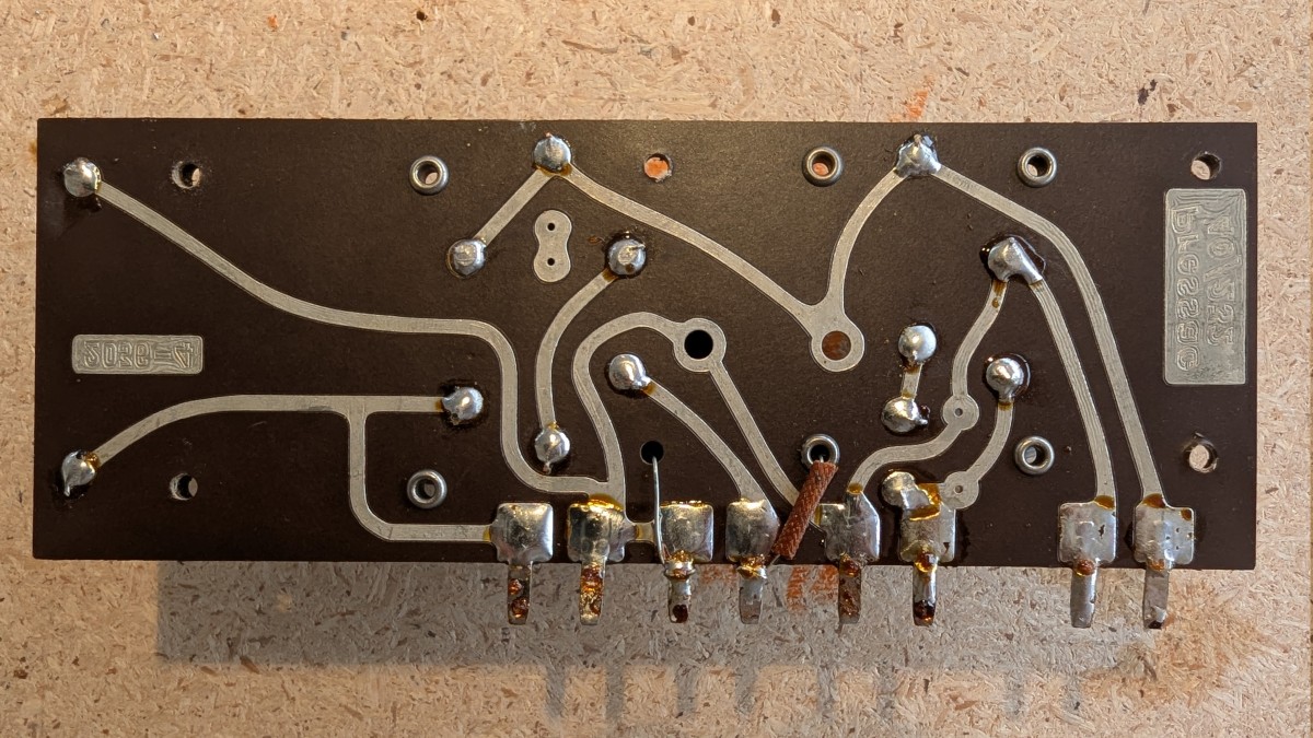
A mirrored view of the bottom of the crossover after I'd de-soldered all the leads:
crossover-bottom-view-mirror.jpg


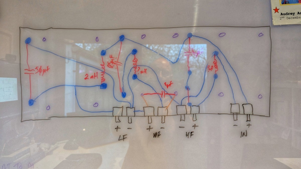
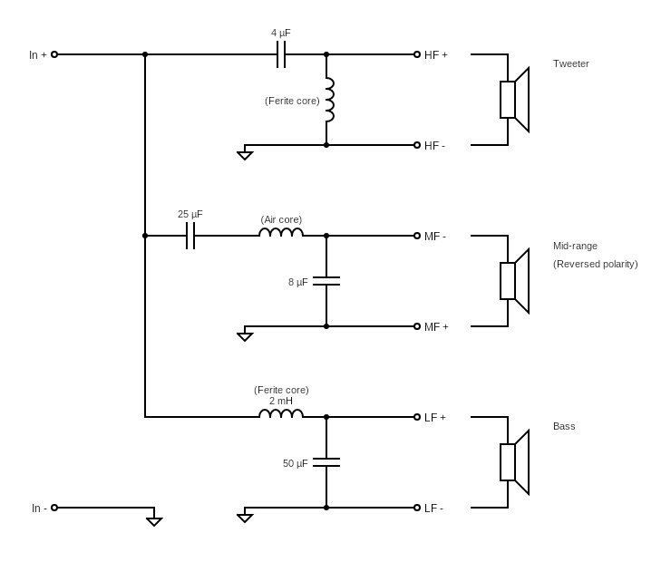
I took some photos and attempted to try and understand the circuit, so I could determine the correct pins to wire up to some proper terminal posts. I started on a whiteboard, then tried to convert that into a “proper” circuit diagram. I’m new to all of this kind of thing, and am not sure that I’ve used all the correct symbols and terminology on the diagram; I would welcome some feedback on that.

My whiteboard circuit:
crossover-whiteboard.jpg


And the resulting circuit diagram:
crossover-circuit.png


Could someone please confirm whether my circuit diagram is accurate…? Specifically, I would like to verify that I have correctly identified the positive and negative input terminals on the circuit board. That would be the right most tab being the positive input, and the one to it's left, being the negative input.

Cheers,

Bob.

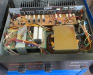
Inkel MA-920 help

Hi,

I just got this amp in very good condition. I liked its sound but I hear some noise when I close to the speakers (102dB sensivity) on both channels, even though amp specified as 105dB S/N ratio. I don't hear any noise from my Kenwood KM-106 amp (120dB S/N specified) with same speakers. Is this expected from such a big amp even though reasonable specs? or should I worried with something?

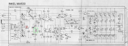
What is the purpose of the SVR114 pot? Is it for adjusting the DC offset which is around 10-15 mV on both channels.

Can I omit C108 NP dc blocking cap, (if the opamp offset is low) since there is another one (C110) next to it ?

Regarding the topology and the schematic, is there anything that can be improved? Any comments and suggestions?

Thanks in advance.

Attachments

  • MA920-inside.jpg
    MA920-inside.jpg
    396.8 KB · Views: 197
  • MA920-schematic.jpg
    MA920-schematic.jpg
    300.4 KB · Views: 153
  • Like
Reactions: hpavictor

UltraAnalog D20400 DATA ! I have it all !!

Yes, I finally have the application notes!

And the DEMO 1 eval board paperwork and of course the original datasheet which is readily available but this time in much better quality.

Where did I get them from? I asked Daniel Weiss if he had them after discovering his BW102 studio mastering processor used some in the 20bit DAC module.

So a BIG thankyou to Daniel Weiss! A very friendly and helpful man.. even though he's also a very busy man too.

I've uploaded them to PDFcast.org so they will be searchable on there in the future and here are the download links:

UltraAnalog D20400 Application Note AP02 (pdf)

UltraAnalog DEMO 20 bit ADC - DAC Evaluation Board Datasheet (pdf)

UltraAnalog D20400 20 bit DAC Datasheet (pdf)

Have fun with those people.. I will.

Keep a look out for D20400s in old 20bit pro equipment like Philip Drake broadcast gear, Weiss BW102 mastering processor 20 bit DAC modules - there will be others.

China 500w amp cutting out

I have been trying to get 2 china 500w amp boards to run in full bridge mode with a single supply of 160 volts.
Currently the grounds are connected between the 2 I will try floating each on its own as I can but I don't think that will fix the problem...any ideas? I'm thinking the ground is being modulated on the VAA VSS side causing a shutdown....this happen at fairly low volume.

Hi all!

Hello,

just signed up here, I've been reading and following some threads here for a while and really value the communities' input. I'm currently on a mission to revive my dad's NAD stuff (mainly an amp and CD player) which have failed and have been sitting in my mom's basement for years.

Next to that, I'm interested in building a set of speakers for my living room.

I have experience tinkering with and fixing stuff, sometimes with limited success, but I'm confident to give it a try. In the past, I've built transmission line speakers, a portable bluetooth speaker, a guitar tube amp (from a build kit), and fixed up some nice old studio headphones.

Looking forward to the discussions,
Cheers from the Netherlands, Felix

Experimental Distortion Matrix

Guitar Distortion Matrix

Here’s a circuit that provides a variety of distortion sounds for the electric guitar. The passive diode matrix should be driven by an active device, such as a volume-boosting stomp-box or guitar preamp, while the output can go to any kind of guitar-amp or other such active device. The design is based on the distortion circuit in a project called the “Mod Box” that appeared in Electronics Now magazine in 1997 (May issue, p. 45). And while the article is old, the circuit I designed based on it remains perfectly valid.

1743168531244.png


The preferred sounds, emphasizing even-order harmonics, with either the Fuzz, Buzz, or Overdrive settings is to activate only one diode oriented in a given direction but two in the other direction. It does not matter which directions are chosen for the combination as long as there’s an imbalance. Of course, any setting provides distortion. The germanium diodes, in the Fuzz setting, are said to give the most pleasing distortion, similar to that of a vacuum-tube clipping, while the silicone diodes give a harder sound, with the LEDs the brightest.

Because of significant loss of input signal level to achieve the distortion effect, some kind of active device, such as a stomp-box with extra gain, is needed on the input. Or, to turn this into an active project, battery-powered solutions are shown below. Use the preamp to drive the matrix and put the buffer between the matrix output and the input of an amplifier or other active device. And I recommend keeping the input/output jacks as shown, to allow for the greatest versatility, even if everything is put in one enclosure. For the +9V DC supply, connect the negative end of a transistor battery to ground so the positive end is the supply. And one battery will serve both circuits.

1743165035016.png


1743165060036.png


EOF

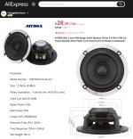
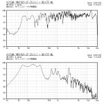
AIYIMA YM91R20-2F-ZXJ-L1 (3", full range)

AIYIMA YM91R20-2F-ZXJ-L1 (3", full range) installed in HB-07F-ML (double bass reflex).
It is a low-priced product, but it has a die-cast basket and neodymium magnet.
The sound quality is better than the price. Cost performance is high.

AIYIMA  YM91R20-2F-ZXJ-L1-04.jpg


Login to view embedded media

Attachments

  • AIYIMA  YM91R20-2F-ZXJ-L1.jpg
    AIYIMA YM91R20-2F-ZXJ-L1.jpg
    134.1 KB · Views: 389
  • HB-07F-ML-01.jpg
    HB-07F-ML-01.jpg
    185.7 KB · Views: 396
  • AIYIMA  YM91R20-2F-ZXJ-L1-05.jpg
    AIYIMA YM91R20-2F-ZXJ-L1-05.jpg
    110.5 KB · Views: 381

Pass XP-12 with FW F5

well today I moved aside a processor I've been using as a preamp with my F5
In went a 6SN7 buffer, noice! The dynamics suffered a bit in comparison but lower mids & bass were better resolved, tighter and deeper. The upper extremes were cleaner

I use to run a 300cx with a Pass Labs X1 pre, that was oh' so' yummy! Very little of my music collection sounded off, and this is the direction I want for my F5
Whats peoples thoughts on a Pass Labs XP-12 with an F5?
Has anyone used a Pass Labs preamp on their F5, if so I'd appreciate your findings please?

I'd rather buy a preamp as I already have another DIY project in the works.. 3 way 4 driver speakers for which I bought the drivers 15 years ago, Scan Speak & Focal

Thanks AL

waveguide for xt25 for crossing at 1 khz

I am working on a build from a slavaging a 22liter slanted baffle speaker cabinet, with driver xt25 and mw19p (or mw19tx)

I know this build is done to death and can reference troel‘s desgin however I want to spice it up having crossover frequency at around 1khz, to minimize the woofer directivty problem so the tweeter needs a waveguide. does any onknow the smallest waveguide i could use ? i am hopping something like a 4 inch waveguide or an elliptcal wavrguide to modify the exisiting 3 inch dome opening in the cabinet

Need some help decorating my music room

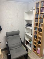
Hello, I have a interest and nostalgia for vintage hifi from the 80s and 90s, I don't have all the space in the world but a small room of 2 x3 meters. You have to make the best of what you have, right? But need some tips and ideas on how I can decorate this room?

I have a thought about replacing the white shelf with one that is a little deeper to have the hi-fi on display is it a stupid idea? But all thoughts and ideas are welcome with thanks

Attachments

  • IMG_0123.jpeg
    IMG_0123.jpeg
    756.5 KB · Views: 67
  • IMG_0122.jpeg
    IMG_0122.jpeg
    855.3 KB · Views: 70

Quiet PA amps

I use my PA system as my home HI-FI and so have an interest in any PA amps that are close to silent. Also in many situations even in PA very noisy fans can be audible for some music genres. I thought it might be informative to share a list of amps that are both powerful and do not make excessive noise. An amplifier can be classified as quiet as long as the fan noise is not audible from 2m away during light usage. I'm not very keen on modifying amplifier cooling unless airflow capability is retained.

Not Quiet:
Behringer Inuke
Cloud VTX series.
Ecler pam 1400 power amplifier
Powersoft Duecanali 5204
Powersoft X4 (Can hit 80dB/1m, so noisy it could even be a problem for some PA use)
Crown XTI series.
QSC RMX
Peavey IPR1600
MC2 amps (not sure on specific models)
Classic crown Macrotec MA5002VZ ETC. (Macro-Tech 3600VZ notable mention)
BSS EPC780
Crown I-tech 5000
Nady XA-900
Gisen K21x4 (and probably Soundgear Saturn 16 as it looks identical)

Not a total racket:
Powersoft Duecanali 1604
Samson S2000 2*650W@8 ohms 2*1000W@4 ohms, 2000W bridge
MC2 MC series
Crest CLh5000 (2*1470 watts 4 ohms (tested to far more on single channel))
Crest CA9 (the CA2, CA4 and CA6 should be about the same in this regard)
QSC Powerlight 2 series.
MC2 Txxxx series

Quiet fan:
Peavey CS800s
Yamaha Triple E series of amps(P, PC-1N, XP) E.G Yamaha PC9501N ~2*1500W 4 ohm
Yamaha P7000s (fan does not spin normaly, 2*1100W 4ohm - conservative rating)
Lab Gruppen E-series (2*200W 2/4/8/16 ohm)
Carver PM700 240W@8 ohms 325W@4 ohms (fan inside unit)
Samson SX-2800, 2*700W@8 ohms, 2*1000W@ 4 ohms, 2000W bridge
QSC USA 700, 2*240W @ 8 ohms, 450W@ 4 ohms, Bridged 900W
IMG STAGELINE: STA-2000D/STA1000D (fan does not turn on in normal use upto ~85C?) (upto 4*500W, 4ohm)
Speaker Power SP2-12000-DP (2*6000W, 2ohms)
Crown XLS DriveCore 2 Series (up to 2*775, 4Ω (XLS2502 )) (fan does not turn on in normal use, multiple reports)
Dynacord SL Series (up to 2*1200W @ 4Ω (SL 2400))
Crown CTS4200 (4*260W 4ohm), (fans don't spin on my unit at idle - others report differently there may be firmware differences)
the t.amp TSA 4-300 4*550W (4ohm)
lab Gruppen C series (passive under low load)
Crown CDi1000 (2*968W 4ohm, fan does not spin under light load however once fan spins its quite noisy)
QSC EX800 does not run its fan until it gets hot (2*325W into 4ohm)
MC2 Delta 20 (4*350W 4 ohms - unit can have internal link changed to force fan to run at low speed but may thermal power limit as a result)
Powersoft Mezzo 6 series (up to 2*300W 4 ohms)
the t.amp Quadro 500 DSP (4x 500 W at 4 Ohm, 4x 250 W at 8 Ohm)

Fanless:
Extron XPA amplifiers (upto 400w per channel, 800w bridge - lots of models, PSU has slight hum in my second hand XPA 1002)
Apart audio champ 2, 2*(180W 4 ohm, 120W 8 ohm)
Apart audio PA2120, 2*(120W 2/4/8 ohm, Small amount of mains transformer mechanical hum audible in silent room)
Stewart world 600 (2*190W 4 ohm)
Stewart world 1.2 (2*350W 4ohm)
Behringer A500 (~2*200W 4ohm)
Behringer A800 (2*250W 4ohm)
Crown K1/K2 (upto 2*1250W 2 ohm)
QSC 3500 (2*560W 4ohm, 2*700W 2ohm, possible transformer hum)
Samson Servo 550 (2*275W 4 ohms, 1*550 watts into 8 ohms (bridged mono mode) , runs hot when pushed)
3e Audio EAUMT-0140-2-A (TPA3251 based) (2*128W 4ohm)
Powersoft Mezzo 3 series (upto 2*160 W 4 ohms)
QSC SPA series (upto 1*400w into 4/8ohms in 1/2 rack space)
  • Like
Reactions: stoneeh and mrk7

Electrocompaniet EC-3 and ECMC-1, schematics wanted

Dear all,
I am looking for schematics from mentioned Preamp and Step-up board. Main pre is working OK, with Line inputs, but phono one have problem. Since ECMC-1 is a step-up board, I cannot check it either. I contacted mother company but they told me it is not in their policy to share such service information...
I would appreciate if someone has drawings (is OK in scan or photo) to help me out to repair it.
Best regards,

John

Tear down my three-way driver selection

Background: I've successfully built a passive small 2-way paired with a DIY under-bed subwoofer. Next project (with no particular hurry or deadline) is a pair of 3 way bookshelves inspired by Troels' Bookshelf-3WC. Really just borrowing the driver alignment. Would like to make the cabinets sealed rather than ported but if I need to port to get down to ~40hz I will. Speakers will be on a literal bookshelf surrounded by books.

This will be a hybrid active/passive, active DSPed crossover for the woofer to mid/tweeter, and passive between those. Aiming to cross over between woofer and mid at <200, and to the tweeter over 7k. System will be for casual listening in a library, aiming for a wide listening area rather than a sweet spot, and will not be played loud.

So far these are the drivers I'm looking at. But this is where my expertise flags so really let me have it.

Woofer: Dayton RS225P-8A
Mid: TB WS-2143
Tweeter: Dayton ND25FA-4

The woofer I've used before in the bedroom sub and like it well enough there, and in this application isn't having to take on the midrange.

Threshold FET One Series II E/series version

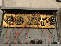
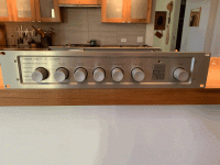
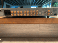
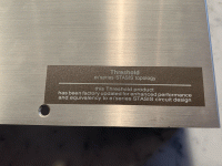
Today I purchased a beautiful Threshold setup locally, including an S/300 Series II amp and a FET One Series II. Both units have a sticker that indicates they've been factory updated to the e/series STASIS topology. I bought them from a local audio dealer who bought them from the original owner.

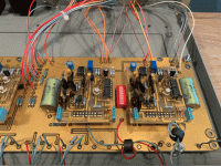
The preamp has jacks for the MC inputs, but the MM input is blocked off. Inside the preamp, the circuit board looks very different from other photos of FET Ones I've seen. Mine is more similar to a FET Nine I've seen a photo of, with little daughterboards attached to the main board, which presumably host the preamp circuits. The phono preamp boards have a DIP switch nestled between them, which, if it's similar to the FET Nine, allows different impedance and capacitance settings to be selected. But I haven't managed to find a manual for this particular mod of this preamp. Do any Threshold experts here have any insight to the switch positions for the FET One Series II with e/series mod?

I've attached a couple of photos of my unit. Thanks for any help!

Attachments

  • tempImageJavtex.gif
    tempImageJavtex.gif
    1.5 MB · Views: 421
  • tempImageQaZIsv.gif
    tempImageQaZIsv.gif
    1.2 MB · Views: 179
  • tempImageJViXuy.gif
    tempImageJViXuy.gif
    1 MB · Views: 169
  • tempImagefCRnGS.gif
    tempImagefCRnGS.gif
    1.6 MB · Views: 219
  • tempImagex4rVnj.gif
    tempImagex4rVnj.gif
    1.6 MB · Views: 287

Long time Lurker, first time poster!

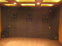
I have been doing off-and on DIY audio projects since the 2000s. First one was and IB subwoofer cut into my attic in ~2005 with 4 Dayton audio subwoofers. Later on built a 7.3 home theater system with modified Econowaves built into a baffle wall.
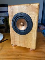
Did nothing for years. Recently built a pair of desktop speakers with the Mark Audio Pluvia and some pieces of firewood. Next projects I am planning are some 18" subs and TAD 2404 clones, and some 15" OB speakers.

Attachments

  • baffle wall 2 006.JPG
    baffle wall 2 006.JPG
    250.8 KB · Views: 20
  • markaudiospeakers.jpg
    markaudiospeakers.jpg
    595.6 KB · Views: 18
  • Like
Reactions: birdbox

Advent Maestro speaker question

I've got a pair of Advent Maestro speakers that were given to me today. They are in good condition and the woofers were refoamed a few years ago.

I already ordered new caps for the crossover.

Two things I've noticed.

1. The speaker wire terminals on both speakers has separated from the terminal cup with the crossover on it at the bottom. What should I use to secure it back down?

2. I've read where the woofer doesn't play high enough causing a hole in the frequency response near the crossover point of the woofer and midrange which is 900Hz. Listening to them, I believe I actually hear that, but will wait until the film caps come in and are installed to see if that fixes it. If I still hear the issue, what is the best way to eliminate the issue? Normally I'd just use a different inductor value for the woofer, but the inductor is part of the dish where the fuse, speaker terminals and other crossover components are and I'd have to add an inductor which would require mounting it somewhere in the cabinet.

What I should do is disconnect a midrange and test it using my DATS V3 speaker tester so I can see what the impedance of it is as in order for the 14uF cap value to be correct the midrange impedance would have to be 12.5 ohms provided the specs I found are correct. That's not exactly possible though given the speakers are at work now.

Specs of the speaker.

https://audio-database.com/ADVENT/speaker/a-1012.html

Also I will run these with a powered sub.

The response is +/- 3dB 42-23kHz

I currently have the powered sub crossover set to 40Hz, but am not that happy with it.

I can put two 160uF electrolytic caps in parallel to make a 320uF cap which based on the rated 6 ohms impedance of the speaker will give me a high pass of 82Hz.

I might try that tomorrow with the caps between the + speaker lead and + speaker terminal. If it sounds better then I may install the caps between the + speaker lead and woofer inductor (when i install the film caps) so that I don't run the risk of the caps affecting the midrange and treble.

EDIT:

Here's the crossover schematic I found.

Advent Maestro crossover.jpg


However the response graph I found seems to suggest there is no hole in the frequency response.

FU0X2OTJ7S1LJXG.png

Another realization of Bob Cordell's THD Analyzer

Hi all,
I started the adventure to build Bob's THD Analyzer.
I made new PCB for my implementation.
They are: one for Sine Generator and Output Attenuator with the connector for the switch capacitors range board.
The cap sw PCB for Sine Gen, and Filter range (two equal for both).
One for Filter, Amp and Freq Detect.
One for Output Filter with connector for the Meter
One (little) for Meter circuits. Mount AD536AH for RMS conversion
One for Input Attenuator/Amplifier
I still have not decided how to switch the resistance of the frequency, probably Optofet or Photoresistors but they latter have serious problems of thermal drift.

....le first photos

Attachments

  • THD SINE PCB (Small).JPG
    THD SINE PCB (Small).JPG
    63.5 KB · Views: 2,624
  • CAP SW PCB (Small).JPG
    CAP SW PCB (Small).JPG
    62 KB · Views: 2,530
  • THD FILTER AMP FREQ DETECT PCB (Small).JPG
    THD FILTER AMP FREQ DETECT PCB (Small).JPG
    70.5 KB · Views: 2,513

Hafler Iris Preamp remote control issues

I have a Hafler Iris Preamp, which I love. Probably will need a re-cap soon, but working well right now. Managed to find an Iris remote on eBay. Yes, my Iris preamp has the receiver board.

However, when batteries are put in the remote itself, the red tally light simply keeps on flashing (about 2x/second) and there is no response from the preamp to any button pushes on the remote. I believe the rcvr board in the preamp is functional, as apparently if there are issues with it the preamp won't come out of muting.

I've tried IR detection using the camera on my iPhone and there's no apparent flash from the remote. I've confirmed that I do see flashes from a known functioning remote.

Any ideas on where to start? I'm also asking on AudioKarma, as well as checking in on D. Hedin's thread here on making your own Iris remote in case mine can't be revived.

Thanks in advance!
Waldemar

Directivity study- polar maps of HF, MF and LF drivers in cabinets

I've posted a small study comparing High, Medium and Low Frequency drivers in a variety of cabinets.
It's on another forum that allows me to edit/amend as more data becomes available.

First up, some pretty colors:

Edit: Feb 2025- Speaker colours explained;

SPEAKER 3...
1738748489604.png


1738748520080.png


Normalised:


1738748564754.png


1738748537382.png


SPEAKER 3:
3 way speaker with twin 12” woofers in 13.75" wide, MT cabinet 9.5" wide with 6” midrange + 1” ring radiator offset from centre, no roundovers,
2.83V input applied:
Reference:
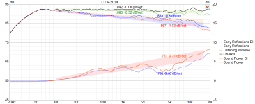
1738748654887.png1738769562347.png


SPEAKER 2:

1738746193359.png


1738746175399.png

Normalised:
1738746118907.png

1738746154924.png


SPEAKER 2:
3-way speaker with 8” woofer in 21cm wide cabinet with 1" roundover, and 5”/1” coaxial driver,
2.83V input applied.
Reference:
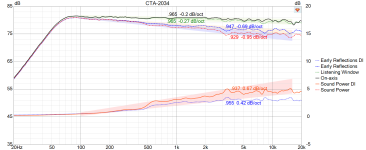
1738746261596.png1738769519075.png

Now, if you're not sure of how what these colors/shapes mean, then this directivity study is for you!
It's aimed at bringing you along the journey of speaker designs which have with smooth frequency responses in many directions.
If you are familiar with seeing a single on-axis (or a few off-axis ) measurements for loudspeakers, please have a look at this study to observe how off-axis measurements varying over a larger span eg. up to 360° horizontally and vertically may add value to your designs, and how the use of non-normalized polar maps may assist.

My study incorporates-
1.High Frequency devices includes dome tweeters, ring radiators, ribbon tweeters, compression drivers, in cabinets with and without round-overs, with or without waveguides/horns, or even without cabinets (nude).

Start at the top for a background/explanation
Jump straight to posts for non-normalised polar maps (horizontal 0 to +/- 90 ° minimum; 0 to +/- 180 ° horizontally and vertically where/when available):
All drivers highlighted in bold type are by fellow DIYers who kindly offered their data for our perusal / interpretation.

A model of a theoretical 3/4" flat piston tweeter on a 5 1/8" wide baffle with large 1.5" round-over
SB Acoustics SB19ST-C00-04 a 3/4" soft dome tweeter on a 5 1/8" wide baffle with 1" round-over
SB Acoustics SB29SDAC on a 8" wide baffle (coming soon)
Scan-Speak D2604/8330-00: 1" soft dome on a 8.5" wide cabinet, offset 1/2" from center line
Scan-Speak R2604/8330-00: 1" ring radiator in same cabinet, again offset 1/2" from center line
Fountek NeoCD3.0 a 8x60mm ribbon tweeter on a 8.75" wide cabinet with 10mm round-over courtesy @DcibeL
Fountek NeoCD3.0 on a 11.5" wide cabinet with 3/4" round-over courtesy Curt Campbell and @jholtz
Fountek NeoCD3.5H a ribbon tweeter & integrated horn on a 8.5" wide cabinet with 3/4" round-over, courtesy Göran @gornir
Fountek NeoCD3.5H nude (not mounted on any cabinet), courtesy @Juhazi
B&W HF00963 in tapered tube hard dome tweeter in a minimal baffle/tapered cylinder, courtesy @PKAudio
Tymphany DFM-2535R00-08 attached to a SB Acoustics H225 and H250 constant directivity horns, both nude
Tweeter of SICA 5-5-C-15-CP coaxial driver, mounted in 7" circular frame with 1/2" round-over, courtesy @vineethkumar01
Tweeter for SB Acoustics SB17CAC / SB17NBAC coaxial prototype courtesy @5th element
Tymphany XT25BG60-04 in Visaton WG148R waveguide, mounted on 11" wide baffle with 1.5" round-over
Various tweeters in courtesy @augerpro's waveguides mounted in real cabinets, with or without round-overs (including SB26CDC in 6.5" elliptical waveguide, Peerless OT19NC00-04 in 8" elliptical waveguide, horizontal measurements), Donate!
SB Acoustics SB26ADC in a customized 8" waveguide for 60° beamwidth from 1K to 12KHz. courtesy @fluid
tweeter from KEF R series (non-META) coaxial, mounted in a cabinet with 1.5" round-overs
tweeter from KEF Blade Meta/Reference Meta, mounted in cabinet with 1.5" round-overs vs no round-over (awaiting cabinets)

2. Medium Frequency devices includes cones and domes, typically covering 3-400Hz to 3-4KHz
B&W 5" FST midrange in 8.75" wide cabinet with r10mm round-over, courtesy @DcibeL
Larger 6" FST midrange in 9.5" wide cabinet and 8.5" spheroidal cabinet
previous generation (Kevlar) 6" FST midrange in the same 8.5" spherical cabinet
Volt VM752 3" dome midrange in 14.5" wide cabinet, offset 1 11/16" from center, courtesy @mbrennwa
Faital 4FE42 4" cone midrange in a 6" spheroidal cabinet

Purifi 5" and 6.5" drivers on same width baffle (completed, awaiting publication)
Purifi 6.5" aluminium vs fibre cone


3. Low Frequency devices includes woofers and/or subwoofers, typically covering 3-400Hz and below:
KEF LS60 's dual 5.25" woofers, side firing, in dual opposed configuration, rear ported courtesy @bikinpunk
KEF Blade 2 Meta's quad 6.5" woofers, in dual opposed configuration, 2 on each side panel, with rear firing ports courtesy @bikinpunk
KEF R11 Meta, quad 6.5" woofers, all 4 on front panel, with rear firing ports courtesy www.audiosciencereview.com


Thanks again to all those involved who kindly supplied their measurements.
If you find anything that you feel is a misrepresentation of your data, please let me know.
All constructive comments welcome, as well as suggestions for better readability. It's a lot of graphs, I know.

PS. If a link is currently unavailable; then it is currently being updated/edited. Try again in 24 hours. Thanks for your patience.


Speaker 1...
A Cheap thermal IR camera for troubleshooting power amplifiers

I've been working on an old power amplifier (SAE MK3CM) that has a problem with one channel. It works OK for a short time and then the positive side of the output waveform starts to clip, somewhere around 5V. Most of the voltages measure reasonably close to what the SM says they should, but one clue is my nose. I can smell something getting hot. So I decided to make myself a thermal IR camera to determine what's getting hot w/o burning myself or potentially connecting my body to up to 150V (the supply rails are +/- 75V).
I found a relatively inexpensive IR camera that has a 32 x 24 pixel array, the MLX90640. Sparkfun and Adafruit will sell you a board with one on it for about $70 -- and that doesn't include the display and Arduino-ish board needed to process and display the thermal image. However, I already had a Teensy 4.0 and a 320 x 240 TFT display so I just bought the camera chip from Digikey. The camera only has 4 pins -- Vcc, ground, SDA and SCL -- so I just soldered it down to a piece of perfboard.

Adafruit has some example programs for their version so I downloaded them and modified one for my particular display (it has about 4X the number of pixels than the one they use). And it works surprisingly well. So I cobbled together a setup to view the component side of my power amplifier and did find significant differences between the two channels. So here are a few photos showing my admittedly crude setup:

ThermalIR-1.JPG

The above photo shows the display. The camera is attached to the tripod using a "C" clamp with some scrap 3D printing failure I had lying around. The amp is shown in the lower right side.

ThermalIR-2.JPG

Above you can see the Teensy 4.0 and a better shot of the camera. The camera chip actually is on the bottom side of the board, because I installed it upside-down....oops...
ThermalIR-3.JPG

The above image shows what the "good" side of the amp looks like, thermally speaking. The two hot spots are two cascode-connected transistors whose inputs are the front-end LTP's. In normal operation they should dissipate about 76mW.

ThermalIR-4.JPG

This is a photo showing the faulty channel. At least one of the transistors -- which happens to be associated with the positive side of the output waveform -- clearly is running hotter. So I have narrowed-down my search by quite a bit. BTW, my hand, which is around 80F, only generates a yellow color so the hot spot is pretty warm.

One initially-challenging problem was figuring out just exactly WHERE those hot spots are. I tried using my finger to point at the hot spot but it was just too big. So I made a hot spot "wand". Just a 120 ohm 1/4 watt resistor taped onto the end of a wood dowel. I adjusted the power supply driving it so it doesn't overload the camera. And here's my high-tech "hot spot":
ThermalIR-5.JPG

Making a Hafler IRIS remote control

I was recently gifted a Hafler IRIS pre-amp (along with a DH-200 amp). Unfortunately it does not have a remote control.
Remotes are rare and expensive. In addition one requires the internal receiver board. Cost could be $120 or more if I could find them.

I have studied the IRIS schematic and have decided to roll my own IR remote control.

My plan is as follows.
I'll be using one of these remote kits for arduino.
https://www.ebay.com/itm/373765651681

I will then interface this to an Arduino Pro micro (5v version)

I only plan to implement volume, and input selection at the first go. But I may add balance and normal/mute functionality later on.

Below is what I have figured out so far regarding the interface from the IR receiver board to the pre-amp. This connector is on the back of the display panel of the unit.

In addition there is a transparent window where the receiver phototransistor would mount near the connector.

I will mount the Arduino board on perf board and there will be an LM324 to translate the D/A output of the Arduino to create the volume/ balance 0-14v control voltages.

There will also be some 5v to 16v logic translation for the input mux and other control signals.

My first experiment will be to hook up some potentiometers and dip switches to see if I can fake the operation manually.
I will post progress in this thread. All comments and suggestions welcome.

Wish me luck...


Hafler Remote connection

Pin Name Notes
1 JAM I believe JAM is used to lock input selection when recording.
2 RMB 0-14 volts for balance setting from remote
3 RMV 0-14 volts for volume setting from remote
4 REM V/B Active high pulse to set volume, active low to select balance
5 Neg16v
6 NORM Active high pulse to select normal remote
7 MUTE Active high pulse to select mute remote
8 WARN ??
9 Pos16v
10 GROUND
11 N/C
12 I2 "C" select for Input MUX
13 I1 "B" select for Input MUX
14 I0 "A" select for Input MUX
15 I3 Believe this is pulsed high to latch the LED indicator for input and latch selection

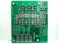
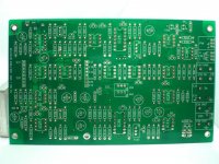
What happen to LC Audio Technology? Acquisition by an other Company?

What happen to LC Audio Technology ? Acquisition by an other Company ?

Very interesting ideas were always realized here.
Some examples:

Millenium Amp
https://www.octave-electronics.com/lcaudio/temil.shtml
https://web.archive.org/web/20011214001242/http://www.lcaudio.com/temil.htm
https://web.archive.org/web/20011110044633/http://www.lcaudio.com/millmateng.PDF
http://www.diyaudio.ru/filestore/Millenium_-_cookbook.pdf
https://www.diyaudio.com/community/...m-xp-help-if-possible-from-lars-clause.75711/
https://www.diyaudio.com/community/threads/end-millenium-amp-opinions.167/

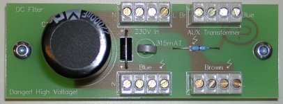
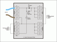
DC-Filter
https://www.hifisentralen.no/forumet/classifieds/lc-audio-dc-filter.106920/

Low Noise Regulator
https://www.diyaudio.com/community/threads/improving-on-lcaudio-lownoise-regulator.45451/
http://mihalcz.ingyenweb.hu/keret.cgi?/other/ulnreg.html
https://www.diyaudio.com/community/threads/ultra-low-noise-regulators.337183/

Dual Mono RIAA
http://www.audiofilo.com/esp/lcaudio/Sidewinder.htm
https://www.diyaudio.com/community/threads/lc-audio-dual-mono-riaa-light-mc-headamp.210506/

Line and RIAA Stage Upgrade with AD825 Operational Amplifier
https://www.octave-electronics.com/lcaudio/ad825.shtml
http://www.audiofilo.com/esp/lcaudio/Sidewinder.htm

LClock XO Precision - CD Master Clock Generator
https://www.tnt-audio.com/accessories/lclock_e.html
https://www.diyaudio.com/community/threads/masterclock-help.167512/

ZAP Filter
https://www.octave-electronics.com/lcaudio/zapfilter.shtml
https://www.diyaudio.com/community/threads/zap-filter.8837/

Class-D
https://www.diyaudio.com/community/threads/new-module-by-lars-clausen.80526/
https://ing.dk/debat/hjemmebygget-hi-fi-forstaerker

Overview:
https://www.octave-electronics.com/lcaudio/lcproducts.shtml

Under some online portals and websites from suppliers is LC Audio still to find - go to
https://hifi-products.com/L-C-Audio-Technology-ApS-manufacturer-475.html
and
https://www.octave-electronics.com/newadd.shtml
but the website itself no longer exist since approximately two years - go to
http://www.lcaudio.com

Who know the currently company name for no longer exist company LC Audio Technology ?
Thank you for an information.

P.S.: Please note that this is not about this manufacturer for loudspeaker drive units:
https://audiotechnology.dk

Attachments

  • dcfilter.jpg
    dcfilter.jpg
    102.9 KB · Views: 191
  • dc filter with tranzorber.gif
    dc filter with tranzorber.gif
    8.7 KB · Views: 176
  • ZAP filter.pdf
    ZAP filter.pdf
    45.2 KB · Views: 104
  • xo3-7s.jpg
    xo3-7s.jpg
    18.9 KB · Views: 180
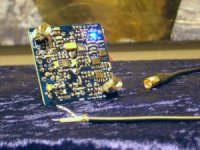
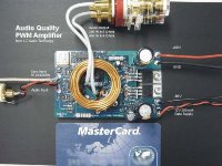
  • PWM amp module.jpeg
    PWM amp module.jpeg
    35.7 KB · Views: 217
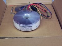
  • zp3trafo.jpg
    zp3trafo.jpg
    390.1 KB · Views: 174
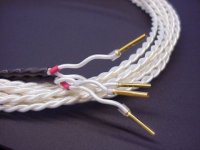
  • teflar2.jpg
    teflar2.jpg
    22.4 KB · Views: 163
  • SoftStartBot.jpg
    SoftStartBot.jpg
    9.9 KB · Views: 164
  • SoftStartTop.jpg
    SoftStartTop.jpg
    18.5 KB · Views: 183
  • RIAA Dual Mono.jpg
    RIAA Dual Mono.jpg
    63 KB · Views: 178
  • LClock XO.jpg
    LClock XO.jpg
    32.5 KB · Views: 171
  • lclpic1.gif
    lclpic1.gif
    30.9 KB · Views: 160
  • ad825 modules.jpg
    ad825 modules.jpg
    32.6 KB · Views: 165
  • millmateng.PDF
    millmateng.PDF
    2.1 MB · Views: 139
  • LC audio overview.pdf
    LC audio overview.pdf
    2.9 MB · Views: 163

Adding a second woofer to the speaker system

I've successfully created three-way bookshelf speakers containing a 10" woofer, a 2" dome midrange, and a 1" tweeter per closed enclosure for years. The crossovers are tuned to have output response (nearly) summing flat as shown in this picture.

3-way.png


However, I've been using them with an active subwoofer. Now I plan to stop using subwoofer and would like to listen to low-frequency from the main speakers. I removed subwoofer and found the bass wasn't enough, though I reckon these speakers sound flat.

I still have a pair of the woofers unused so I thought to add them to the system. In other words, the bookshelf speakers will be converted to floor-standing from now on.

The problem is I cannot easily add them without mod the crossovers. And I want to increase only low-frequency region. I finally need to convert them to 3.5-way system. In fact, I tried building them 3-way by typical way of adding the second woofer and redo the whole crossovers and found the unsatisfied result when there's no upgrading in bass SPL increasing anymore. Thus, I realized the 3.5-way system may correctly fix the problem.

Here is the simulation of the 3.5-way system that I randomly generated in simulation software.

3.5-way.png


I confess I don't have knowledge about the procedure or theory for building 3.5-way system. I simply add a second woofer with twice larger inductor on it, the 14mH coil.

And this is the comparison between 3-way and 3.5-way systems.

comparison.png


I would like to ask whether I did it correctly? And is the result (simulation graph) acceptable? I know the more accurate version should be from real measurement not simulation result, but this is the first step of learning. So, please try to understand.

Need help designing a simple flip flop for 12V trigger

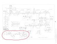
See the attached circuit circled in red. The circuit senses a signal and provides -12V for on and +12V for off, just the opposite of ICEPower modules. I am wanting to have the circuit provide +12V for on and 0V for off. A little more complicated than a simple flip flop. Any ideas? I can build a simple circuit on a breadboard and piggyback off the +-15V to power it.

Scan20250326134244.jpg

Quatre QMI Gain Cell Series Amps

Hello, not sure if this is the best place to seek answers but this forum popped up as an option when searching the net for info about Quatre Gain Cell Series Amplifiers. Want to know how to approach powering them up for the first time in probably 6-10 years. One is a DG250C and the other a GC500 the internals in both look fairly clean although showing signs of possible repairs or up-grades... etc, and both look like fairly substantial pieces of gear with one (GC500) having the most enormous power transformer I’ve ever seen on any piece of music gear to date period. A friend of mine got them out of a storage room in a club where they were once used as the house dance pa system and I don’t even know if they work or not. Given the nature of the situation it would seem reckless to simply load the speaker out’s and just plug it into the wall due to the size of the capacitors and the adjacent delicate looking pc boards with small chips standing off the board.

I’m hoping that I could use these (or one of them) for an alternative s-state system in my home as I do enjoy the clarity and POWER of a good s-state amp as an alternative to several tube amp sound systems that I currently own and rotate periodically. I had to sell my last good s-state power amp about a year ago due to relocation cost and I miss it. It was a JBL/Urei 6260 power amp and I used it mostly to power my Altec Valencia’s that also had to go about a year prior. Anyway… enough sob story telling. Any advice on these amps? Things I should know? Like, how to control the levels as there aren’t any on the amps themselves?? And the safest way to test power them up would be greatly appreciated. Again i have 2 amplifiers… Quatre Gain Cell Series DG250C QMI and GC500 QMI.

Also: I'm a diy-er that probably should have been on this forum a long time ago and looking forward to sharing ideas and learning more about how to tweak, mod and make usable circuits.

Thanks!

Asathor - a JBL 4367 Clone

attachment.php


Hi Guys!

I have always been fascinated by the large monitor speakers from JBL. Unfortunately, these are not cheap, so I wanted to build something like the 4367 myself.

http://www.newaudio.it/JBL/4367 JBL (1)/JBL Synthesis 4367 White Paper.pdf

15 "plus compression driver / horn was given. So I started looking for suitable drivers.
My friend Nico Germanos from Quint-Audio, Germany gave me the tip to test the new Tymphany DFM drivers and sent me a pair.
Since I don't have many horns to test, I immediately sent the drivers to my DAU buddy Christian. A few days later he sent me the measurements on the Monacor MRH-200 and I was amazed. Nico was right, the Tymphany DFM-2535s run great.

attachment.php


Since the MRH-200 is quite expensive, I decided on the almost identical Celestion H1 9040-P, which costs only a third.

Now I had to find a suitable candidate for the bass. Since the DFM is quite cheap despite its great measurements, I wanted to stay in a similar price range in the bass as well. Together with my friends from the DAU we discussed many possible woofers, but most of the cheap ones needed too much volume for bass reflex. In the end it was the LaVoce WSF152.50, which was kindly made available to me by the German distributor Steinigke Showtechnik.
This woofer runs very well in a closed box, which is brought to a lower cut-off frequency by a high-pass cap. Not super deep, but it will work well when the speakers placed close to the walls.

attachment.php


Both drivers are very well made for this price range. Since the Tymphany and the horn are smaller compared to the drivers in the JBL 4367, the crossover frequency is higher than in the original. I ended up at around 1500Hz.

attachment.php


The box also works very well at 15, 30 and 45 degrees horizontally off-axis (2db offset).

attachment.php


The crossover is an 18db high pass and a 12dB low pass plus serial notch.

attachment.php


The cost in Europe is less than 500 Euro for a complete pair. Certainly not much for a loudspeaker that has a surprisingly good sound and can also manage very high levels without problems.

If you want to see more designs from our small diy-group, please visit our german homepage:
Presenting DIY-HiFi Projects - The Idea behind It! - Der-Akustische-Untergrund

:cheers: :wave:

Octal Line Stage from Vacuum Tube Valley no11 - Thoughts on Film Caps in the Power Supply?

Greetings, Friends. I was looking at some scans of the old Vacuum Tube Valley magazine and ran across their Octal Line Stage, posted in Issue 11, Spring 1999.

VLV OLS AMP.png


VLV OLS PS.png


I'll include the entire article at the end of the post.

It's a nice looking circuit, a cathode follower.

Looks like the 100k volume pot is acting as the grid leak resistor, don't love that. I'd add a 1M from Pin 4 to Ground.

And I guess that's a voltage doubler (?) to make 12v to allow 12S_7 tubes, don't think I'll use that. Might run the tubes on AC to start, or use a bridge rectifier with 1N5820 and CRC to make 6.3vDC.

I'd like to use some of those Vishay film caps that are so cheap now. C1 in the power supply is much too large, even with the low current demand. I'd go with 20uF, and this cap from Vishay looks very nice at $8. The 2nd cap in the power supply is spec'd at 100uF 450v, a very affordable EL cap but a rather expensive film cap. Could I use a lower-value film cap in this position without impacting the performance of the preamp?

The cap in the amp circuit is very large, 330uF 450v. The best option here from Mouser is an Audio-grade EL with a rather short lifespan. Could I use another of those 20uF film caps? As there's no film cap option for the bypass cap (330uF 35v) I'd probably use an audio-grade EL for that, and just plan to replace both caps after 2000-ish hours.

Thoughts? Thanks for taking a look!

w

Attachments

Hello All

My new to the forums post. I’ve actually read many discussions on this forum before but never as a member. I’ve been an electronics enthusiast for pretty much my entire life (over 40 years so far). I’m also on the HP forums as well as I tend to own and repair quite a bit of the HP gear. Thanks for having me in the forums and I hope to learn and share with you all as I can.

How the Denon DL-103 MC cartridge is made

Hi all:

The YouTube channel Jana Loves Hi-Fi has posted a video about the building process of the Denon DL-103 MC cartridge, at the Shirakawa factory in Japan.

Login to view embedded media
FWIW, I think that the coil wire diameter used in the DL-103 is 15µm Ø.

The video skips over key areas such as the fabrication of the armature, polepieces, how the stylus is attached to the cantilever, suspension wire choices etc.
But it does discuss seldom-mentioned subjects like how the damper performance is affected by temperature, and overall is well worth watching.

Please give the video a "like" so that more videos of this type will be made in the future 😃.

kind regards, jonathan

PS. Ariga-san has been involved in building cartridges from 1983, which is one year after I started designing them.

J113 XEN Power Circlotron

Triple_J113_Beast_cell.jpg

The beauty of this circuit deserves its own thread.

After considering Mr. Pass's 2025 Beast R2, I have tentatively settled on a 3-in-parallel J113 XEN Circlotron cell.

The triple cell attached idles at ~32.5mA and leaves class A at ~ 83 mA peak.

My plan is to have 6 of these triple cells driven by one cell for a total of 7 cells per "row" on a PCB.

A triple-in-parallel cell will have 6 resistors and 6 JFETs. The PCB layout should work out nicely as per the attached drawing.

6 "rows" will yield about 1A idle total for the output JFETs. The actual idle can be adjusted with the V_adj supply.

Peak current should be ~ 2.5A per the simulation. Actual peak current may vary.

Attachments

  • cell layout.jpg
    cell layout.jpg
    437 KB · Views: 123

Sansui 2000a amp problem - 2sc458

Hi all,

I'm working on a Sansui 2000a with a bad right channel. Preamp out is good. speaker out, not so much so.

Right side volume is way down and sine wave looks, well, to much trouble to describe. Adjusting pots doesn't help, even though bias current was originally way down

The famously troublesome Q806 has ac coming out of the collector. Seems the problem has been solved. Except what is there is not a 2sc458 in that spot. It is a C631. Left side also.

Please tell me I'm making too much of this. Like at one time the C631 was a common replacement and I can just drop in a pair of KSC1845 and stop worrying about it.

Help to repair Metcal Mx500

So I've bought another Metcal MX500 for a spare and it doesn't want to heat the Iron (Iron has been tested ok) working through the document attached page two has voltages from working units, mine tests OK until I come to U4,

Pin 4 measures 261mv dc
Pin 5 bounces around low mv

However Pin 2 when switched on, light green and iron connected is measured at 56vdc not 18vdc like on my working unit, does this point to U4 being faulty?

any help welcomed on this

Attachments

Matching of bipolar transistors for high end power amp.

Hello everyone,

I have two questions regarding the matching of small-signal, pre-driver, or power bipolar transistors, such as the BC549/559, KSC1845/KSA992,MJE340/350, MJE15034/35, or MJL4281/4302.

1) Which quantities should be closest ? Hfe, Vbe, or VbeSat ? In what order ?

2) From what tolerance do you consider that two quantities are matched ? 5%, 1%, 0.1% ?

These questions for building a high-performance Wolverine-type amplifier.

I'm taking my measurements with a DCA75 Pro.

Thank you for your answers.
Alain

PC Companion Amplifier

Hey guys, can anyone recommend me a class D amplifier board (also in Kit) that can replace this Chinese board with TPA3116D2?

Dollatek XH-M139.jpg


I've read almost the entire thread on the TPA3116D2 and now I know almost more than the designers :rofl:
I've also read (and translated from Japanese) all the evaluations and modifications made by CyberPit that date back to 10 years ago, in the meantime I think the technology has evolved.

Unfortunately my eyesight is no longer what it was 20 years ago and I struggle to work on SMD circuits, so I'm looking for a board that sounds good with two 8 Ohm desktop speakers like the Tannoy mercury mR Cherry and a subwoofer.
I don't need excessive power, I listen to music while working on the PC, the important thing is that it doesn't require modifications (or at least few modifications) and that it sounds good.

I don't make it a question of price, but since I already have the HiFi system it must be a modest expense.

Douk Audio Case size.jpg

The only limitation I have is space, I bought an aluminum case with an internal space as in the photo that must contain everything: the three channels + the tone control + the power supply.

Thanks to anyone who wants to help me

Latest production of D20400PLUS module

Thank you very much Mr. Wu for providing the module. Very regret. The module is damaged. Mr. Wu kept it for 13 years, and now he has given it to me. I think I can fix him. But I'm very sorry, what he damaged was the main control chip OKI M72H035. I cannot purchase him from all over the world. I searched the whole world. No one is selling. So I made an IIS signal generator. I want to test the generation of the problem. After careful testing. Discovered that the right channel BIT17 has been at a high level for a long time. Cannot switch. I think M72H035 is completely irreparable. I want to restore the entire chip. But it's impossible. Without this main control chip, all operations are equal to 0. I used my vacation days to simulate the entire timing sequence using gate circuits. I think I can resurrect him. However, the original design had some shortcomings. Because the R-2R part uses AD7541 plus two very difficult to obtain non-standard resistance resistors. I think I can improve it. I replaced him with a more suitable chip AD7538. Now D20400 has become a true 20 bit module. It's no longer fake 20 digits. I want to share him with all friends who pursue D20400. You can purchase it now, but EU friends need to provide an IOSS number. He is composed of IM and 10 digits. Sent from Guangzhou, China. Europe needs 10 days. If you would like to obtain any information, please email: 410746700@qq.com
204001.png
204002.png
解码后.png
ANALOG.jpg
ANALOG0.JPG

Spooky and Hellraiser SMD 60W amps (Wolverine compatible IPS)

I do like the Wolverine .... but it is a little too big and expensive.
Some of us use 2.1 systems with a sub , we don't need 300W/ch. It seems there aren't many small amps that have
super low distortion , either "big and dirty" or small and dirtier ?

- AMPLIFIERS - IPS/OPS

1 - Arcwelder - mini EF3 ... either a 60W or 100W output stage , just a mini "Wolverine" through-hole PCB. Tested classic Harmon - kardon output
stage with "ripple eaters" . The main VBE is "out on wires" for output device placement. (OPTO) is optional to integrate current sense protection.

2 - Arcwelder - "Beast" EF3 .... 5 pair output transistors. For big "hungry" speakers. Can do 350+ watts ! It also has integrated current sense (OPTO).

3 - Symasui V1.1 ... Hitachi type 2-stage differential (VAS). Everything is cascoded. This IPS should exceed even a Wolverine (blameless) type IPS.
Has more open loop gain at 20Khz (66db) and tremendous gain at low frequencies (120db). Simulates sub PPM (<1)consistently.

4- Spookyamp V2.1 ... SMD high voltage , low current input stage. Hawksford cascoded self-clamping "Leach amp". ...quite "bombproof".
It has a inverting servo that controls the current sources instead of through standard NFB. 3.8mA VAS is ideal for the "mini EF3". 5PPM is typical.

5- Hellraiser V1.2. This used to be the Kypton from "Slewmaster" days. It is a CFA (current feedback) based input stage with a non- inverting servo.
It is the same as the Spookyamp except for the small signal stages. 3PPM is typical @ 10-20Khz.

6 - Infidel V1. This is like the wolverine , but uses LED's for the VAS cascode and CCS. Another LED shows the LTP CCS status. 2-pole miller comp. ,
and a simple layout is presented. Perfect for a first time SMD adventure.

- POWER SUPPLIES - Other protection accessories ...

1 - Arcwelder power board. All through-hole (TH) except for the opto-isolator (OPTO). 20Kuf+ per rail , uses a 17A standard flat bridge
rectifier. On-board MOSFET's are controlled by a external trigger. Fuses and jumpers (for the MOSFET's) are standard.

2 - Arcwelder soft-start - Another "business end" board. ALL AC , dangerous inrush , relays , MOV , and "AC sense" Just a 6 pin connector
with 3 control signals and (+12/+5/ground) to connect to the MCU (control board).

3 - Arcwelder SS relay - standard DC detect , MOSFET relay and rail reference , small form factor. (The other "business end" PCB).

4 - Arcwelder main control board - Arduino NANO standard (pluggable for loading code) Integrated +/- 12V and 5V supplies.
ALL digital with no AC or rail level potentials onboard.

This is a modular audio amplifier "ecosystem". Shortly in the future there will be -
A . protection , bluetooth , and various other accessories. (power meters, etc.)

B. At least 2 more input stages ... since it's modular !

Simple to build , NO special components , and tested to withstand fault conditions ....
Such as saturation , clipping and thermal. Low THD is not the "holy grail" , DIY projects should outperform OEM garbage.
NO China "TOP-CAP" , all Nichicon ,Wima ,ON semi - quality sourcing from trusted distributors.
Layout was tested by the Wolverine team ??? he he .... actually quite excellent !! Slewmaster was the breeding ground for most of
these designs , some of these are still performing after a decade.

Always - MORE to come !

OS

Attachments

Chip amp power supply- a beginners guide

Following on from some of the discussion on this forum about building chip amp power supplies, I am pleased to announce the addition of another page to the Gainclone section at Decibel Dungeon. I hope that it will answer many of the typical power supply questions that regularly crop up here.

I have tried to explain things both simply and comprehensively but most importantly, I have focussed on the safety aspects of building a mains fed power supply. I sincerely hope that all chip amp builders will make use of this resource and that it will keep them, and their property safe.

If you think that there is anything to add to the guide, or anything that isn't explained clearly enough, please use this thread to point that out, and I will make the necessary amendments.

A big thank you to AndrewT who took time off from his dancing) to proof-read the guide, and suggest corrections and additions.

You can find the guide here . 😉
  • Like
Reactions: grosso

New never used miniDSP miniSHARC kit

SOLD

New Old Stock of discontinued miniDSP miniSHARC kit, complete, never used, opened only to take the photo. What's in that photo is what you get: miniSharc board, AC/DC power supply with multiple plugs, CD socket adapter, USB cable, coupon for software download from miniDSP

This was the core of the miniDSP OpenDRC series.

If you know what it is, you probably know how to use it. For everyone else, it's just a digital electronic doo-hickey. 😉

It was discontinued 3-4 years ago. The few retail shops that still list this item have it priced at 249€.

Asking US$180 (CA$250).

Less than what I paid, for sure... but it's not doing me any good, so make me an offer if you think my is price high.

PXL_20241026_225902178.jpg

Ensemble Corifeo & Tiger B50 schematic diagram by frederic gautier the amplifiers designer

Hello,
Sorry for the delay after my Ensemble Corifeo amp schematic diagram quiery,
I've contacted the amps designer monsieur frederic gautier, (Member "solen") Via this great and helpful site
Monsieur frederic gautier happily shared the Corifeo & Tiger B50 schematic diagram.
Please find the attachments

Attachments

Hemp Acoustics/Radian Coax OB

I bought these 8" coaxial Hemp Acoustics/Radians almost two years ago and am finally taking my first measurements ever! These are indoor measurements gated at 5.2ms, 1/24th smoothing at 15° intervals. I'm on a Mac, but now wish I had a windows machine for VituixCAD and the directivity plots.

Tweeters were crossed over at 800hz. Woofers played full range.

This was a very bargain purchase and I am a total novice so I'm looking for feedback on whether these drivers are usable or not. Any other pointers are welcome.

Right Mid
1yd_Mid_L.jpg

Right Tweeter
1yd_Tweeter_L.jpg

Left Mid
1yd_Mid_R.jpg

Left Tweeter
1yd_Tweeter_R.jpg

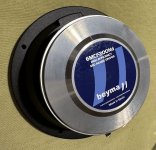
For Sale Beyma 6MCF200Nd. Matched pair

Beyma 6MCF200Nd. Matched pair. New, only opened one for measurement.
PRICE FOR A PAIR:400€
Shipping to europe is 25€, international shipping is 55€, if you want insured shipping please ask for the price. Payment by PayPal, satispay or bank transfer in advance.
my email is franco.cauda@gmail.com

Attachments

  • IMG_8008.jpeg
    IMG_8008.jpeg
    684.5 KB · Views: 158
  • IMG_0462.jpeg
    IMG_0462.jpeg
    721 KB · Views: 181
  • IMG_0461.jpeg
    IMG_0461.jpeg
    662.2 KB · Views: 146
  • IMG_0458.jpeg
    IMG_0458.jpeg
    670.2 KB · Views: 135
  • IMG_0460.jpeg
    IMG_0460.jpeg
    754.6 KB · Views: 143
  • IMG_0459.jpeg
    IMG_0459.jpeg
    659.2 KB · Views: 139

They Dont make films like they used to (90s edition)

So while perusing ebay for a reel to reel recorder (fingers crossed i might have nabbed one), I've been watching Terminator 2 on the telly. I stand firm that the effects hold up against any modern film and cgi peaked here. To my mind the effects in this equal Jason and the Argonauts, especially the skeleton fight, in that no modern remake could touch them for looking so good. Computers and cgi definitely have a place in cinema but I feel they've become lazy.
Discuss?

Compensated transmission line array

Hey folks,

Don't know if it's too weird, but I have this idea of an line array in 3 chambers wich are connected to a transmission line. I try to figure out how to simulate this in hr but I dont get it. The chassis were 9 pcs. dayton pc83-4 in an 3p3s arrangement. The 3 parallel chambers (with 3 chassis in series) should have a port to the tml at 1/4, 1/2 and 3/4. This would normally be a backloaded horn but with an offset of the connected port and on top 3 of them. I found the ME1/2 parameter but I think I need more off a ME2/3/4 instead.

Maybe someone can give me a hint.
Thx!

3emb0t


Edit:
For better understandig, the speaker should look like this:

CTL9_1.png


The acoustic circuit maybe like that:

ACD.png

DATS V3 problem

I have the Dayton Audio DATS V3 speaker tester where the software works on a Windows 10 PC.

I went to install it on another Windows 10 PC and the software starts, but says not responding then closes.

The Windows 10 PC it works on and the one it doesn't work on:

1. Are the same model.
2. Have the same exact hardware configuration. Same model RAM, same processor, same hard drive ETC...
3. Have the same exact software configuration.

By identical I mean that I can swap hard drives between the two and the only thing I might have to do is reactivate Windows.

Also given the PCs are so identical, it should not be possible for me to be having this problem, yet I have it.

Any reason for it not to run on another identical PC?

Hi, hear goes nothing ,

Hi,


My name is Slava, and I currently live in Canada. I have a deep passion for both the world of audio and woodworking/cabinet-making.


I've been following diyAudio on and off for some time now and have greatly enjoyed the discussions.


A bit about my audio journey:
Since 2001, a wave of creativity has driven me to explore the joy of music creation. This passion led me to experiment with various creative aspects—DJing, music production (both live and electronic), and sound engineering. I graduated from film school specializing in sound engineering, built studios, organized events, and rented out numerous sound systems—all while running a business in construction, woodworking, and cabinet-making.


Now, I'm eager to learn even more.


My current venture:
I aim to bring high-fidelity sound to electronic music events by building a custom PA sound system.


Looking forward to sharing knowledge and learning in a supportive environment dedicated to sound reproduction.

Discontinued TI parts (opamps, chipamps)

I still have a small stash of various T.I's discontinued parts. These were purchased directly from my own company many years ago. 100% genuine guaranteed. Price is per piece. Quantity is quite generous.

+ Metal can TO-99 opamps: LME49710HA, LME49720HA, LME49713HA $8
+ OPA827AID SOIC-8 opamp: $8
+ OPA1612 SOIC-8 opamp: $4
+ Chip-amps: LM3875TF, LM3886 $9, LM4780TA $10
Shipping is calculated depending on purchased parts.

I'm looking for trading with the TDA1541A chips and the latest Amanero module.

Thank you.

Attachments

  • 10270284_10203864905971973_4441765098420893339_n.jpg
    10270284_10203864905971973_4441765098420893339_n.jpg
    68.5 KB · Views: 3,328
  • 56985441_398525480703113_991544267442749440_n.jpg
    56985441_398525480703113_991544267442749440_n.jpg
    58.3 KB · Views: 3,345

Asymmetrical Unity Horn

Back in the day, I made a thread about asymmetrical Synergy horns here: https://www.diyaudio.com/community/threads/asymmetrical-synergy-horn.304489/

The idea has always been a bit fascinating to me, because:

1) asymmetrical horns can often have much better WAF. For instance, you can use asymmetrical horns on shallow loudspeakers, so that you don't have to rotate the entire enclosure.

2) I used to be fairly well known in car audio, and in car audio, nearly all of the cars running horns are using asymmetrical horns. I've long believed that it should be possible to improve on these designs, but the vast majority of them are built based on ideas from the 1960s and 1970s. Basically, car audio horns haven't evolved much since 1995 or so.

ProtoDAC build

Kit acquired from @hifiamps (no affiliation otherwise). Original intention was to pair with Rasberry Pi, then I saw @6L6 implemented without. I used:

Mark’s kit so far bog stock
9V trafo
Simple LM317 PS graciously provided by @manniraj (he threw that in when I bought a working MiroAD1862 PCB and PSU1)
Amanero 384 combo input board, an Ali clone
IE socket and fuse holder sourced long ago from ApexJr.
A bit of scrap MDF board

Two issues now resolved- silkscreen on the input card connections didn’t match the ProtoDAC assembly instructions which is apparently a common problem. Searching terms on this forum informed how to move one wire. First fire up yielded a loud crackly sound both channels. @6L6 advised quickly and accurately to add a ground wire between input board and the Proto. Fixed!

So far only played through a scratch built El84 tube amp based on an early Mullard circuit and tiny full range bookshelf speakers, Dell laptop win11 straight in. Sound is very pleasing, quite prominent bass.

Quite something the ProtoDAC, four capacitors five resistors and a daughter card with eight little Philips Dac chips under $100. Next step to listen on the bigger system IronPre + biamped SIT amps.

Not sure if it would benefit from an AmyAlice filter- one is on the way from @ItsAllInMyHead

Thanks folks!

Rohde & Schwarz UPD - HELP! Need docs, files & repair advice

Hi,
I've got a R&S UPD (1030.7500.05) Audio Analyzer in excellent physical shape and apparently complete with one exception: the internal hard drive is missing.

It powers up, and the BIOS boots up. Memory test is ok, but that's as far as it'll go without the hard drive.

I'd like to get this thing up and running again, but am having some trouble locating the info I need. HD type/size, OS files, System files, operating & service manuals, other repair info etc.

Can anyone out there point me in the right direction?

I can find almost NO info on the web regarding the R&S UPD (blog entries, manuals, repair info, tips, tricks etc.)

Given the UPD's capabilities, I'm very curious why there's such an apparent absence of info & interest re this tool, including here at DIYAudio.

Any helpful comments will be very much appreciated.

Cheers!

Revive & restore is the mission.

Hello all. 🙂
I stumbled upon these forums while looking for information on my legacy Rohde & Schwarz UPD, that I would like to keep running as smooth and as long as possible.

My day job is full time hardware development: PCB layout, building prototypes and dealing with RMA / repairs at a small but well equipped company here in Germany. We specialise in DSP based systems including high power rack and plate amps, beam steering applications and audio management over ethernet for large building installations. This is a private account however.

In my free time I play bass guitar, repair guitar amplifiers, pedal effects and the likes.

Looking forward to meeting like-minded folks from all around.

Cheers
Kormoran

Introduction

I’m Glenn from Raleigh, NC. I’m am retired and enjoying it very much. I hold a PhD in management and worked for most of my career in manufacturing and systems management.

Almost 50 years ago I built almost all the components of the Heathkit Pro Series rack audio hi-fi system. I am currently recapping the AA-1800 amp and I will be doing the preamp next. (I also built the GR-2000 TV in 1974.) I have all the components except for the AD-1702 Crossover and still enjoy listening to it.

I am looking forward to talking with other members and learning from them!

For Sale Single Ended Stereo Amplifier - EL84 SE -RH84 Circuit

Hey guys, here we have for sale a single-Ended Tube amplifier I built a few years ago. This is the RH 84 circuit, single ended, one ECC81, and a pair of EL84, with a EZ81 rectifier. The circuit is built on a PCB I bought from a member here, the power transformer is Japanese, from tango, very high-quality with a copper flux band. Power supply capacitors are Rubicon and Chemicon, coupling capacitors are Wima film and foil. The output Transformers are from Elekit. Also, Japanese made.

Neutrik Speakon connectors, and Rca’s. What can I say, it sounds great with sensitive speakers. 4 and 8 ohm secondaries. I will include a spare set of tubes, they are all NOS.

350€ plus shipping, PayPal, friends and family or IBAN transfer.

This will be double boxed encased in hard foam. Shipping is from Vienna, Austria. It would probably be best to keep shipping inside of the EU. Let me know if you have any questions, thanks for looking.

-mac

Attachments

  • 9B34003E-EE30-4442-A30B-5F7A7762D5B3.jpeg
    9B34003E-EE30-4442-A30B-5F7A7762D5B3.jpeg
    959.2 KB · Views: 277
  • 00CE446A-1A8E-4D34-BAD6-370AA0E25326.jpeg
    00CE446A-1A8E-4D34-BAD6-370AA0E25326.jpeg
    1.1 MB · Views: 284
  • CAA1E75F-0646-41AE-808F-AF6F57C7B672.jpeg
    CAA1E75F-0646-41AE-808F-AF6F57C7B672.jpeg
    702.9 KB · Views: 293
  • 61A61B84-3185-439E-8067-D529D7FC3680.jpeg
    61A61B84-3185-439E-8067-D529D7FC3680.jpeg
    1 MB · Views: 276
  • F2E31F05-8889-4A10-AF8E-3ED67D2E6431.jpeg
    F2E31F05-8889-4A10-AF8E-3ED67D2E6431.jpeg
    647.1 KB · Views: 263
  • 95DDB1E6-E790-4160-B8B7-7D97FBD1496B.jpeg
    95DDB1E6-E790-4160-B8B7-7D97FBD1496B.jpeg
    678.8 KB · Views: 275

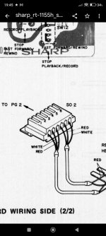
Sharp RT1155 connector help

Dear fellow forum members!
I am looking for a connector for a Sharp deck, the factory number is qcncm102fafzz.
Unfortunately, Google is not my friend, I couldn't find a really good connector. Maybe someone can help me with what kind of connector I can use here? Any JST connector? Thank you for your help!

Attachments

  • Screenshot_2025-03-26-19-45-19-380_com.google.android.apps.nbu.files.jpg
    Screenshot_2025-03-26-19-45-19-380_com.google.android.apps.nbu.files.jpg
    188.8 KB · Views: 24
Projects by fanatics, for fanatics
Get answers and advice for everyone wanting to learn the art of audio.
Join the Community
507,730
Members
7,886,115
Messages

Filter

Forum Statistics

Threads
406,133
Messages
7,886,115
Members
507,730
Latest member
plumb stupid