• Locked
Elsinore Mk 6 Cabinets for Sale

Folks:

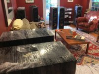
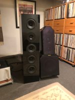
I hosted an Elsinore speaker building project during the Summer of 2018, during which four pairs of Elsinores were completed (see the write-up at Post #2407: https://www.diyaudio.com/community/threads/the-elsinore-project-thread.97043/page-121#post-5690827). This is the Mk 6 version of Joe Rasmussen's Elsinore design. The cabinets were professionally manufactured in a furniture-making factory and finished in beautiful piano black. They sport a few extra features, including a tool-less removable panel to access the crossover space (which is enormous), a removable crossover board, threaded inserts and neodymium magnets embedded in the front panel (to hold a grill in place). What I didn't mention in my write-up was that one extra set of cabinets were produced. That pair of cabinets has been on display since then as evidence of the quality of work the factory can produce. The cabinets are in excellent shape and are now up for sale.

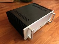
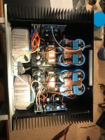
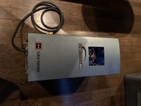
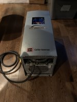
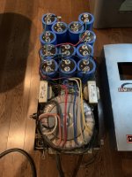
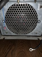
The photos below were taken during the build in my living room and do not include the pair of cabinets for sale now, but the pair for sale is identical to the ones in the photos.

The Elsinore cabinets are not going to be shipped -- creating shipping containers for them is far too much work -- so local pick-up in the Northeast region of Philadelphia, PA will be required. Sorry, but if you want them, you have to come get them. In something big.

Asking price is $1,250 for the pair. Please PM me if interested.

Attachments

  • Three Elsinores wrapped.jpg
    Three Elsinores wrapped.jpg
    431.8 KB · Views: 441
  • Living Room of Elsinores.jpg
    Living Room of Elsinores.jpg
    523.6 KB · Views: 429
  • Andra & Elsinore.jpg
    Andra & Elsinore.jpg
    459.6 KB · Views: 464
  • Like
Reactions: vdi_nenna

DH200 Questions

Just picked up a used DH200 for almost nothing. Have a ST70 that needs new tubes so thought I’d stay in the family and try a classic SS.

After checking fuses, DC offset and bias I hooked her up and except for less mid-bass than my tired ST70, it really sounded pretty good.

Gonna recap, improve the input line to the boards, etc. Most of what I have read here about smart mods and tuneups.

Examining it more closely I’m finding a few anomalies that perhaps someone here can help me with.

The schematic shows a 2.2 ohm resistor on the left input to ground. First, why? And second, why only on the left? Mine is on the right, I’m guessing this was kit built and the assembler mixed up his right and left. Should I move it to the prescribed left input? I’m going to replace the input and speaker terminals with gold plated units so it won’t be much trouble. But I’m confused by this apparent circuit imbalance in a unit often referred to as two identical mono amps.

Lastly, on the bench I can adjust each bias to 275ma but it moves around quite a bit. I have the inputs shorted. It stays in the 275 vicinity but wavers between about 240 and 290, both sides. Will recapping influence that or shall I look for something else in particular? The pots don’t seem noisy and bias changes smoothly with pot adjustments.

Thanks in advance for any advice.

Edit: The schematic shows the 2.2 ohm resistor (R45) on the left input, but the assembly instructions call for it to be installed on the right input.

“Select the 2.2 ohm (red-red-gold) resistor. Cut each lead to 1 1/2" or less. Connect one end to the separate solder lug installed under input socket RS. (S). Connect the other end to the short (ground) lug #2 of socket RS.”

2FFF1C13-FA0E-4C47-A248-875096404C50.jpeg


Jeff

Cambridge cd6 advice

Hi folks
Just wanted to pick your brains I'm an enthusiastic amateur but do have experience is soldering PCBs etc.
I have started tinkering with my Cambridge cd6 that I bought a few years. So this week I decided to recap the servo board. Bought nichicon caps and have slowly removed all the old electrolytic caps and replaced like for like. Plugged it in tonight and now the sled motor is running all the time and won't shut off. Took the board back out and doubled checked everything and it all seems good. I wanted a service manual and hifiengine have one but I'm not a member and can't download it unfortunately.
Does anyone have any ideas what would cause this ? The sled motor was erratic before and made strange noises when you ejected a disc but always worked ok.
Thanks

Q: about PowerDrive

Hi,

I´ve been tempted for a long time to build something quite similar to the TSE but with an adjustable B+ supply and some kind of modular design around the output tube sockets to allow the amp to use a wide range of different power tubes. To get the most out of it I would like to use the PowerDrive circuit but I'm a bit worried about how it behaves during startup. Is the delay/soft start from an IDH tube rectifier (I'm planning on using dual damper diodes) enough to avoid any nasty turn-on pulses into the grids of the output tubes?

Best regards,
Daniel

Grounding Issue on my Instrument

I have an electric violin that was custom built. The Builder is in the UK and I'm in the United States so he cannot look at it. I've only had the violin for a few weeks, but I've noticed lately more noise. It seems like grounding noise. Some things I've found.

I hear the noise when:
Plugging 1/4" directly into an amp that is plugged in to the wall.
Plugging 1/4" directly into an amp that is battery powered
Plugging into my pedal board and then into the amp with both 1/4" and D.I. out

I DON'T hear the noise when:
Using my wireless system (Line 6 G50) to plug the instrument to the pedal board

If I touch the instrument AND something metal like on an pedal or the 1/4" plug the noise stops.
LINK to a video hearing the issue: Login to view embedded media
The maker suggested first try grounding to the metal casing of the volume knob and then if that didn't work, just remove the volume knob and go directly to the output jack. I don't have a ton of experience with this sort of thing so I might find an instrument tech to look at it.

Any ideas?

IMG_6689.JPG
IMG_6690.JPG

Sony STR-DA3000ES protect error 22

I have a sony STR-DA3000ES. It is old - but barely used. Very early on soon after I purchased it, I received a Protect Error 22 on it. It has been in my closet since then. I have scanned the internet - the recommendations all deal with removing the speakers. I have removed all speakers and still get the error code.

I tried to check all output transistors while on the PCB - and they all look the same related to resistance between the pins. Hard to really know if they are good or bad as I have not removed them from the PCB. But the ohms are consistent across the different transistors - so my guess is they are OK (or all bad). One think that I cannot create - put a positive voltage on the gate with ohm meter to turn it on; and then I don't get low resistance when I measure drain to source resistance on any of them. I suspect that may be because they are still mounted in the PCB.

The service manual says Protect 22 : "Two defects a e considered, when current detection of a switching power supply operated by the super fluous speaker, +B power supply shut down or when the power MOS broke and +B line short. Turn off the receiver and check the speaker connection. Then turn on the power again?"

There have been some service bulletins to check on some specific cold solder joints - which I have visually inspected and also checked with ohm meter. They appear OK.

Any ideas on how to narrow the problem?

Need some help

I am looking for someone to design a fairly simple audio circuit for recording musicians. I would need schematics, gerber files and component list. I am of course willing to pay for this service. If you are interested, I can send you the details. my email is rockmixerny@gmail.com

If this is not the right place to ask, I would appreciate it if someone could point me in the right direction.

Thank you in advance!

AD1866 based NOS DAC with 0.2% THD at 1kHz?

Hi everyone,

I'm testing a NOS DAC circuit with the AD1866, the digital signal is fed from an Arduino Due compatible board, the samples are stored in PCM WAVE format 48kHz/16 bit.

The reconstruction filter is the same as suggested in the datasheet but I'm using the LM4562 instead of the NJM2100, I've also included an inverting amplifier, because I've noticed a phase inversion at the output with the suggested circuit.

The DAC and opamps run from a 9V battery based power supply, with a 7805 voltage regulator.

The microcontroller has a separate power supply, being fed from a USB powerbank.

I've recorded the samples from the output of the circuit using the onboard codec of my PC (ALC1220P), THD and SNR was analyzed in MATLAB and I've obtained about -55 dB (0.2%) THD and -63 dB SNR, are those values typical? They seem to differ by much from the values stated by the manufacturer?
The THD results are much worse than those obtained with an architecture based on the DAC8552 and OPA2350 which are under 0.05%, I thought this setup would be an upgrade, maybe I was wrong 😛

Best Regards,
Daniel

Attachments

Loudspeaker protection flawed design?

Hello.
I'm building a p3a amplifier and bought this speaker protection kit, but after assembly it struck me that something is wrong.
It has a perfect 2 sec delay after power up, but if you look at pictures you will see only in and output from relays, so in my opinion the board cannot detect any dc from amp at all, it needs a ground reference.
Am I wrong? I can hook up a wire from it's own psu ground to my amp ground, would it work?, also I'm doing the p3a as dual mono, and I'm afraid this new ground might cause loops, I've been using hifisonix pdf on dual mono grounding.
What is best approach? My two psu grounds have each 10r and a parallel 100nf to chassis ground

Attachments

  • DC-HiFI-Protect-PCB-scaled.jpg
    DC-HiFI-Protect-PCB-scaled.jpg
    802.1 KB · Views: 268
  • s-l1600-1.jpg
    s-l1600-1.jpg
    51.3 KB · Views: 258

Help me identify this potentiometer please.

Hi,
I’ve got a failed potentiometer in the plate amp of my subwoofer. It is a Sunfire True Subwoofer “Signature” by Bob Carver. The volume pot has been iffy and I hit it with Deoxit a few times but it only temporarily fixed. I went to tighten it to the chassis as it is a grounding point and part of it broke (black plastic bits from the back). Now it doesn’t work at all. I can easily solider one in if I can identify a replacement. It uses a “D” flatted connecting rod for the knob. I’m not sure how many ohms it is rated at.

A little tricky to see but the board is labeled “WP-10” under where it is mounted.

Thanks!
Andy

Attachments

  • BA526AF6-B9C8-4B31-A0F0-C0A4D6170AA3.jpeg
    BA526AF6-B9C8-4B31-A0F0-C0A4D6170AA3.jpeg
    286.4 KB · Views: 129

Ultra high current DC blocker

Hi guys
Thanks for everyone who comments here.
I wish to built DC blocker and AC filter for my system.
I have dedicated 35A line that feeds all the system
The system consist of 2 monoblocks of mark Levinson 33H
And of course there is preamp dac and audiophile PC with linear power supply the loudspeakers are very demanding Wilson audio Alexandria XLF.
Mark Levinson recommend to use 30A line for each amp when use in USA 115v 60Hz since I am living in 230v 50Hz area I understand that I need half of the current for each line..
Unfortunately Mark Levinson don't mention power consumption for each amp all I know is that each amp uses 20A main fuse and has idle of 540W ever more each amp uses 3.5KVA transformer.
I have looked at few DC blocker schematics and I saw that most of the design installed on the hot wire and other design installed both hot and natural as well...
Is there any advantages of using both and making it symmetrical ?
I don't know what are the capacitance value that I need ?
How much ripple current I need to feed this 35A line ?
And what voltage rate of capacitors ?
Ever more is there any advantages to use ultra fast and soft recovery diodes in a DC blocker ?
I tried to measure with my fluke 289 and get reading of -150mV DC between natural and ground wires which indicates that the DC current flows from the ground to the natural wire.
I understand that this is one of the problems with the electric company that they connects the natural wire of the transformer to the ground bus bar.

Thank you all
God bless you

Attachments

  • DCB_Power.png
    DCB_Power.png
    52.3 KB · Views: 3,610
  • xfmr-dc-blocking-simpl.gif
    xfmr-dc-blocking-simpl.gif
    5.4 KB · Views: 2,196

Samsung HT-C450N 5.1 Theatre System hissing advice

Hello everyone. Been here a while but first post here. Just looking for some advice on a possible repair.

I have recently been given an Samsung HT-C450N 5.1 Home Theatre System which is perfect for what I want but I have a hissing issue in the satellite speakers. When it is standby the hiss is very quiet as expected, but as soon as it detects a signal and becomes active the hiss becomes significantly louder to the point of irritation, especially at night with lower volume. I have seen online that others have had this issue with both this and other systems, so was hoping I could replace or upgrade something in there, or even add some shielding to at least bring it down a bit.

The hiss is around 7kHz and doesn't change with volume change, balance adjustment, nor input type and I have tried different plug sockets around the house to rule out ground. I would have thought the fact it is not affected by audio volume might point to the possible culprit.

I have swapped out all the main caps for better brands to make sure that wasn't the problem, but it has made little difference. At a bit of a loss as to where to go from here.

I do have a schematic and photos if that might help.

Any help at all would be very much appreciated.

Looking for TubeCad

Good Evening Gentlefolk, I am a newbie in this forum but an old hand at building tube amplifiers, unfortunately very old :-(. Anyway, I read an article about TubeCad and decided to get back in the game and so I set up a virtual machine on my computer, 32bit Windows XP especially to run TubeCad. I am an Electronic Engineer BTW. Anyhoo, When I went to the Glassware site I found that the link to download and pay does not work. Is there any way to obtain and of course pay for this excellent software?

What about a COLD CLASS A Amplifier

Hi Guys
Long time not much to post for me, too much side effects because of that pandemic situation..
Now my Question to all of you is:
What do you think about a CLASS A AMP which runs almost cold if its run below 5 Watts. 25degree Celsius max
This for days or weeks because it will take only 0.35AMP IDLE Current
No need for Fans, can handle Loads as low as 2 Ohms and has a bandwidth 10 - 100Khz +- 1db
Runs on Dual Rails +- 35 Volts is NON Mosfet
Distortion is about 0.03 % under 5 Watts and will claim to 0.4% @ Full load 2 - 8 Ohm doesn't matter
Output max @ 8 Ohms is 15Volts RMS 28 Watts
Sound is good to excellent.
More there is no need for large Toroid Transformers
All my speaker ar 4Ohms and the Amp doesn't heat up.
Will Post Schematic later, so you guys can use your Spice Programs to test.
Now, I have built it, and testing the latest Prototype with the oldest one.
But just to make one thing clear if pulled up to full load it will get hot but again no one is listening all day at 25 or more watts all day.


This is the outcome of the discussion we had once about wasting Power with Class Amps and melting the Ice away from Polar Zones.
Check out the pics, left is Prototype 1 which I made 18months ago, right is Prototype 9 which I made past September, soon number 10 the final one will follow.VCSCAA_00.jpgVCSCAA_01.jpgVCSCAA_02-L.jpgVCSCAA_02-R.jpgVCSCAA_03.jpgVCSCAA_04.jpg

Foil vs electrolytic capacitors for tube amplifier power supplies

Hi

I am not sure if this is the right place to ask this. Feel free to point me to the best forum category. Electrolytic capacitors are mainly used because they are cheaper and smaller and they can hold a much higher capacitance.

My amplifier uses 3x 220uF 450V capacitors for the power supply. I am looking to do some upgrades and I never looked at foil capacitors for those values because I thought they don't exist. However, they do actually exist.

Would there by any benefit in using foil capacitors over electrolytics for power supplies and cathode bypass? Provided there is enough space and they have the necessary capacitance and voltage.

I'd love to hear your opinion

QUAD 2805/2905 dismantling: in pictures (part 2)

In part 1 I exceeded the maximum number of pictures so here is part 2.

IMG_2104.JPG
Undo 8 flat-head screws from the top metal plate and remove it together with the plastic hood underneath it.
IMG_2031.JPG
Each of the 4 (2805) or 6 (2812) panels are connected with wire links and fastened with 4 self-tap screws to metal side bars.
To remove a panel desolder the wire links at the front and rear of the speaker. The HT line is on one side only. Then unscrew the 4 self-tap screws.
Very informative is the old website of One Thing Audio New Page 1
IMG_2080.JPG
The two parts of the panel are kept together with 3 spring clips at each side and three bolts/nuts at the center of the panel. Watch the location of the spring clips.

I think that for most people these pictures and the accompanying text will suffice. The reason I took my ESL apart was that one of my diaphragms has a very very small tear or puncture. Therefore I ordered a Quad repair kit from Eraudio in Australia.

How to widen the listening hotspot

I searched and couldn't find anything related to the optimal listening point of a stereo system and how it can be narrowed or widened to a significant area. Although the subject seems very widely debated, concrete information is few and mixed with a lot of irrelevant information.
What interests me is how the filters (or other details from the speaker) can influence this aspect, how you can use the filters to obtain an optimal audition in a single point or a very wide one.
If there are already these debated things, please direct me to that place.


I mention that I have already read the first topics suggested when I created this topic and I did not find the desired information.

Guitar chip amp design - opinions

Hello
I'm new to this forum and I would like to hear your thoughts on my chip amp design.

The idea is that I can use this as a normal amp and a guitar amp.

In the preamp/buffer section there are two NE5532 opamps, one with no gain and one with gain in parallel. The power section has a TDA7267 opamp.

In normal amp mode the drive mix knob is all the way down, that means no overdrive is mixed in the signal. If overdrive is needed the drive mix knob can blend in some overdrive.

What do you think?

Any help is appreciated!

1673792138901.png

Air core vs steel laminate vs toroidal on a woofer

I have searched this and got a lot of conflicting results. I'm basically curious what your opinions are, and also if anyone here has actually measured the effects of these different inductors on a woofer. In the past, I've always used air core on a midrange and a tweeter, and usually a steal laminate on a woofer (crossed under 500 Hz). But when we had the recent steel laminate shortages, I decided to give C-core toroidal inductors a try... Jantzen 4.7 14 AWG C-Coil Toroidal Inductor

The first build I used this on was a 3 way that used a 10" SB29NRX75-6 woofer, crossed at around 350 Hz (IIRC it was actually a 5.6, not a 4.7). I had originally mocked the crossover up using a steel laminate (same value) from my "crossover voicing stock of crossover parts". But at that time, once I voiced that crossover and it came time to solder everything up, I couldn't find a steel laminate coil (I don't like to use my stock of parts that I use to voice)... so I decided to try that Jantzen toriodal inductor. I was actually pretty shocked, it was an expensive dice roll because I've read the toriodals increase distortion a LOT, but on that woofer the bass seemed tighter, more controlled and simply sounded better than it did using the steel laminate.

Then I did another build, this time it was a TMWW using a pair of 8 ohm Scanspeak Revelator 18W woofers, crossed around 300 Hz. I mocked the xover up again using steel laminate, then purchased a toroidal to replace the steal laminate again. This time the swap didn't change much at all, the toroidals sounded pretty much exactly like the steal laminate on the woofers.

So, based on my experience, it seems like a toroidal is better on a large woofer with a large motor, but on smaller woofers it doesn't really matter. It would be interesting to try an air core on that Scan 18w build, but I'm not willing to spend on a 14awg, 5.6mH air core to try that experiment.

Also, for what it's worth, the actual response of the woofers didn't change much at all in either of those inductor comparisons. But, measuring FR below 400Hz has always been tough to do anyhow so I don't put a whole lot of stock in what my mic tells me down that low. But, as far as SPL and what I could see of the actual bass response, not much changed at all in either of those situations.

So... curious if anyone has actually measured the effects of different coils, and can either substantiate my experience, or tell me I'm delusional :crazy: 😊

MOV Implementation

So I have a Quicksilver Headphone amp (2 x EL84’s and 2 x 12AX7). I was looking around at things and ran across the MOV is implemented in this amp in line with the fuse and power switch. Like this -

320D08BF-24F1-4A35-882F-6DB327768E99.jpeg


Apologies for the crude drawing. But every instance of an MOV I can find is across L and P and not in series. It is usually after the fuse as well, not before.

Can anyone tell me why the designer might have done this? And is it safe to move it to where it should go (across the mains after the fuse)?

I don’t want to remove if it is doing anything worthwhile.

JFET as 1st stage in PLH

Hi
I built a PLH several months ago, am enjoying a lot the sound.
Lately with the heated discussion of using JFET, I am thinking about what benefit it might bring if I subsitute the 1st stage of the PLH, which is an IRF610 by a JFET. I have a few "used" 2SK147 on hand which I want to re-use.
The IRF610 in PLH is biased to over 10mA, seems a bit high for a JFET. If I trim down the bias to a couple of mA, will that be sufficient to drive the MOSFET output stage - reading so much about the capacitance of the MOSFET.
Any advices?

EDEL/engineered SA USB to I2S and SPDIF

I have 8 each of the EDEL/engineered SA USB to I2S and SPDIF boards for sale. These excellent boards were purchased directly from "engineered SA", also known and "ABC PCB" and/or "EDEL". These boards are a previous version of the current USB board, and they are new, old, stock (NOS). Selling them for /$200 US each plus shipping and fees.

Contact me directly via email at fred (at) forsselltech.com

IMG_2175.jpeg

Scan Speak Accuton crossover?

Greeting,
I have Scan Speak Revelator 2904 700009, Accuton C173-6-090 and 3 Accuton C173-11-171.
Can the combo play with 1st or 2nd order crossovers? Or does it have to be 3rd order?
I know that the 1st order crossover is the most phase correct, but the Accuton midrange has pronounced peaks high up, and at the same time the SS Revelator has a significant peak at the resonant frequency.
I was thinking about 2nd order, cuts 240 and 2400 Hz.
What do you think?

China FP10000Q need service manual

Hi,

I need your helping, I have a China clone of a fp10000q works well up that moment ch01 starts clipping and doing strange thing. By looking to oszi and dummy load I saw I miss the positiv halfwave. Hmm, without schematic bad to say where's the problem.
Well without dummy load, I can see a very litte positive halfwave and if give a little more power its a triangle but only withyout load. :hypno2:
By mesering all parts on board I only fine Q22 (MPSA42) blown may be the PWM bord ist blown too or the mysterious A2601 (maybe it ist a optocopler like HCPL2601) is blown too, but I don't no.

May be anyone have a schematic of the Amp-board or the service-maual would be gread, if he sand it to me.

my male is: der.basti(at)yahoo.de

If you have any question or coments feel free to post...

Attachments

  • Amp-Board.JPG
    Amp-Board.JPG
    77.2 KB · Views: 4,771

Crossover upgrade (maybe) Lonpoo LP42

I have been listening to these for a few days. They are pleasant and that cheap 4" woofer actually sounds balanced in the bass, but I can hear what TNT audio shows for the frequency response in elevated mids and high treble. As the woofer has no crossover, I am thinking to add a 1mh inductor to knock down that peak a 1khz a bit, then put a 30-ohm resistor across the tweeter and change the one capacitor from 3.3uf to 4uf to pull the level down a bit. If you have any ideas just from looking at that graph of how you would tweak it, please share.

Sealed subwoofer to bass reflex, what do I gain and what do I lose ?

Ok, I guess I'm a bit mentally inactive and chess just bores me 🙄 , so I'm playing with Win Isd to see what would happen if I converted my two sealed subwoofers (which I built and documented here at Diy Audio ) to bass reflex ...
So I will upload different graphs and ask about the opinion of the experts.
  • Like
Reactions: DblAA

About TA2022 design designers LJM

I think a lot of people in this section have been in touch to TA2022 the IC.

It has real power and the family to use appropriate distortion. And it's very cheap.

But the chip is not easy to design. The group of linear regulator is excellent design scheme of the necessary.

Because of its impedance is not high, about 20 K ohms, so large input capacitance is also useful

I used the 3.3 UF MKP.

The necessary dc protection circuit and cut off the flow of TA2022 itself with protection. Can be a very good protection dc and short circuit.

Attachments

  • IMG_2877.jpg
    IMG_2877.jpg
    341.7 KB · Views: 2,299

How do you store your Resistors and small Capacitors?

All,

This is my question: How do you store your Resistors and small Capacitors?

This is my (and your?) problem: I do own many parts, most small, that need to be stored. Using compartmented small boxes is not ideal (for instance 2 decades of e192 resistors is about a 1000 compartments).

What to do? So I thought I ask my fellow resistor addicts 🙂

Regards,
Frans.

midrange speaker tuning frequency

I have some midrange speakers that I'm trying to design a ported box for. I'm a bit confused about what frequency I should tune the port to.
Another question is: when tuning the box in WinISD, should I aim for a flat graph or a peak? The aim of the speakers is not SQ but rather loudness. but I am unsure if I am better off with a flat response or huge peaks at around 250 Hz (that's what I was able to reach with a non-negative port). I have atteched a picture of the "peak" respons box

Attachments

  • Skärmavbild 2023-02-15 kl. 18.41.16.png
    Skärmavbild 2023-02-15 kl. 18.41.16.png
    9.2 KB · Views: 150

L-C-L power supply calculations in class A SS amplifier

Hi there
It is some while for me writng again something. Personal things led me away from audioo hobby.
But i am back and have much fun again with building stuff.

Lately build an Hiraga amplifier with PCB' s friom Jims audiio, the kubota reg version
I decided to give it a LCL poiwer supply with 80 mH Lundahl chokes LL2772. After first fire up it sounded rather good, but after few tracks and some run in the upper bass is too loud, and bass is boomy, and treble with shshs sounds. Though i calculated the LCL ps with Duncans PS designer it is not sounding right. After removing the chokes out of circuit and there in place 0,33 ohm resistiors, so in fact a Pi filter it sounded much better. Better bass responce and less sibilance

This is my first attempt:
500VA toroid transformer to bridge rectifier with Fets ( diyaudio group buy, from Prasi) > 75000uF> 80mH choke> 31000+31000 uf, each rail/ and each channel apart
so per channel total of 274000 uF of capacity

LL2772 choke is connected in common mode fot extra filtering, the 1+ A bias DC current is then counteracted in the core of the choke

Maybe i should have chosen a bigger coil with less resistance, or add a resistor after the choke, or should choose another capacity distribution (eg first 31000 then choke, then 75000+31000 to amp.)

Matter of fact is the filtering looked good on PS designer, but in AC function with music it is a whole other story. Does anybody have same results with CLC PS ?

Attachments

  • image0.jpeg
    image0.jpeg
    62.2 KB · Views: 87
  • image1.jpeg
    image1.jpeg
    81.3 KB · Views: 87

NJM4558M Upgrade

Hi everyone, my name is Bruno, I'm Brazilian.

I have a pair of Yamaha HS8 monitors, in the signal input circuit, there are 6 NJM4558M op amps, I would like to upgrade to NJM5532M because they are faster, I fear the circuit will wobble.
Will I gain sound quality?
I see that some people put OPA2134 in place of NJM4558...
Could someone more experienced give me an opinion?


A photo of the input circuit board:
20211205_153930[1].jpg


Datasshet NJM4558M:
https://www.njr.com/electronic_device/PDF/NJM4558_E.pdf
Datasheet NJM5532M:
https://br.mouser.com/datasheet/2/294/NJM5532_E-1917664.pdf
See pages 14 and 42 in the service manual.

Attachments

Amp-ectomy: Advice for physically removing solid state amp from active speakers and introducing a distance between the amp and the speakers...

Hi all! I was going to post this in the speaker forums, but now realize this is more of an amp question.

I have a lovely active Genelec 8040b studio monitor... but ... I would love to rip out all the electronics from the speaker and (safely) put them in a separate enclosure. Then the dream would be to use speaker wire to connect the woofer and tweeter (2 x 2-wire) over a modest 20ft cable run without any detrimental effects to sound quality. It would still be the same pairing of amp/speaker, and yes, before you ask, I would close up any resulting holes in the cabinet resulting from the surgery. Since this is a commercial product, I know this would void the warranty, but I don't care haha. I don't have a schematic, but the brochure states it is a class B amp design.

You might be wondering why on earth I'd like to do this? I need to put the speaker in a location where there is already 2 x 2-wire 14awg speaker wire in place, and routing 120V power is technically very difficult.

Before I open up the speaker and test this myself by splicing in 20ft of speaker wire, I would love to know if anyone has ever done such a thing?

Which fullrange driver would work best as a midrange in a 3 way ?

Hi everyone !
I am planning to build a high output three way speaker using fullrange drivers for the midrange. Why not just midrange drivers ? Two things. From personal experience I have noticed that many fullrange drivers have cleaner, less distorted mids than a lot of said-to-be "good" mid drivers at the same or even at a lower price tag. Second thing, I will only be using first order crossovers for this project, so the mid drivers will have to reproduce a non-negligible part of the high frequency content of the signal, hence the need for the wide dispersion characteristics that come with good fullrange drivers.
So, what are your suggestions ? I am not able to listen to enough drivers to find the most appropriate one all by myself, that's why I'm asking.
Thanks in advance

Robert Koda Preamp and LU1014D

Hi, just currious about the famous Koda Preamp gain circuit. If we look at the few pictures available, seems to me it use the LU1014D, with some large Mosfet, with possibly a CRC supply filter, and JFET input buffer.

Parts choice seems pretty usual: vishay, PRP, and MFR25 film resistors, Elna for audio, Muse and Nichicon Rubicon VZ electro caps.
Even the power supply rectifiers seems to be on the board.

Anyone knows the used topology? Just curious…

SB

Attachments

  • 6B64682C-4898-46C6-8607-946DDFD52C3C.jpeg
    6B64682C-4898-46C6-8607-946DDFD52C3C.jpeg
    11.9 KB · Views: 289
  • 066A37F6-9ADD-434F-A9B8-275FFDC31019.png
    066A37F6-9ADD-434F-A9B8-275FFDC31019.png
    78.3 KB · Views: 344

Studer A730 CD player spins backwards

Hi all,

Can anyone suggest a track, as I am running out of ideas searching where is the cause of my old Studer A730's todays issue : as soon as it's powered on, even if lid is open, motor starts spinning backwards at full speed and machine doesn't respond to any order. Swing arm goes full travel outward to disc end, lens tries focusing and laser beam is visible.

Machine fully overhauled 3 years ago (all electrolytics, fresh battery) and it has been playing faultless since. I hadn't used it at all during last 3 or 4 months, but until then it has been working flawlessly.

Some years ago it has been retrofitted by Studer with a CDM-4/16 drive (Neues Laufwerk für A730 Umbaukit MkII 1.630.027.81)

I checked all power supply voltages (+5/-5V, 12V, -15V) and they're all within specifications.

For the time being I'm lost...

Tube 6DJ8/ECC88 Half-Diamond/ Anode-Follower Hybrid preamp or buffer

Hi!

I am looking for tube buffer or preamp design using with 6DJ8 or maybe someone can suggest better tube for this project. Looking for very good soundstage, very low THD like 0,01% and less. Something that touches mind body and soul. I like to use one tube per channel or one tube for stereo buffer like Aum Acoustics Single Triode Tube Buffer. Can anybody point me to the right schematic to do something like this Aum tube buffer?

I am planning to use high PSRR power supply like 21 century Maida regulator for high voltage and for heaters also PSU with 100db PSRR. Balanced in and output option using some buffer or any better ideas how to solve that issue to use both balanced and unbalanced tube amp?

I picked up these sample schematics looking for very low THD, PSRR and good attenuated harmonics. It would be good if the gain for this buffer or preamp rather low. Planning to use sometimes up to 2Vrms input and output balanced 4Vrms option.

Please comment about these schematics and your experiences with this kind of tube amps like:
1675717560857.png


or
1675717623020.png


or
1675717655444.png

https://www.tubecad.com/2019/05/blog0465.htm
or
1675718174860.png


https://www.tubecad.com/2022/07/blog0561.htm

Any help and your experiences with a tube amps would be highly appreciated. 🙂

  • Locked
FC - 100 parts

Good day, gentlemen
1676465225025 - Kopie.jpg
1676465178480.jpg
1676465178475.jpg
1676465178470.jpg

due to lack of time to realize this project i offer it for sale.
the main transistors have not even been opened by mouser and the others are new from my findings. I also have instructions with me.
I don't want to enrich myself but simply give it away at a fair price.alone the transistors are more expensive than this offer.
want for everything
€160 plus shipping

ChatGPT helpful advice on my CD Player

So, I've got a 506 CD player and I'm wondering what I should do with it as I don't play CDs any more. Thought I'd ask chatGPT and this is what got. Which I thought was fascinating and somewhat scary at the same time. Can't help but be impressed, particularly with the bit about S/N starting 2 & upgrades...

what DAC chip is in a Meridian 506 series CD player?

The Meridian 506 series CD player uses a proprietary DAC (digital-to-analog converter) module developed by Meridian, rather than an off-the-shelf DAC chip from a third-party manufacturer. The specific model of the DAC module may vary depending on the exact version and year of production of the 506 CD player. Meridian has not publicly disclosed the specific DAC module used in the 506 CD player. However, Meridian has a reputation for developing high-quality proprietary digital audio technologies, and the 506 CD player is widely regarded as a high-end audiophile-grade CD player.

how easy it it to upgrade a 506 from 16 bit to 20 bit?

It is not possible to upgrade the Meridian 506 CD player from 16-bit to 20-bit. The 506 CD player was originally designed and manufactured with a 16-bit DAC (digital-to-analog converter), which means that it is only capable of processing 16-bit audio signals. While it is theoretically possible to replace the 16-bit DAC with a 20-bit DAC, doing so would require extensive modifications to the circuitry and firmware of the CD player, which is beyond the scope of a typical user upgrade.
Furthermore, even if it were possible to upgrade the 506 CD player with a 20-bit DAC, the improvement in audio quality would likely be minimal, as the difference between 16-bit and 20-bit audio is subtle and may not be noticeable in most listening environments. It is also worth noting that the audio quality of the 506 CD player is determined not just by the bit depth of the DAC, but also by factors such as the quality of the transport mechanism, the power supply, and the analog output stage. Upgrading any of these components may result in a more noticeable improvement in audio quality than upgrading the DAC alone.


I'd read that 506 player with serial number starting 2 were upgradeable to 20 bit?

You are correct, some of the later Meridian 506 CD players with a serial number beginning with "2" were offered with an upgrade path to 20-bit resolution. This upgrade was performed by Meridian and involved replacing the original 16-bit DAC module with a 20-bit DAC module, as well as making other modifications to the player's circuitry and power supply.
However, it's worth noting that this upgrade was only available for a limited period of time and may no longer be available. Also, the upgrade may only be available for specific models or versions of the 506 CD player, so it's important to check with Meridian to confirm if your specific player is eligible for the upgrade.
If you do decide to pursue the upgrade, it's important to have it done by a qualified technician who is familiar with the Meridian 506 CD player and has experience performing this type of modification. Additionally, it's important to carefully consider the cost of the upgrade versus the potential improvement in audio quality, as the benefits of upgrading from 16-bit to 20-bit resolution may be relatively modest and may not justify the expense.

what sort of price does the 506 sell for in the UK?

The price of a Meridian 506 CD player in the UK can vary depending on several factors, including the specific model and version of the player, its condition, and whether any upgrades have been performed. As the 506 CD player is a discontinued model, it is sold primarily on the second-hand market.

Based on current listings on various UK-based online marketplaces, the price of a used Meridian 506 CD player typically ranges from £500 to £1,500, depending on the factors mentioned above. Prices can also vary depending on the seller, so it's always a good idea to shop around and compare prices before making a purchase.

It's worth noting that the availability of the Meridian 506 CD player may be limited in the UK, as it is no longer in production and may be difficult to find in certain areas. Additionally, as with any second-hand purchase, it's important to carefully evaluate the condition of the player and its components before making a purchase to ensure that it is in good working order.

Marshall Plexi problem

so i'm currently looking at a Marshall re-issue plexi from 1987 that has been hacked by someone attempting to make mods and remove the effects loop, needless to say i've had to rewire much of the pre-amp and replace a tube socket (someone cut a plate pin from the V1 tube socket) and replace missing components in order to get back to original but encountered something that i can't account for...now with the pre-amp volume controls fully counterclockwise there's still signal....i've lost my mind investigating grounds to no avail so am left wondering if this is normal??

What size Allen key for Fender Jazzmaster to adjust bridge segments?

A friend has asked me to adjust the intonation of his Jazzmaster. Turns out it has screws with heads that need an Allen key. The required size is about 2mm or maybe 1/16 inch. Does anyone know the exact size? I don't really want to drag the guitar around the aisles of the local hardware store to see which size fits. Picture of setup below.

https://static1.s123-cdn-static-a.com/uploads/6485140/2000_62bb4e2baf6e2.jpg

Looking for a Non Functioning Vintage Amp for a Project (or a suitable enclosure)

I am looking for a vintage amp or a vintage looking chassis for a project lamp for my listening room. Must be not worth for restoration as an amp as I will gut it.

Yes I said that, I want to make a "lamplifier". I have a couple of Manley Snappers that have a cool glow but need a bit more illumination for certain listening times.

I'm hopping to build a lamp with some edison style bulbs (dimmable, wifi controlled) to illuminate the front of the room.

I'm thinking of using the knobs for switch and dimmer (volume).

Have tried eBay but have not found anything I like.

Old member can't send private message.

Ok

I admit i haven't been the most active member since 2016 😛

I'm still here... And i would like to send a private message and i am being treated as a "NEW" member


1676439469804.png


So... Do I have to make some random post's (how many?) to show that i am a human being,
or some ADMIN can fix this? Or is there another solution?

I would really like to send a private message to another member.

Cheers
  • Like
Reactions: Jason

Can I reduce sub cabinet size by increasing passive radiators size?

I saw that the correct size for PR is twice the sub size, but as I want a minimum box size, I wonder if I can increase the total surface of the PRs, in order to reduce the box size, bellow the recommended size for the speaker characteristics.
I plan to build a sub with a Dayton Epique E180HE-44 with it’s associated PR HE180HE-PR.
could I put 4 PR (One on each side of the box)?

For Sale Nelson Pass Tribute - Class A Space Heater - Free to a Nelson Fan - Local Pick Up Only

Ok folks, in honor of the man himself, Mr. Nelson Pass, I am offering this space heater for free - all you have to do is be a bona fide fan of The One and Only, and come pick it up locally in Vancouver as this thing weighs around 100lbs.

So what do we have here, well this is a decommissioned & repurposed VFD with a very high quality tubular fan added to push air through some truly enormous heat sinks. I won't hazard a guess at exactly how much power you could push through this and still keep the gain stages at comfortable temperatures but I bet it is a lot. The top layer of this beast is the CLC power supply full of big caps, inductors, bridge rectifier diodes (some fancy soft recovery ones if I recall correctly) and a monster toroidal transformer. At a guess there is probably $1,000 or more in parts here before we figure out the heatsinks.

This would be a great winter space heater for one of Nelson's Class A designs - Nelson you brought me a lot of joy over the years - this is my way of saying thank you.

Tell us why you deserve this and it's all yours.

Cheers

Attachments

  • IMG_3837.JPG
    IMG_3837.JPG
    401.2 KB · Views: 346
  • IMG_3834.JPG
    IMG_3834.JPG
    402.7 KB · Views: 342
  • IMG_3836.JPG
    IMG_3836.JPG
    391.9 KB · Views: 349
  • IMG_3741.JPG
    IMG_3741.JPG
    496.8 KB · Views: 355
  • IMG_3747.JPG
    IMG_3747.JPG
    744.5 KB · Views: 343
  • IMG_3832.JPG
    IMG_3832.JPG
    709.1 KB · Views: 337
  • IMG_3743.JPG
    IMG_3743.JPG
    635.9 KB · Views: 327
  • IMG_3833.JPG
    IMG_3833.JPG
    369.3 KB · Views: 350

"Speakers Don't Sound Real, Lets Build One That Does" (Dave Rat)

(Didnt know where to put this - ended up in fullrange as those are the drivers used)

Link to an interesting youtube video by Dave Rat on stereo/hifi reproduction and why he thinks it still falls short: Speakers Don't Sound Real, Lets Build One That Does
The demo uses a, multi-mic'd, guitar played back through four fullrange speakers; all pointing in different directions.
(His, practical, methods might make some of you shudder, but, you cant deny, he has an infectious curiosity for all things sound related)


I think he has a good point about how things are/can be recorded vs how we, try to, listen and recreate the original enviroment... What do you think?

Floor spikes again...

The floorstanding T-M-M speakers I'm building are 8-1/2" wide by 10-3/4" deep by 44" high, and sit on a carpeted concrete floor in the lower level of our home. I was planning to add four spikes to the bottom of each somewhat top-heavy speaker to penetrate the carpet and increase its stability.
I see that many people place little metal cups under speaker spikes, presumably to protect the floor. Wouldn't these just eliminate the value of the spikes?
Also, I've read that using spikes increases speaker cabinet vibration. I'd assume this is a bad thing in most circumstances, but does it all come down to the room and personal taste?

Pass PLH Build Question

I have started building the Pass PLH project but stumbled on Papa's suggestion to make P2 a 2-5W trimmer resistor, which part is suggested for this. I can't find trimmer resistors this high? Also, what about R6 wattage? is it OK as a 1/2w or 1W resistor?

Also, can I use 27V power supplies like in the JLH version? Is there any mods I have to do to use lower voltage supply?

Partial filling of cross section of a transmission line

I noticed that many (mostly vintage commercial) TL speakers aren't stuffed with a damping material but lined instead with something like acoustic foam or polyester mat. Usually this lining occupies about one half of the cross section, may be a bit more. So my question is how does it change the development process? I may want to try a polyester mat (the stuff used for like winter jackets) as it just easier to work with. Can I just average the density over the cross section? I rely on Hornresp if it matters.

Jordan Eikona Translam Ellipsoid

About 18 months ago I purchased a pair of Jordan eikona 2 drivers. Just before I was about to start making some sawdust I had to move house which put the whole speaker project on hold. Fortunately for me my new house has something that I've never had before, a workshop. My original speaker plans had been for a pretty ordinary box as this was as much as I could manage with my old set up. With the space my new workshop offered I could get really creative. A complete redesign was required. The house move presented many other projects that needed to come before the speakers such as new equipment racks and wiring mains electricity to the workshop.
I have finally got to the point where I can start making the cabinets. I have the design sorted, and have made the jigs and tools that will be required and have received most of the materials.
I'm planning on splitting the thread into two parts. First off I'll describe my design decisions. Then I'll document the actual build.

My design goals are to achieve the best possible sound quality (of course) and to make something that visually wows, not by being over the top and garish but by being beautiful. I don't have the largest listening room so they are going to be stand mounted and reasonably compact.
I think my design should achieve these goals.

First installment to follow soon.

Niffy

Mission Cyrus Tuner recapping

I love tuners. I've got several of them, including receivers. This time I decided to recap my old Mission Tuner. It's been built in 1985, April 20th to be precise (thanks to Mission folks who identified this on the PCB). Why did I do that? Because it's 36 years old, and the blue Philips caps are not known to last forever. Also, I noticed that it's going wrong sometimes, not able to keep frequency or signal, whether cold or warm (alternatively). So I thought that I could see what's around and detect potential problems here at first.

The PCB is quite simple to get out, I won't insist on this. Always take pictures before, and use some small paper sticks to remember where the wires go.

Taking the electrolytic caps apart and measuring them (twice on 2 different devices), ALL blue Philips were out of specs. Really out (like 2µF instead of 100, or ESR > 40ohm...). The only one that was good was a small yellow Nichicon (probably an old repair).

Good news, as it is a quite simple job to do. Hoping that it will be enough.

Having taken out all of them, I'm now able to make a comprehensive list (BOM) that I post as a picture down this page. in case it's useful for someone without unsolder them all before ordering. There could be some small differences if the model is different, of course, but I guess it should be near the values on this list. Of course, would anyone need the xls file, just ask.

I post a picture of the PCB once all electrolytic caps taken out, so one can see where they take place and which values they are. I wrote values on the picture at the exact place where you'll find the caps.

I'm waiting for 680µ/16V I had forgot to order on my first try 😕 to finish the work. While I'm waiting for the parts, I've decided to repair the small issues (broken plastic lugs as usual on the Mission apparels, cleaning and solder reflow where necessary, maybe a metal cover on top of the HF tuner section if I find some adequate piece of steel in my small recycle mess...).

I'll post pictures of the final condition if after all that, the tuner is OK.

Thanks for reading, I'm happy if it can help someone.

Attachments

15'' hi-efficiency woofer that reach F3 40Hz in 150L

hi everyone

I'm looking for a very good woofer that can go low in a enclosure of 150liter of even smaller.

I was planning on using my eminence omega pro 15 but they dont go low enough in 150l so im looking for alternatives:
I require about 98db eff driver to mate with my pr170mo and hivi rt2h ribbons
so far, the best via simulation is the:
Beyma 15b100

I wonder if im missing many other otions

any help would be great
thanks

Sonic Frontiers SFCD1 Issue

I have come to this community for some sound advice.
I have a Sonic Frontiers CD1 with the left channel creating a wooshing noise heard mostly through the tweeter because of the higher frequency. The noise only happens when music is playing and is volume dependent, gets louder as the volume is increased/decreased. The music is playing flawlessly, with overlaying sound rushing or whooshing, only way I can describe it. I thought it could be dirty contacts on the relay of the left output stage and have replaced that relay with a new one. Sadly no improvement. If it is the DAC I am going to be in trouble since they are no longer in production. Any ideas people? It would be much appreciated.
Projects by fanatics, for fanatics
Get answers and advice for everyone wanting to learn the art of audio.
Join the Community
507,624
Members
7,880,739
Messages

Filter

Forum Statistics

Threads
405,895
Messages
7,880,739
Members
507,624
Latest member
Neilonpoint