Hi guys
Thanks for everyone who comments here.
I wish to built DC blocker and AC filter for my system.
I have dedicated 35A line that feeds all the system
The system consist of 2 monoblocks of mark Levinson 33H
And of course there is preamp dac and audiophile PC with linear power supply the loudspeakers are very demanding Wilson audio Alexandria XLF.
Mark Levinson recommend to use 30A line for each amp when use in USA 115v 60Hz since I am living in 230v 50Hz area I understand that I need half of the current for each line..
Unfortunately Mark Levinson don't mention power consumption for each amp all I know is that each amp uses 20A main fuse and has idle of 540W ever more each amp uses 3.5KVA transformer.
I have looked at few DC blocker schematics and I saw that most of the design installed on the hot wire and other design installed both hot and natural as well...
Is there any advantages of using both and making it symmetrical ?
I don't know what are the capacitance value that I need ?
How much ripple current I need to feed this 35A line ?
And what voltage rate of capacitors ?
Ever more is there any advantages to use ultra fast and soft recovery diodes in a DC blocker ?
I tried to measure with my fluke 289 and get reading of -150mV DC between natural and ground wires which indicates that the DC current flows from the ground to the natural wire.
I understand that this is one of the problems with the electric company that they connects the natural wire of the transformer to the ground bus bar.
Thank you all
God bless you
Attachments

Thank you Molly
I have red this half of it I didn't understand
Ever more questions like advantages of using at the natural wire as well I didn't saw...
I have red this half of it I didn't understand
Ever more questions like advantages of using at the natural wire as well I didn't saw...
Just buy a sjostrom DC blocker, the bigger model from Per Anders. Works perfectly on big amps.

I know that is always easy to plug and play ��
But still I wish to understand why most of the designs do not use the natural wire as well ??
But still I wish to understand why most of the designs do not use the natural wire as well ??
In a TNS type mains system, any switch or fuse component must be in the active line - there should be no switched part in the neutral. If something goes wrong with the DC blocker circuitry, it is 'safer' for it to be in the active lead, not the neutral lead.
There are no advantages, and only a disadvantage (the safety aspect above) in making it a symmetrical arrangement with active/neutral lines.
Rod's article identifies the general sizing of the ripple current rating of the 'capacitor' - it is the max anticipated current of your load equipment. If each equipment has a 3.5kVA transformer, then size the ripple current requirement for that.
There is no effective benefit from using anything but a robust bridge. In your situation you are using load with considerably more VA rating than most others would consider, or provide design details for, so I would suggest you identify a more robust bridge than a 35A rated device.
The voltage rating of the capacitors don't change from what Rod identifies.
The measurement of voltage between neutral and protective earth is not an indicator of DC current passing through the primary winding of your equipment. To get a good indication of whether DC current is being passed and is upsetting your equipment transformer, you can use a current sensor (such as a LEM type device) to observe the waveform to see if it is symmetric or has a strong assymetry and saturation related peak to the waveform. To get an idea of whether there is some DC component to the AC voltage between active and neutral then Rod provides a method of measurement.
Last edited:
Thank you Molly
I have red this half of it I didn't understand
Ever more questions like advantages of using at the natural wire as well I didn't saw...
You mean the neutral wire...
The transformer primary is a simple series circuit, mains in at one end and out at the other. You can place the DC blocking elements anywhere within that path.
Thank you guys
Trobbins I have understand that one of the tn-s problem is that noise enters through the natural wire...
Or is it common mode noise ?
Ever more can DC enters through the ground ?
Trobbins I have understand that one of the tn-s problem is that noise enters through the natural wire...
Or is it common mode noise ?
Ever more can DC enters through the ground ?
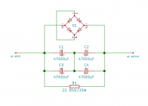
70HF-HFR40 refers to each individual diode shown in the schematic. The four diodes could be shown in a bridge formation, along with extra connections to achieve the same result - they just chose to draw it that way.But if I understand correctly it's not a diode bridge ???
Do do you think it's DC blocker ?
As you can see mark installed it at the hot wire and the natural as well..
As you can see mark installed it at the hot wire and the natural as well..
As per the link provided by Mooly, Mains DC and Transformers , they are diode bridges with the ac inputs being the line/neutral inputs/outputs but the +/- bridge outputs are shorted together. I suppose it is not immediately obvious because the schematic you have provided does not show a standard rectifier connection, diodes swapped. Swap the bottom pair with +/- still shorted. Operationally the same circuit. Remove the short to access +/- and it looks like a standard bridge connection.
Do do you think it's DC blocker ?
As you can see mark installed it at the hot wire and the natural as well..
Yes it is. Adding an additional blocker won't improve anything. And please stop calling the neutral natural.
montana, working on AC mains side parts and circuitry is dangerous and should only be done by a competent person. That is especially the situation when any work or alteration involves an element of design or assessment, as those aspects often go beyond the skillset of an electrician. Some forums don't allow threads that go to AC mains side alterations or projects - with good reason.
As an alternative solution to equipment that is suffering from DC on mains AC supply type issues, a dedicated isolation transformer could be interposed to supply all your audio equipment as that won't pass DC.
As an alternative solution to equipment that is suffering from DC on mains AC supply type issues, a dedicated isolation transformer could be interposed to supply all your audio equipment as that won't pass DC.
Ok I will. One thing that concerns me regarding the main power supply diode bridges. Since mark Levinson uses 70A rated for each diode they are standard recovery and of course not soft recovery. He uses 1.5uf in parallel to avoid noise. If I will decide to replace them by SIC Schottky diodes or GaAs schottky when they will produce in 600v.
In that case should I need to remove the 1.5uf caps in parallel ?
In that case should I need to remove the 1.5uf caps in parallel ?
Attachments
PCB for DC Trap Blocker Filter for toroids – v.3 | ATL Audio Ltd.
DC Blocker Trap Filter – Populated PCB – v.3 | ATL Audio Ltd.
and with case.
DC Blocker Trap Filter – Assembled in Case – v.3 | ATL Audio Ltd.
DC Blocker + RF / EMI too, the same three options.
Combined module DC Blocker (trap, filter) & EMI/RFI/Common Mode Filter – assembled and tested PCB | ATL Audio Ltd.
DC Blocker Trap Filter – Populated PCB – v.3 | ATL Audio Ltd.
and with case.
DC Blocker Trap Filter – Assembled in Case – v.3 | ATL Audio Ltd.
An externally hosted image should be here but it was not working when we last tested it.
DC Blocker + RF / EMI too, the same three options.
Combined module DC Blocker (trap, filter) & EMI/RFI/Common Mode Filter – assembled and tested PCB | ATL Audio Ltd.
An externally hosted image should be here but it was not working when we last tested it.
An externally hosted image should be here but it was not working when we last tested it.
Last edited:
Maty, do you realise that ebay item has no AC mains current rating, and the referenced amplifier appears to have a 3A mains fuse for 240VAC and a 750W max consumption?
In contrast, the OP's audio system may draw well in excess of what that eBay item can support.
In contrast, the OP's audio system may draw well in excess of what that eBay item can support.
The best is to ask to Aleksandar (ATL Audio) but 3A is not a problem. He cans build it with the specifications required by the customer, like me with mine DC Blockers.
dc blocker maty - Google Search and go to Images
dc blocker maty - Google Search and go to Images
Last edited:
Just buy a sjostrom DC blocker, the bigger model from Per Anders. Works perfectly on big amps.
The improvement on sound in system is Huge. Just mount it in series with the power bar for the hole system. Best upgrade for a very long time. Dynamics gets much better.
Yes these amps got DC blockers, no need to add an external one... In fact these amps got probably all the bell and whistles you can dream of, the real thing, very good over engineering audiophile beasts...
- Home
- Amplifiers
- Power Supplies
- Ultra high current DC blocker