RS225 vs L22RNX/P

Hi all

Here in EU the price are pretty similar. But Seas seems to show their measurement for this driver, in only 21 liters(written in small, under the FR ):
http://www.seas.no/images/stories/prestige/pdfdatasheet/h1252_l22rnx_p_datasheet.pdf

Dayton recommend around 12,5 liters:
https://www.daytonaudio.com/product/104/rs225-8-8-reference-woofer-8-ohm

SB23NRX recommend somewhere between 38-75 liters:
https://www.soundimports.eu/en/sb-acoustics-sb23nrxs45-8.html

I Have 3 way mains and 4 subwoofers and have 12 channels of amplification and DSP for each. So I need midwoofers to blend nicely with subwoofers - around 50 - 500hz.

I would like to build something sleek looking like a Jamo 707i or Dali evidence 870. Everything above around 500hz is handled by an SB MW13TX and SB26ADC in 5" Augerpro waveguide.
Subwoofers are four individual boxes - 2 x 12" SS Discovery( 90 liters ) and 2 x 15" Dayton RS390HF ( 125 liters ) - all closed.

So... are different brands recommendations a bit off? Did they forget to be specific about the Q of a given volume? Because I could make the woofer part around 60 liters... just making the design deeper. But it would be nice to know how much artistic freedome I have - given the moderne possibilites from DSP and amplification. Of course keeping in mind, the goal of excelent sound quality.

I should be able to figure this out myself.... but I'm a little baffled - no pun intended 😊

DiyinHK 8 channel Dac

I'm very tempted by this dac for a multi-channel setup. Has anyone had experience with it? I'm particularly interested in having access to each channels volume control. I'm assuming that I can do this via an arduino but I can't find any info on how to set this up. Any ideas?

Alternatively, the Topping DM7 looks like a good idea = who can help me hack it so I can have access to the individual volume channels? There is a reward waiting....


https://www.diyinhk.com/shop/audio-.../33-dac-xmos_and_dac_pcb/141-fifo_option-null

Quikea diy sound diffusers

Hello guys,

I wanted to share my experience on building few sound diffusors 2 years ago.
We know they can be very expensive from a shop if you want to cover enough, but can also be very ugly if you diy while not so versed in woodworking, like me.
Well I like wood working but it's just very hard to get the clean finish I want, too impatient and I just have basic tools.

In my previous room I had a mix of Decware, ATSacoustics and Giks with great effect.
Money was not a problem at that time, but now the room is twice the size and I really needed a different solution.
Plus I would then be able to define the right frequencies and go a little lower with more depth.

So I wanted to find a good compromise, cheap, fast, easy, while good looking enough.
Re-using an existing and clean looking box was a solution.
But it's not only the box, I also needed to build the wells and fins with what I could find around at a good price (right when wood price started to fly up).
Meaning lumbers and mdf panels with the right dimensions with minimal cuts for the boxes I could find.
Plus I wanted the process to be simple and repeatable, tolerant to human errors, so they would all look and behave alike.
So the lumber cuts/wells dimensions needed to be integer, not too hard to repeat.

Started by looking around all shops for simple box, wood preferably but all kind really.
Then based on theirs size I would calculate the right dimensions for the fins and the wells.
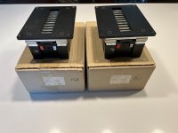
Took a lot of back and forth but I ended with an ikea besta, 60x64x20cm, that exists in black or tan.

besta-structure-effet-chene-blanchi__0316134_pe513535_s5.jpg - copie.jpg


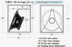
It allowed a double symmetric QRD n7 with 38mm wells and 6mm fins with an F low around 350Hz and an F high around 4700Hz, perfect for my OB midranges.
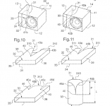
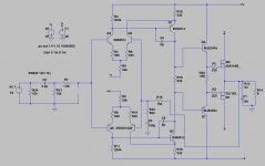
See calc:
Capture d’écran 2023-02-16 à 11.05.07.png

Here only half:
Capture d’écran 2023-02-16 à 10.49.54.png

dif02_uk.gif


Wells from left to right, in mm: 20 box left wall, 12x6 fins + 13x38 wells, 20 box right wall
Depths: 0 - 50 - 200 - 100 - 100 - 200 - 50 - 0 - 50 - 200 - 100 - 100 - 200 - 50 - 0
The 0.8mm added in width were need to include the fins thickness in the wells width calculation.
You will later notice it's not an exact symmetry since side walls/half wells are 20mm and the central one is 50mm with its 2 side fins.
I believe the effect is minimal, and it was just too hard to build without 2 fins on the central one to hold it.
Also once the boxes are stacked there is a little gap between them, so it kind of repeat the width of the central one. Details details...

Price-wise, it was quite some time ago so I don't have all details, but I remember calculating something like 40 euros per diffuser.
I just checked the besta price, now at 35 euros, they were for sure cheaper at that time, I think I remember 20 euros but maybe I’m wrong.
Plus I got more than half in the demo/used corner ready to go.
For the lumbers I had to visit few shops as the real dimensions can differ of their listed spec.
I started with 8 boxes but decided for more after and was lucky enough to find lots with the exact same dimensions as the lumbers I see now are not consistent.
Mdf in 6mm is cheap, especially with the big panel 250/120cm, I didn't try thinner as it was too flimsy.
Big panels are just a pain to cut without proper table but it saved quite a bit I remember.


Process (no pics sorry I didn't think of that):

1 - build the box, without the back panel, doesn't need added glue it's sturdy enough

2 - cut all lumbers to 58cm length, the internal height of the box. Trial and error but 1mm variation is ok. remove the non straight enough ones.

3 - cut mdf into 20x58cm, box height + a little more depth for some to allow glueing the deepest wells at 20cm.
I could have saved even more $ by optimising the cuts here but it was just easier to cut them all at the same dimensions, roughly. Their height is important though of course, needs a 1mm precision, and a clean "front" cut, the back one can be ugly.

4 - dry mount, here I'll try to describe what I did:
Put the box flat on the table, final front facing up.
Then use 13 spare wells (or cut leftover) with the 12 final fins to fit everything first, the wells deep to touch the table, it can be be tight so be careful to not bend the fins, use another lumber to push them.
Then I'd stack more spare wells to define the final depth (I used 25x38, so stacking them would give me the right calculated depth 5/10/20 etc, another place to save money here with thinner lumbers but it was easier)
So row 1: 5 stacked wells + 1 final well gives a final front depth of 5cm, 20-(6x2.5).
Row 2: just 2/3 spare wells to keep the fins in place for now.
Row 3&4: 3 spare wells + 1 final well gives a final front depth of 10cm, 20-(4x2.5).
Etc for other rows.

5- glueing
Once all the stacks are done, I will glue the final wells on top, pushing them to fit tight.
I wasn't sure the glue would be ok on the box surface that is plastic covered, but it was fine it worked.
Once all final wells are glued, put the box carefully on its base, and glue the 2 wells at the back for the deepest depths (row 2&5).
Placed by hand is enough, just make sure you get the 20cm depth in front.
keep drying 1 day.

6 - spare removal
Once all dried you can remove all spares and use them for the next diffuser.
I used to do 1 or 2 a day and it took less than 30min for the last ones.
Only one was not sturdy enough at the end, due to too short fins, added glue from behind fixed it.
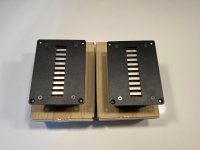
Results:

IMG_0853.JPG
IMG_0851.JPG
IMG_0852.JPG


Boxes are solid while still light, can be stacked 3 or more, and moved around safely.
I've just built a base structure as my ground is not flat.
Once all fins are glued they stay in place, but don't push too hard on them.
With the leds the effect is I think pretty cool, lovely at night.

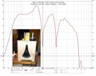
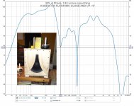
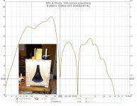
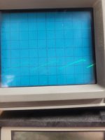
I need to dig-in to find some "before" measurements, I have so many I'm not sure I’ll find the right ones.
Not even sure it will be visible there, but I do prefer with 9 per side for sure, while 4 per side already had an effect.
The room is rectangular, and I use it in its width, so it helped a lot to get back some depth in the soundstage, virtually increased it.
Now I have to work on bass traps...

UNIVERSAL SPEAKER PROTECTION 2PCB+2RELAYS

For sale is universal speaker protection that get supply from amplifier PSU, and 1PCB with 1RELAY is enought for STEREO speaker protection.

This protection have the following protections module:

  • turn ON delay
  • AC Power Off (turn speaker off after amplifier power is turned off, so there is no PUFFF in speakers when you turn of amplifier)
  • DC Voltage detection on speaker (to protect expensive speakers)
  • short circuit protection for output amplifier BJT or MOSFETS stage
  • uses high quality relay to maximize sound quality
  • it uses professionally made routed PCB that accept RN60D resistors and custom made inductor
  • it takes supply from different PSU voltage that feeds audio amplifier so few resistors needs to be calculated to satisfty custom amplifier psu working voltage

For sale is last 2 sets (1 set is 1PCB & 1RELAY), and interested please write PM with your country so that i can calculate shipping costs...payment is via paypal.

speaker-protection-schematic.png

1.jpg

2.jpg

3.jpg

4.jpg

speaker-protection-model1.png

Thanks for your time.

Rare Dali 700 - upgrading horrible crossovers

I recently got some speakers and possibly the most interesting ones are these Dali 700's. Could not find much information about these tho.
Anyway my very first impressions was that there must be something horribly wrong. Bass was ok, but midrange was quite peaky/one noteish and there was also lack of highs - as well as bad comb filtering. I got heavy listening fatigue after two songs! Whats going on? These are equipped with very high quality drivers: Vifa P25WO, Wifa D75MX and Vifa D25TX tweeters.
It is shame they ruined good drivers with bad crossover design (if you ask me). I took some quick measurements and there it was - same issues were visible. Took the crossovers out and drawed it to my crossover simulator software:
dali_orig_crossoversim.jpg


And here are drivers measured, with original crossover:
dali_original.jpg

Pretty much matching my simulation. After that I simulated my own crossover as a starting point for designing new crossovers. Things are now looking much better at least in simulation!
daliv3.jpg

Lower crossover freq is too low here for D75MX, so I finally crossed it at 900Hz / 4000Hz. Also the woofer had rising response toward the 1kHz so had to make some adjustments there too and added Z-network. Here is the measured response from woofer and mid together (some treble leak), good enough at this point.
baddmid.jpg


Finally made some adjustments for mid/high section for a good transition and phase match and oh man these speakers are sounding so sweet! I actually kind of like that Vifa 3" dome midrange, it just makes something right what so ever. It has 1.5 litres enclosure, filled with wool. At this point I just need to listen and listen these to find out if they are good or not 🙂

Response from my listening position (bad room acoustics making bad things for upper bass response). But overall I'm very satisfied now 🙂
roomresponse.jpg


And the speakers as they are!
IMG_20220525_222530.jpg


Feel free to give some further advices 🙂

Micromega Stage 6 Cd Player Tray Problems.

Hello everyone,
Wondered if someone could help me troubleshooting a Micromega Stage6 CD player I've got on the bench. Mechanism is a CDM12.2 .

Can't find much info, manuals, schematics, etc on the web.

It is in great condition, but owner (a close friend) said to be unable to detect discs and a "no disc" message was always present.

The thing is once I turned the player on, the CD tray did not even eject. I uncovered the unit and noticed the motor is working apparently fine, belt is in good condition, and gears were fine. Looked like the motor had not power enough to move the tray: If I helped pulling with my hand It eventually opened/closed.
Microswitch is working apparently fine, and everything seemed well lubricated. Could an insufficient lubrication in the gear centre shafts produce this?

The thing is, after some manually opening and closing the tray, the gear that connects to it (see picture) broke some teeths, so now I have another problem. Bought a replacement and it will arrive hopefully in the next few days.
Apart from the tray issue, I decided to address the disc detection problem, placing a disc and completely closing the tray. Player did not read the disc indeed. However, I managed to get it reading fine when the tray is not completely closed, but about half a centimetre open.
What can be causing this?? Microswitch is in the same state both with tray closed and slightly open.

Thank you very much.
Cheers,
Fran

Attachments

  • IMG_1602.jpg
    IMG_1602.jpg
    302.4 KB · Views: 310
  • IMG_1599.jpg
    IMG_1599.jpg
    471.1 KB · Views: 579

Grid leak resistor and grid bias resistor

I have DAC which uses tubes and the grid leak resistor and the grid bias resistor are originally Allen Bradley 1W
I have tried to replace them with lower noise vishay cmf55 which like rn60 or rn65
But the sound became worse!!!

Seems since those resistors connected to the ground and carbon resistors are limited in their frequency response....less noise at high frequency enter the tubes or am i wrong?

I have red in diy audio that the recommendation is to go for carbon resistors in those places.
The actual question is there are 2 types of carbon carbon film and carbon composition
Carbon film has a bit less noise than carbon composition.
Do you have any experience with that?

Best regards

Nehoray

RF Filter Placement

Hello,

Having some RFI issues with my 300B amps, that is to say I am "receiving" a particular radio station pretty clearly. It is not super loud, but noticeable in quiet passages for sure.

I moved about a year ago to a place where I am now surrounded by TV and radio towers. This hasn't caused too much trouble except with these 300B amps. (see schematic)

The radio signal is loudest when turning the amps off, or to a lesser extent when turning the amps on. When the voltages and temperatures stabilize, the RFI is at its quietest, though still audible.

I tried cobbling together an RF filter for the signal input of the amps from what I had on hand. I used a 680R series resistor and a 560pF parallel capacitor. This helped a bit, but the radio station is still there.

Due to the fact that the signal gets louder when the rail voltages sink, I was wondering if there might be a better place to put the RF filter than on the input.

Any thoughts on this would be much appreciated.

Regards,
John

Attachments

  • 300bamp.jpg
    300bamp.jpg
    97.6 KB · Views: 127

Open source balanced-input LM3886 design and PCB layout

Hello all,

I've published the design files for my balanced-input chip amp under an open license (CC BY-SA 4.0). The KiCad project files and Gerbers can be found in this GitHub repository. I've also included schematics in PDF (to make them viewable without installing KiCad). Documentation is, unfortunately, non-existent at the moment. I plan to add some documentation as well as BOMs in the future. Any comments/criticisms welcome.

You can see my build using these boards here.

Attachments

  • lm3886_board.png
    lm3886_board.png
    327.7 KB · Views: 1,472
  • lm3886_amp_balanced_input.png
    lm3886_amp_balanced_input.png
    58 KB · Views: 1,823

Where can I purchase xover design service ?

I've been looking for great sounding 3 way speakers but am coming to the realization nothing unless I spend LOTS and up nothing is going to satisfy me. I used to use Madisound for LEAP designs and made a few nice pairs 20 years ago but I see things have changed. I'm again looking to build a nice 3 way for myself with top notch drivers and xover parts, I am very technical and I use REW now for my studio and PA but have to be unpresumptuous and realistic, it would take me LOTS of time to sift through all the software options and learn exactly how to get something close.

Any suggestions would be great.

Thanks,
John

A Couple capacitor questions.

I'm in the planning stages of a new build and I wanted to compare some ESR D and Q measurements on the different capacitors I'm using. The results are predictable between the film caps and the electrolytic, but m having trouble understanding.
-the high ESR of the 33uf f&t (they're all new do they need "broken" in?)
-- what ripple current multipliers mean.
PXL_20230228_012307829.MP.jpg
(The orange marks are the best numbers for .1uf capacitors) wima mkp stands out.

And if my ripple current in the first filter stage exceeds the datasheet max, do you parallel lower value caps to compensate?
1055817-7424dc94293a8ca9c91e7ad80fb35ef4.png


'm building a single ended tube amp and I'm trying to get the best performance out of what I have available.
Thanks for the help in advance.
-

  • Locked
Brian Clark G.S.I. Electronic Crossover X-1

For Sale: Brian Clark G.S.I. Electronic Crossover X-1. Two way.

Bought this a while back and did not find any info online for it - I opened her up and saw a sticker saying crossover point is 100hz...

Anyway, no longer need and up she goes... How's $85 + ship?

More pics to be posted later if needed...

Attachments

  • thumbnail.jpg
    thumbnail.jpg
    143.6 KB · Views: 726
  • IMG_0532.jpg
    IMG_0532.jpg
    955.8 KB · Views: 724

Karlson -XKi style "KUBE 12" for Kappa 12A

I wanted to see what could be done in a little box.

Here's the size comparisons to Greg b's "Karlsonator 12" and Karlson's "L12" cabinets -

(there's almost no damping material in the box other than a few melamine sponges on one side of its floor)

KARLSONATOR 12 bulk = 5.333 CF / 151.05 liters. Fb ~37Hz
KARLSON "K12" = 3.265 CF / 92.48 liters. Fb ~63Hz
KUBE 12 = 2.18 CF / 61.77 liters. Fb ~59Hz

So KUBE 12 is 2/3 the size of a K12 amd 2/5 the size of GegB's Karlsonator 12.
As built by John Lapaire the dimensions are 15" W x 15" D x 16.5" H using 1/2" plywood for the sides/top-bottom and baffle, and 3/4"plywood for the back panel and aperture plate.

I designed it to fit in a particular space and for Eminence's Kappa 12A speaker and to see how small a "K" type might be built for a 12 inch speaker.
It has roughly 28.3 liters back chamber and 11.7 liters front chamber and I used hornresp's series bandpass model to make determinations.
Inner vent area is generous at ~27 sq.in. / 147.2. cm2 and the front aperture could be varied somewhat without much impact upon tuning.

For a little K-type with somewhat smoother response I believe adding a stub or tuned resonator would help matters.

This kritter should make a fun little bass guitar box - or bottom for electronic drumkit.
(I would use it in a -four-way K-stack - 35-80Hz = KUBE18 - 80 - 300Hz = KUBE12 - 300Hz -1500Hz = 8 inch K-midrange - 1500-15000Hz = K-tube.)

BTW, when making this type it could in some instances be useful to cut a "V" notch in the shelf vent per Nexo's patent for a smoother response.
https://patentimages.storage.googleapis.com/6f/8b/29/357e1bb79011ca/US20150222984A1.pdf

Attachments

  • KUBE 12 drawing no handle 1.jpg
    KUBE 12 drawing no handle 1.jpg
    303.6 KB · Views: 377
  • KUBE12  MEASUREMENT  vs  SIM W 1270.jpg
    KUBE12 MEASUREMENT vs SIM W 1270.jpg
    259.8 KB · Views: 291
  • KUBE12 TABLE ON-AXIS 16U 11B W.jpg
    KUBE12 TABLE ON-AXIS 16U 11B W.jpg
    157 KB · Views: 257
  • KUBE12 FLOOR MIC 5B 12U W.jpg
    KUBE12 FLOOR MIC 5B 12U W.jpg
    153.7 KB · Views: 235
  • KUBE12 70 OFF H W.jpg
    KUBE12 70 OFF H W.jpg
    149.6 KB · Views: 211
  • KUBE 12 KAPPA 12A INPUT Z W.jpg
    KUBE 12 KAPPA 12A INPUT Z W.jpg
    165.2 KB · Views: 237
  • KUBE12 APERTURE PLATE ON.jpg
    KUBE12 APERTURE PLATE ON.jpg
    223.9 KB · Views: 283
  • KUBE 15 PLAN DONE.jpg
    KUBE 15 PLAN DONE.jpg
    316.5 KB · Views: 254
  • Screenshot 2022-01-26 at 14-28-24 1499072939623734451-US20150222984A1 - US20150222984A1 pdf.png
    Screenshot 2022-01-26 at 14-28-24 1499072939623734451-US20150222984A1 - US20150222984A1 pdf.png
    46.5 KB · Views: 246

Who's good at adjusting over current window comparator thresholds?

Hi I have a Class D bass amplifier triggering overcurrent detection on certain notes (predominantly D3 = 147Hz) that must be causing some kind of harmonic resonance with other parts of the circuit maybe the output filtering.

Can anybody help me adjust the overcurrent detection thresholds a bit so as to be less sensitive? ... the interaction of the 2x IC's involved IC9 (TS512ID) & IC15 (LM393) is more complicated than I've seen before, maybe it's just the way it's drawn on the schematic.

VDD+ = +5V
VDD- = -5V

Here is the layout:

715x window comparator.png

Sunfire HRS-12

Working on a Sunfire HRS-12. Bridge rectifier was shorted and fuse blown. I replaced the bridge and recapped the power supply board. Replaced fuse and tested. this is what i get on the output to the speaker. Sorry, can't get the scope to trigger on it. But, you can see the wave form. Can't locate a schematic for it. Any help would be appreciated.

Attachments

  • 20230227_172216.jpg
    20230227_172216.jpg
    279.5 KB · Views: 122

Help With Identifying this Toiroidal Transformer

I have been trying to source a replacement toroidal transformer for a spare DAC board resurrection. This is for an MHDT Pagoda Balanced DAC.

There are three connectors, which appears to not be typical. I have not been able to find any similar configurations. I also do not have the voltage requirements. The manufacturer is not interested in facilitating my request.

Specifications for the DAC:

Digital Receiver CS8416
D/A converter PCM1704
Frequency response: 20 Hz to 20 kHz (± 2dB) Output impedance: 32 ohms
Output level: 3.0 Vrms
USB input 16, 24 bits 44.1 kHz or 48 kHz, 88.2kHz, 96kHz, 176.4kHz and 192 kHz; drivers required
USB inputs are all in asynchronous operation.
All other inputs (SPDIF) 16, 24 bits 32 kHz up to 192 kHz.
Mains voltage can be adjusted as 220-240VAC or 100-120 VAC (50/60Hz)

Would appreciate any input on how to source a replacement.

Attachments

  • F138CDF7-0BC3-4764-9F6C-3A11CAC3DA7F.jpeg
    F138CDF7-0BC3-4764-9F6C-3A11CAC3DA7F.jpeg
    201.5 KB · Views: 115
  • 8D524EA9-5EB6-4108-9018-8C2F6BAFCC6B.jpeg
    8D524EA9-5EB6-4108-9018-8C2F6BAFCC6B.jpeg
    186 KB · Views: 105

Is there a stereo receiver that has 3 dedicated speaker

Hey Everyone,
I have two different porches with a pair Klipsch KHO 7's on each.
I also have a pair of old L100 Century's in our living room.
I am currently using a Marantz 2250B for the L100's and my tt and a Sony receiver from the early 90's to run the Klipsch speakers on my porches with a cd player. Everything sounds great but I would like to be able to run everything at the same time with correct ohm levels with great sound.

Is there a stereo receiver that has 3 dedicated speaker outs that someone could recommend? Not a surround type thing but just 3 stereo speaker outs. I have been looking at the Yamaha CR 1020...but didn't know if there were more options. I really don't want to get into a speaker selector type thing.
Thanks,

2 PEC 50K log taper mono volume controls for sale.

I have a few pairs of great sounding PEC 50K log taper potentiometers (volume controls). These were briefly used in a test of different volume controls in a multi channel system. The terminals have been carefully cleaned. They are some of the best all carbon pots you can buy. I would like $40/pair, shipped in the US

Attachments

  • 19C3F7C2-B64B-4FE9-871A-FB4F10975065.jpeg
    19C3F7C2-B64B-4FE9-871A-FB4F10975065.jpeg
    503.5 KB · Views: 106
  • 7B62A448-85A0-4344-A725-A5428B57AC2D.jpeg
    7B62A448-85A0-4344-A725-A5428B57AC2D.jpeg
    441.3 KB · Views: 94

Goldpoint mono 50K stepped attenuators for sale:

Hi. I have a few pairs of Mono Goldpoint 50k ohm stepped attenuators for sale. These were used in a volume control shoot-out in a multi channel system. They are in near mint condition. The input, output and ground connections have been carefully desoldered and cleaned. I would like $125/ pair, shipping in USA included.

Attachments

  • 3C4D90A5-6462-4FFC-872C-3DBF4D5906C0.jpeg
    3C4D90A5-6462-4FFC-872C-3DBF4D5906C0.jpeg
    559.2 KB · Views: 143
  • B8D2159F-4197-42BD-BAB5-CE6E4F3ACCDA.jpeg
    B8D2159F-4197-42BD-BAB5-CE6E4F3ACCDA.jpeg
    543.7 KB · Views: 132
  • B0A6B96B-1792-4527-B482-0E29C5C3800E.jpeg
    B0A6B96B-1792-4527-B482-0E29C5C3800E.jpeg
    422.6 KB · Views: 129

For Sale Tubelab TSE-II 45 Amp with volume control 230V

Tubelab TSE-II 45 amplifier built by myself approximately 18 months ago. I’m an experienced builder, (hi-fi and guitar amps), based in London, UK.

** NOW SOLD **

Valves are a GZ34 rectifier in the power supply with a pair of 5842/417A input valves driving a pair of 45 output valves. The 45’s are DC heated and put out about 2W. Single input connection with a high quality volume attenuator. Housed on a 3mm gold anodised aluminium top from Front Panel Express mounted in a 12mm solid walnut case.

The valves are manually biased, (only required should you change them). It’s a trivial task but you will need a multimeter and a screwdriver. There are test points available and adjustable via holes in the top plate.
  • Monolith Magnetics SX-1 NanoX nanocrystaline amorphous 5K output transformers, 4/8/16ohm secondaries
  • Monolith Magnetics custom power transformer, 230/240V primaries, (no 115V tap)
  • Monolith Magnetics custom choke
  • Volume control via shunt 23 stepped attenuator, (Takman metal film/Charcroft Z-Foil/Seiden 2 pole 23-way switch)
  • Silver wiring (Neotech NEI-1002 on the input, Mundorf silver/gold elsewhere), silver solder
  • WBT silver RCA input and speaker output jacks
  • Furutech rhodium IEC outlet
  • ASC X386S oil filled capacitor in the power supply
  • Passive components are a mix of Mundorf/Audio Note capacitors, Amtrans AMRG/Mills/Kiwame resistors
  • Dimensions: 44.5cm wide, 34.5cm deep, 22.5cm height
  • Weight: 13kg
I used it as my main amp for almost a year fed directly from a DAC with great results, absolutely silent on my 102dB horn speakers and easily drives them to room shaking levels. Parts cost without valves was approximately £2800, happy to supply a bill of materials.

Asking price includes the following valves, (these are not the ones in the photos):
  • 1x JJ GZ34 rectifier
  • 2x Western Electric 417A (NOS with low hours)
  • 2x RCA 45 (NOS with low hours, ST type)
Happy to demo and of course collection is very welcome, (London UK).

L1010706.jpeg

L1010697.jpegL1010710.jpegL1010698.jpegL1010699.jpegL1010700.jpegL1010701.jpegL1010702.jpegL1010703.jpegL1010704.jpegL1010705.jpegL1010706.jpegL1010707.jpegL1010708.jpegL1010709.jpeg

Bob Cordell Interview: Negative Feedback

Mr. Cordell, is there any advantage or disadvantage to have the same amount of feedback for low frequencies (like50hz) and the high frequencies (like 20khz)?
Usually this means to make the OL curve as flat as possible from low to high frequencies. A trick to do this is to put heavy local feedback (emitor resistor) in transistors from differential pair upwards.

Current Driven Loudspeakers and Tranconductance Amplifiers

Tranconductance Amplifiers

Recently i have found a Italian site where they made great claims about transconductance amplifiers (amplifiers with very great output impedances)...they claim that they are better suited for driving dinamic speakers,as they say that they are current operated devices.
Wath do you think of this,guys??...current or voltage???...😉

Regards

Jorge

PS: the site ishttp://www.ultrasound-hifi.com/

Troubleshooting a dead TU-8200R

So after somewhat of a haphazard repair where i exchanged the mostfets Q1..Q4 with the incorrect replacements(wrong packaging), around 6 hours of listening later there was a noise in the speakers and silence after that. I tried turning the amp off and waiting a while but nothing. Tried exchanging the tubes as well, still no sound. The amp was idling for an extended period of time (~3 hours) and i was plugging and unplugging headphones (with the volume turned all the way down) when it happened.

So my suspicion is that my mosfets failed in a manner which took the high voltage bridge down with them. These are my voltage measurements, all taken with tubes installed.
1, 2: 0.116, 0.150
3, 4: 0, 0
5, 6: -1, -1
7, 8: -1, -1
9, 10: -1, -1
11, 12: 1, 1
13, 14: -9, -9
15, 16: 0, 0
17, 18: 0, 0
19, 20: 0, 0
21, 22: 0, 0
23, 24: 0, 0
25: 0
26: -31.5
27: -33.8
28: 6.1
29: 6.4

I also measured on the AC side of the HV bridge and i have ~280 or thereabouts VAC, 0VDC on the DC side of that bridge.

Plan now is to order correct mosfet replacements and some new bridges, but wanted to ask if you have any other recommendations for parts which likely let out the magic smoke such as zeners or resistors in the protection circuit? Will check as good as i can visually and with my DMM before i order parts.

Adcom GFP 565 OP-Amp help

Hello everyone. I have a GFP 565 that when the recording and listening switches are put on the same input the woofers move forward and make a pop as I turn up the volume, the same as Gary A. Galo mentioned in his article in Stereophile. I have the service manual for this preamp, but I'm not really great at figuring out schematics. I am decent at soldering, tho and feel I'm capable of fixing this my self, but I'm in need of your help. Could someone tell me which op-amp to replace.

Kind regards

Seas excel or exotic build

Hi all,

It’s my first post here.

I’m looking to build a 2 or 3 way floorstander.
If 2 way it would be the exotic, if 3 it would be seas excel. I can put components together and build good quality cabs but I’m a dunce with working out crossovers. I like the the troels quality, but not his stepped baffles. Has anyone done anything similar in a more conventional or classic design? Can troels electronics be implemented in a slightly different cab? Or maybe a floorstander based around an actual seas based design? Any information would be greatly appreciated. Thanks in advance.

Chevin amp - op amp replacement

Hello,

I am in the process of revising my two a750s and two a2000s, since I have them I have had breakdowns with the bt139 triacs or small dead capacitors (on the 15v power supply).
But I have ignition "junction" noises on one of them, I want to change the op amp to see, but not easy to find..

Do you know what to replace ssm-2131 with? And also op42? (which can be found, but expensive..).

Besides, it's weird, I have an a2000 with op42 even on the front panel.
Do you have an idea of the original configuration? (if there is one).

Thanks!
Adrien

Power supply voltage vs amperage in class D output

This still confuses me just enough to ask, hypothetically, two switching power supplies, 24v 21a output or 36v 14a output, ~500w. Let’s say we have a 160w x 2 amplifier board rated to operate between say, 15v-40v. Let’s say we can tolerate 1% thd and the amp will do ~120wpc at this thd.

This is what I haven’t quite fully absorbed mentally. With a 24v/21a power supply, can this amplifier achieve 160wpc? How about the rated clean-ish 120wpc? Is there truly an overall limitation based on voltage input? Is the abundance of amps at 24v a moot point after some input voltage bottleneck? Is 36v necessary to hit the amps rated output?

There seems to be a formula that predicts this concept, voltage multiplied by 2 divided by resistance? Is it so, that the voltage outputted to the speaker can’t exceed the input voltage minus losses? Resistance looks to affect this maybe?

Let’s just say for fun that we have a 2x400 amplifier board. A power supply with 12 volts and unlimited amperage can only do a couple of watts and after that the amperage matters not?

Speaker placement

I can see eyes rolling to heaven already. I have a pair of Troels Nomex V1 (2.5 way, 40L, 2x 6.5" mid/bass) front ported in a near perfect listening room area (Cardas defined 12x 16x 10ft). I currently have the speakers positioned almost as near to Cardas definition of perfect placement too, 164cm (64") from rear wall and 78cm (30") from side walls and about 182cm (71") between the speakers and listening position.

BUT, I note some people position waaay closer to walls without losing anything. This has me truly baffled (pardon pun). The majority of member setups I have seen place the speakers far closer to the back wall. Even the Troels TL1 which is a complete beast of a box.

Current placement gives me lots of everything, especially detail. I'm not a fan of bass deep enough to muddy everything else which is my fear of moving the speakers backwards. I know everyones room is different to mine as are their speakers, but if I moved them back a foot, what can I expect (besides deepening bass).

Cheers for looking.

FS tuning, enclosure size, WINISD and DATS...who is right ?

Hi, its been a while last time i posted here

Recently i made a DIY project. i wanted to have speakers like the 4351 from Kenrik's

So i made some with what i had.

I picked up Goldwood GW15PC-4, strictly because the specs on paper was convincing and relatively similar to the JBL 2235h. i know, i know, they are cheap woofers and there isnt much to believe in, but anyway, this is what i had, they where cheap and easy to get.
So
I entered the parameters into WINISD and builded the enclosure accordingly.
Front/back is 1" mdf, sides are multiply 18mm veneer. all braced inside, very strong. glued and screwed. i didnt cheaped on this part.
I followed what win isd told me
about 11ft3 and a tuning FS of 30hz
that made 6x 3" port of about 8.5" long
which is almost the same "close" basic dimensions as a 4350/4351 when compared so in my head i was not far from something that would work

They play loud and clean, it moves tons of bass in the house (powered byt a BGW7000)
But i had some doubts abut the Goldwoods and their published specs. Altough they play tons of bass, i feel that it is not as expected.

Cross over took me 2 year to calculate, test, design and build. lets focus on the bass section plz.

I recently bought a DATS V3. I took the woofers out and promply tested them. Turns out that with broken in woofers, the VAS has almost doubled. published spec is 4.4ft3 and the DATS measures 6.5ft3
I then mesured the sweep impedance to test the FS
it came out as 22hz !!
i know some times a woofer with a high Q can have the enclosure FS tuned below speaker FS...but 22hz i think its quite low
I then decided to shave a bit the ports
i shaved around -2inches on the 6 of them into one enclosure and came with a FS of 25....still far from the WINISD predicted 30hz.
i re-measured many times the internal volume and i am 100% dead sure it is 11.5ft3.
moderate 1" dacron on the walls
picture: measurement of the FS before shaving off the ports. and the speaker enclosure itself.
should i leave them this way ?
am i right to aim at raising a bit the FS to flaten out the frequency response from 30hz and up ?
how come the final FS is so low ?

What should i believe in, the goldwood specs, the DATS V3 ? WINISD ?
thanks for any guidance (or not if you think they are ok like that)


jbl2.jpg
before_shaving_port.jpg

Need help with Sigmastudio

Well, it was 10-15years ago I used Sigmastudio to program a Freedsp classic TH for my dipoles.
Since one of the B&G Neo8 failed on me, I got a pair of Infinity speakers, but I still have both Dayton 15" IB's in H-baffle.
I would now like them, connected in parallell, as dipole low end 4ohm sub for the Infinity's.

I have two of the Freedsp classic and one of those Aliexpress ADAU1452/1938 combo's(without the micro-controler).
How do I set it up so I have (preferably with spdif in) so that it sums the channels and does dipole compensation. The options are as I wrote; ADAU1701 or ADAU1452(an entirely different beast)?

Please be as detailed as possible.

Thank you

Best 8" or 10" sub for under $250 per sub

I'm trying to get opinions because I currently am looking at the SB Acoustics SB23MFCL45-8, and had one person recommend against them.

I would like to find a sub to put in three-way cabinets. I primarily am looking for low distortion.

Any suggestions are welcome.

If I really have to, I can switch to a single separate sub for the two speakers, but I would prefer they be integrated. If separate, then $300-$400 would be the budget. I would prefer like $150 each, but am willing to give.

PeppyMeter: can I run it stand-alone as VU-meter display only, synched with my wireless speakers?

I have an audio system based on Wireless streaming, it looks like this:
  • Audio source: Spotify Premium on my iPhone or iPad (see picture below, left)
  • Streaming connections: all components wireless via my WiFi network
  • Output: wireless active speakers with integrated WiFi audio receivers based on the Linkplay A31 chipset (see picture below, top middle)
I have liked VU meters ever since becoming an audio-addict, and I like PeppyMeter as software driven VU-meter.

What I want to do
I would like to build a case with an integrated 11.9 inch display (see picture, bottom right corner). In the case I will have a Raspberry Pi, running the PeppyMeter software, connected to the display. And I will integrate a WiFi audio receiver based on the Linkplay A31 chipset. For PeppyMeter to run, this will be the source for the audio signal.
In the same setup, I will have two active loudspeakers, both with the same WiFi audio receiver based on the Linkplay A31 chipset.
I will use the 4Stream App to configure the two speakers as a stereo set (one Left, one Right). And to put the PeppyMeter with its own A31 receiver in the same group.
I want to create the group based on the Linkplay A31 recognition/identification, and not on AirPlay.
If I start a stream in Spotify on my iPhone/iPad, and as speaker I select the group I have just setup, the music will play through the speakers, and the PeppyMeter VU meters should respond to the same stream that I am hearing.
(What I am not looking for, is to build a unit as a streamer device. Its just about VU meter displaying)

My questions
I am not yet familiar with PeppyMeter software, and how Raspberry Pi handles audio input. But so far I have understood that the Raspberry Pi needs its OS, and PeppyMeter can be installed as a stand-alone application.

  • How do I connect my wirelessly incoming signal to the Raspberry Pi? On the Linkplay A31 PCB, I have a Mini-jack connector for analog audio output. Can I connect that to the mini-jack of the Raspberry Pi for audio input there?
  • Who can recommend me a casing, in which I can properly fit this 11.9 inch display?


Example of my intended setup:

Schermafbeelding 2023-02-09 om 11.29.20.png

Anybody here using the 18sound AMT200?

I'm looking into designing a wide dispersion HiFi PA system using two 10" midwoofers and the 18sound AMT200 or similar PA type AMT driver with a horn or waveguide. 18sound offers the XMT200 horn for the AMT200, but this is designed for a 90° horizontal coverage, and I want a wider coverage, ideally 120 - 130°. I'd aim at designing a box that has such a wide - and continuous - dispersion even at the crossover point.

Does anybody here use the AMT200? With or without horn or waveguide? What's your experience?

Are there any alternatives? I know Beyma makes a couple pro AMT drivers as well, but their FR doesn't seem to go as low as I think I will need for a crossover frequency that would allow a perfect coverage match to the 10" woofers.
  • Like
Reactions: frodosam

Jamo inverted polarity crossover

(I'm still very fresh to crossover design)

I have this Jamo crossover (ripped out of a Jamo Art speaker) and I'm really confused at why it appears that the network is entered via the negative input? 🤔

I've mapped it out and it appears that if I hook it up, the filters wouldn't sit in front of the drivers.

I'd really appreciate if someone could let me know what is happening here.

Should it be inverted when connected to an amplifier?


IMG_2020.JPG

Mini Pearl

with apologies to the late great C&W comedian.

pretty much Wayne's design except for the use of NSVJ5908 dual JFETs throughout, and a SMT P-Channel similar to the ZVP3310. The NSVJ5908's have a 1dB noise figure and transconductance of 35mS.

It will have to run cooler than the "real" Pearl as the OnSemi JFETs have VDS limited to 15V. The 3,300uF caps are also a limiting factor.

Made the decision to keep the regulation off this board, and to use a 4-layer board.

Attachments

  • MiniPearl.png
    MiniPearl.png
    72.7 KB · Views: 1,751

Klipsch KSP-400 Sub Amp hum repair tip and amp Bias mystery

Hello Community!
I was recently gifted a pair of Klipsch KSP-400 speakers that both hummed and buzzed terribly. The previous owner described one speaker as sounding like there was an angry squirrel inside. The angry squirrel was actually the usual collection of failed capacitors in the Power Amplifier Module DC supplies.
  • Visual inspection showed C4 & C15 bulging slightly on both amps. No other capacitors were bulging or leaking.
  • Voltage & Scope measurements at amp J16 Pins 1 & 3 revealed +/-12V supplies with huge ripple.
  • Replacement of amp C3, C5, C9, C10, C4, C15, and for good measure, Control Panel PCB C14 and C15 cured the hum / squirrel noise from both speakers.
  • One thing the stood out was how C3 from one amp tested open! See attached photo showing one internal terminal eaten away. This seemed like an unusually severe failure... Review of the circuit showed +/-25.2VDC on C3 and C5 that were spec'ed as 470uF @ 25V parts! TIP -> Replace amp C3 and C5 with 470uF 35V type.
  • Finger temperature testing of amp U1 7812 & U2 7912 TO-220 regulators showed the 7812 was quite warm. As a precaution Digikey HS107-ND / 577202B00000G heatsinks were added to U1 & U2. A dab of RTV was added to keep the heatsinks from ever making contact with each other.
  • As found Bias voltage across amp R30, R21, R33 and R36 on both amps was in the range of 4.8 - 5.6 mV.

The Service Manual does not include an amp VR101 Bias voltage adjustment procedure or spec. Can anyone in this community advise what it should be or is this an 'if it ain't broke, don't mess with it' item? Or, is there a way to determine a value from circuit topology / output transistor type? By the way, both amp heatsinks are warm to the touch when idle.

Attachments

  • 20230209_152250.jpg
    20230209_152250.jpg
    269.2 KB · Views: 131

Help with a SPL query

Home theatre subwoofers
Everything 80Hz and below passed to the subs, 7.2 system.

The Boss has complained that the noise from the cooling fan in the subwoofer amp is too loud [ yes it probably is] and I've just replaced the Peavey PV i 2000 with an old Kenwood power amp.
I've now got only half the power driving the subwoofers, now 250W rather than 540W per channel.
I've no idea how much peak volume I've lost if any. If it's only 3 to 6 dB or so we can live with that but if it's much more than that I'll start looking for another cheap power amp with passive cooling or very quiet fans.
I'll take the Peavey to the shed for the party system so nothing really lost

Any free plans for 10" cream back practice amps? (ie sit on Lead12, etc)

Hi,
Summer is almost here in the UK, and that means being outside is seen as a good thing by the significant other half.. cab building time 😉

I have a longer term project - a mini JCM800 tube guitar amp (still in design) that will need a small sit on cab. I'm thinking small like the old 1980s Marshall Lead12 practice amp where you can sit on whilst practicing but with a single 10" cream back and an EF80 based 2W mini JCM800 tube amp instead of the transistor based practice amp I had back in the day. Unfortunately I can't remember what happened to my old amp and so I have no references.

I have enough 12mm 9-ply baltic birch in the garage to make more than one of these, even if I doubled up the boards for thickness or used bracing internally.

The fastest way would be to base on existing plans (ie open back) I could use for dimensions - does anyone have one or two plans I could use as a base?

Yamaha RX V2090 shut down in few seconds protect mode

I have a Yamaha RX V 2090 and it goes to protect mode as soon as I on it. I do repairs for amplifiers. I checked all outputs and driver transistors and other small components on the main board and cannot find any issue. I also checked voltages on the main board according to the service manual and each stage voltages are fine. Regulators also give the correct voltages. Does anyone have any experience with this amplifier? any tip to check power supply board including octocupler and other parts. how do I make sure whether problem in the main board (amplifier) or dsp board or other area. other amplifiers I can simply disconnect the dsp board and try but this amplifier I cant find any option to do that. hence dont know where the problem is. Appreciate if anyone can help.

 Thanks

Running 2 preamps

Why would any idiot want to do that you might he wondering?

This is a debate I'm having with a good friend. I have an Audio Research preamplifier, it's the main preamp in my stereo system and I love the way it sounds, and the main thing is that I have a remote control. I also have a Spectral preamp, this does not have a remote, but it does have a phenomenal phono stage in it (my AR does not have a phono preamp).

I connected the Spectral to the phono in on the audio research and turned the volume knob all the way up on the Spectral to utilize it's phono stage but still have a remote control. So... RCA from turntable to phono in on Spectral... out on Spectral (that would normally go to the amp) to Audio Research phono in (volume all the way up on Spectral).

My friend thinks by doing this I will double the output voltage and have clipping issues. My debate is that output voltage would be dictated by the phono section in the Spectral, so this will not be a problem.

For what it's worth, this seems to have worked marvelously, it sounds fantastic. I also have a Lehmann Black Cube SE phono preamp, and the Spectral does sound better.

What do you guys with more technical understanding of this than me say?

12AX7 Phono stage shootout on LTSpice

I have been rebuilding an old Pioneer SM-R150 amp from the 60's. I got it running with the old paper in oil caps replaced, and it is possible to listen to it, but there is a lot of hiss, the sound is not great, and very crackly pots indicating some DC getting to them, or major cleaning needed.
I described the amp here ...
DiyAudio - Pioneer SM-R150

I decided I do not need inputs for tape heads and crystal cartridges. In order to create something functional for today I have decided to take the 3 inputs and have Phono and two Aux. In addition to volume, it has a balance, bass and treble controls, as well as a switch for stereo/mono (both channels)/mono(one channel). I have decided I will replace the 3rd option on the stereo/mono switch with 'Direct' so the audio path can skip the balance and tone controls.

The output stage is simple (uses 6AR5 tubes, a 6K6GT in a 7-pin package) and does not need any changes. The tone stack could be better implemented as a Baxendall type stage, and I have shamelessly cloned the one from this thread:
DiyAudio - Baxendall Active Tone Control

Now I need to fianalise how the Phono stage should look. I have narrowed it down to 3 options:
  1. The original Phono stage, which did not get a good rap on the thread where I discussed the amp.
  2. The ValveWizard version of the classic RCA Phono stage
  3. The Harman Kardon A-300 phono stage (as promoted on the AngelFire HK A-300 site, which is a source of tuition marterial for LTSpice and amp design)
I based my simulations on an '.asc' file provide by Ray Waters on this thread: DiyAudio - RCA phono preamp and reverse RIAA

The first problem is I am not 100% sure what that simulation is telling me. What is an optimum set of curves, and what is acceptable? Is that phase shift on the right axes, and what is a good metric? I will only be using the existing 12AX7 tubes with the reworked phono stage, so it just has to be good; great is for another day - I need my kitchen table back!

First up is the original Phono stage, which had switched equalisations for different sources and a 30K load resistor at the input, which I have changed to the standard 47K one. It uses an active RIAA equalisation, and to my untrained eye it does not seem to do too bad a job.

Phono Orig.png
Phono Orig Out.png

Next up is the ValeWizard version of the RCA Phono stage:
Phono VW.png
Phono VW Out.png

Finally the HK A300. I include it here because I have used the same approach to simulate this phono stage, and I must be doing something wrong because the curves out are very different, and I am not knowledgeable enough to deduce why. I would really appreciate some input on how to interpet this approach for analysing the RIAA equalisation.
Phono HK A300.png
Phono HK A300 Out.png

I have included the LTSpice files, and I am using tube models from Ayumi Nakabayashi.

Attachments

Subwoofer upgrade from Rel Strata 3

I've read over the years many times that no sub on the market comes close to a diy sub for the ultra low frequency. Is this still the case?
I once got given rough dimensions on a 24 x24 x48" cabinet with a 15 or 18" sub and a 1000w amp that will play happily at 18hz, and that every movie one has watched will be watched again with a proper sub.
I'm a carpenter so the build isn't an issue if I have a drawing, but if possible I'd rather buy a kit. To keep things on a shoe string budget what's out there? There was good stuff 10 years ago, there must be some nice budget builds out there now? How about a kit from Dayton audio, they say they are tuned to 20hz
This is to replace the REL strata I have.

Help to replace Lance

I built a pair of the Baby Labs Lance about 5 years ago and have been very happy with them, but my room has changed and they are not "working" very well now.

These are monitors for a TV at the foot of my bed. This new bedroom has hardwood floors and the back wall is a good 6' away. the rear port on the Lance makes the sound field very wide and dispersed, not great for localizing the sound as coming from the TV.

And, I've wanted to do something new anyway. I was considering the Bloodhound before moving into this new room.

I'd like to go up a "size" on the driver from the FF85wk I'd like them to go a little lower than the Lance but bass is not a priority. They need to be bookshelf sized and the design somewhat simple.

I'm open to towers as long as they will work at the foot of a bed. I'd like to stay with a thin face plate (Pluvia 7?) so I don't have to route a recess but I can hire that out if need be.

My setup is a 2.1 Breeze Audio TP116 amp (I don't remember the exact chip but it's from about 5 years ago) and a voxel sub. No preference for the driver but prefer something that does not punish poorly recorded music and music ripped at lower bit rates. The budget is somewhat open but not unlimited. I'll keep searching the forum but wanted to throw it out for suggestions.

FS Beyma TPL 150 black faceplate.

Excellent condition Beyma TPL150 Black face plate, sequential Serial numbers.

Excellent condition, never removed the back box, never soldered connectors, minor markings on back of one rear cover as shown, otherwise cosmetically and audibly excellent.

Will ship in original boxes and outer box. I had these in a stalled out open baffle project that was sidelined when I bought klipschorns for my main area. I haven't had to the time to revisit this project and as such they are for sale here.

Asking 700$ Shipped and insured within continental US. Willing to ship outside of this region at buyer cost.

Attachments

  • IMG_3236.jpg
    IMG_3236.jpg
    747.1 KB · Views: 99
  • IMG_3235.jpg
    IMG_3235.jpg
    722 KB · Views: 89
  • IMG_3234.jpg
    IMG_3234.jpg
    451.8 KB · Views: 109
  • IMG_3233.jpg
    IMG_3233.jpg
    465.4 KB · Views: 96
  • IMG_3232.jpg
    IMG_3232.jpg
    481.8 KB · Views: 98
  • IMG_3231.jpg
    IMG_3231.jpg
    513.9 KB · Views: 117
  • IMG_3230.jpg
    IMG_3230.jpg
    496.7 KB · Views: 101
  • IMG_3229.jpg
    IMG_3229.jpg
    531.4 KB · Views: 88
  • IMG_3228.jpg
    IMG_3228.jpg
    439.4 KB · Views: 86

Hello ALL

Hi,
I am new here. I love music.
I've built lots of electronics but I've only just started doing audio stuff. I had always wanted to build a power amp, and over the weekend I just about finished it, feeling pretty accomplished with myself - though I need to add some kind of relay or speaker protection to the output, parts ordered for that, so it's about 95% finished. I hope I can gain more info on audio systems from here.

Thanks.

Ltspice Vs measured response

LTspice is giving me a -3dB of over 1MHz
all models are b.cordel and Ian Hegglun (i get the same results with other models)

with the real circuit, i measured a -3dB of around 500KHz
my 2N5xxxx are coded "B331" so i replaced these with bc559c/bc549c with the same results
mje340g/350g were replaced with old bd139/140 with the same results
(outputs are from profusion)

any ideas why the circuit -3dB is so off compared to the LTspice?

Attachments

  • cct.JPG
    cct.JPG
    72.3 KB · Views: 195
  • sim.asc
    sim.asc
    6.5 KB · Views: 81

My first 3-way - Anthology-ish inspired.

Motivation.

My first three-way started with my wife and one of her friends. No, really.

The friend inherited a really nice turntable from another friend's family. Micro Seiki with a nice cartridge, but the turntable speed wasn't constant. So I volunteered to try my hand at fixing it. A little disassembly, cleaning some pots, some calibration, and it was good to go.

But there was a problem. When I tested it with my stereo system, swapping out my old late 70's Technics... it was awesome. I heard things I had never heard before. Dammit, now I need a new turntable & cartridge. 🙄😆

I did that. Just purchased a Fluance with a decent Ortofon cartridge. It sounds great. BUT... the mids are a little harsh, and I can hear some nasty distortion which wasn't evident before - because the rest of the sound is so clean.

And so the next domino to fall is the speakers. Currently I've got a set of Cambridge Soundworks M80's. They're a 3 way design, but looking at the impedance plot I'm not sure it even has a crossover inside. (And the distortion - meh.)

I built a couple of sets of speakers back about 20 years ago, but have never tackled a 3-way design. But now we have decent simulation software, I've got some decent measurement hardware, the kids are gone, and I'm retired so every week is six Saturdays and a Sunday. 🙂 I've spent some time lurking here, and I think I'm ready to go. And so here's the start of my build thread!

Objectives.

  • I want the best set of speakers I can afford. Of course. 😉 I want to be able to listen to Elvis Costello, John Coltrane, Patti Smith, Norah Jones. I want to be able to play the Moody Blues "I'm just a singer (in a rock and roll band)" and hear the vocals on top of the guitar and bass line, without hearing them (vocals) breaking up.
  • I would also like to have a design I can tinker with, with well-behaved drivers. I love to learn, and if there's a design that I can start with, model myself, and maybe make some tweaks, now I'm learning something.
  • I would like to have a design that can be adapted to a home theater setting - center speakers, satellites. Having a set of similar drivers available which can be easily "matched" is a plus. Having a set that can be dropped into existing crossover designs with a minimum of tweaking is even better.
(BTW my listening room is about 12 x 30, I'm listening across the 12' dimension. There's a hard floor I need to deal with. If the design works really well, there's an upstairs room which might also get a new set of speakers, along with a center channel.)

I was originally thinking of John Krutke's designs with his ZA14W woofer/midrange, but that appears to be NLA, at least for now. And I'm not sure how much bass I could squeeze out of that design. So, onwards, more reading.

I like Jim Holtz and Curt Campbell's designs, if for no other reason than that they're well documented. Unfortunately, so many of those designs are also NLA. I finally zeroed on on the Anthology design. It's an MTMWW design which utilizes the Dayton Audio RS225 woofer, the SB Acoustics SB15NRXC30-8 5" midrange, and the Seas 22TFF 3/4" tweeter. Some sims show that I have some hope of using this as a starting point for varied other designs, including a 2-way, a W(T/M)W center channel, or even a simpler TMW.

And so I've got my MiniDSP UMIK measuring microphone, my impedance jig, an oscilloscope (if I need it), taught myself a little bit of VituixCAD, and off we go!

Why mess with a winning combo (the Anthology design)?

Why change what works? The Anthology seems to be well regarded. But, per my points above, this project is not only about building a speaker, but about learning how to build a speaker. Jim & Curt have given enough design details on the crossover and enclosure that I think I can do some tweaking and some learning. And if I fail, I can always go back to their design!

The drivers.

The first thing I did was sim the Anthology design with the stock crossover. OK, works, except that the published design appears to have the tweeter wired out of phase; inverting the phase makes it look great. But... I've read that Jim really likes the SB15CAC woofer for midrange. I subbed the SB15CAC in for the SB15NRX2 (since the NRX is on its way out), and sims beautifully. Better than the NRX2, which has a nasty mode at around 10k that pushes its way into the overall response.

Next step - what about the tweeter? The SB Acoustics SB21RDC (or for that matter, the SB19 and/or SB26) appear to be close to drop-in into the Anthology design, with just a little tweaking, and they seem to be well regarded. An additional advantage is that there's a design for a 3D printed waveguide for these drivers, giving me even more to play around with/learn about!

For the woofer, I see no reason to vary from the Dayton Audio RS225-8.

The advantage of the mid and woofer is that there are other sizes for each which are pretty easy drop-ins for the crossover design (again, with a few tweaks). For example, one could make a pretty good W(T/M)W center channel with the SB12CAC (little sibling to the SB15) and the RS150 (again, akin to the RS225). Or, substitute the RS270 for the RS225 if I want to turn it up to 11.

The crossover.

For now, the important thing for me is that I have a starting model for a crossover and a decent simulator. The "real"/final crossover design will need to wait until I get the actual drivers in and measure them, then put them in an enclosure in the room.

I've got a simulation below. It's second order except for the HF crossover to the mid, which is first order. I've put a "dummy" L-pad in the woofer section to simulate baffle loss since I haven't figured out how to integrate that into the response curve yet. 😆 Once I get the actual drivers, I can better match baffle step with the woofer/mid crossover.

Anthologyish.png


What next?

My work plan is:
  • Decide on tentative design, including drivers.
    • Put that design out for the diyaudio world for comment - am I missing something? Where I am now!
  • Order drivers. I hope to do this next week.
  • Measure driver parameters, import into VituixCAD for crossover design.
    • Try the tweeter with a 3D printed waveguide and sim that as well - can I improve horizontal response?
  • Enclosure design and build (tentative) enclosure.
  • Install drivers and play with crossover design/tweaks.
  • Tweak for compatibility with listening room.
  • Build the "real" cabinet, with veneer and a nice finish.
  • Listen and enjoy!
  • Lather/rinse/repeat.
There's my project, so far. If there's anything I'm missing, or a "OMG, why the **** are you using that driver?", please feel free to chime in! (Especially before I order the drivers!)

Mike (aka Cheesehead)

I have electrical disturbances when I operate the motorized window shutters

Hi, I have electrical disturbances when I operate the motorized window shutters, the initial cue of the motors causes bad noises in the various home hi-fi systems. The general electrical panel has a dedicated line for the motorized shutters, and on that line I would like to put a capacitor/inductor that I recovered from a washing machine, could it work? Is 1-3 IN and 2-4 OUT okay? I attach image
IMG_20230221_150843.jpg

Service (Maintenance, Troubleshooting) on PWM Class-D (Class-T) Power Amplifier Stages - which Papers, Documents and Books ?

Troubleshooting on PWM/Class-D Power Amplifier Stages - which Publications are released ?

concerning not digital amplifiers like tube and solid state single ended and push pull class A/AB there are a lot of publications available - e. g.:
https://sound-au.com/troubleshooting.htm
https://www.allaboutcircuits.com/worksheets/bjt-amplifier-troubleshooting/
https://www.google.de/books/edition...ier+Repair+service&pg=PA1&printsec=frontcover
https://www.google.de/books/edition..._Guitar_and_Amp_Mai/FCaskxpGLooC?hl=de&gbpv=0

Concerning Class-D resp. PWM power amplifier stages I just found only publications regarding the basic operation and special circuitry features, but not regarding service and maintenance/troubleshooting - go to this URL's:
https://www.soundandvision.com/content/bruno-putzeys-head-class-d
https://books.google.de/books?id=sF...=gbs_selected_pages&cad=2#v=onepage&q&f=false
https://ieeexplore.ieee.org/document/954289
https://www.allaboutcircuits.com/projects/how-to-build-a-class-d-power-amplifier/
https://www.semanticscholar.org/pap...g-Ge/e5adc785ac9fdfbd546e7bad725a6cb5fcadc341
https://www.semanticscholar.org/pap...-Wei/1b37a348f7a5418b7fe62394ce9bf28c22685b13
https://www.analog.com/en/analog-dialogue/articles/class-d-audio-amplifiers.html (go for an overview to last page)
https://forum.visaton.de/forum/mess...uben-ein-korrekturprogramm-würde-alles-regeln
https://web.archive.org/web/2020112...ion-bruno-putzeys-purifi-hypex-kii-mola-mola/
https://www.audiosciencereview.com/forum/index.php?threads/interview-with-bruno-putzey.14970/
https://www.diyaudio.com/community/...n-a-decent-book-on-class-d-amp-design.196068/ (closed thread)

what is the reason therefore ?
Maybe confidential details (B&O, Hypex and most other manufacturers always explain the same: ""No User Serviceable Parts Inside") ?

For this reason the complete class D main board resp. module is in general to replace on power amplifier devices in case if occur any failures/issues.

P.S.: why is this thread closed resp. inactive ?
https://www.diyaudio.com/community/...amplifier-books-overview-google-books.153311/

DC coupled long tail pair with CCS, need some guidance please

Hi guys,

I am trying to improve an amp I have here and using this nice chassis/amp as a learning platform. It's a combination of topologies I am vaguely familiar with but don't want to start smoking parts by just diving in. I have been reading about CCS in LTP, no problem by itself with AC coupling to the grids, but this amp has an SRPP (or maybe it's a CCS loaded triode) which is DC coupled to the 6SN7 grids. I have made all the required voltage/current measurements and put them on the schematic. I am planning on an LM334 for the CCS but am open to other suggestions. My main concern is the 93 volts on the tail of the cathodes and the voltage limit of 40 for the LM334. Could I put the LM334 on top of the cathode resistor, maybe drop it to 10K so the 334 has about 10V across it? I am also open to changing the input configuration to something else, maybe another LTP and AC couple it. The 2 input tubes are on a PCB so changing topologies would be a challenge, but not undoable.

Looking forward to learning more about this type of circuit.

Thanks for any help you may be able to offer.

Cheers

PS current in input stage 1.6mA, LTP ~3.5mA per leg

M99.jpg

Kind of Ironic and Kind of Sad

Coming up soon on March 5th 2023, the 60th anniversary of The tragic death of the Legendary singer Patsy Cline.
She'd be 90 years old today had she lived, passing away at 30 in that plane crash in Camden Tennesee.
What's kind of ironic is, her one popular love song, "I Fall To Pieces" struck me oddly.
Her remains were mostly intact at the crash site, except that half her face was ripped off, her body was jammed under a down tree (a result of the crash) and her one missing foot was found dangling up in a tree.
The investigators knew it was hers, it had painted toenails.
So... in a sad, tragic way, she finally did "fall to pieces".

I had the pleasure of meeting her husband Charlie, and her daughter Julie at a dedication ceremony in Winchester Va back in 2005.
Charlie is now up there with Patsy since then, and Julie is handling the Patsy Cline museum there.
RIP Patsy, you'll always have a special place in people's hearts.

patsy_framed.jpg
Projects by fanatics, for fanatics
Get answers and advice for everyone wanting to learn the art of audio.
Join the Community
507,635
Members
7,881,643
Messages

Filter

Forum Statistics

Threads
405,927
Messages
7,881,643
Members
507,635
Latest member
tom.mccann