You are using an out of date browser. It may not display this or other websites correctly.
You should upgrade or use an alternative browser.
You should upgrade or use an alternative browser.
Filters
Show only:
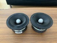
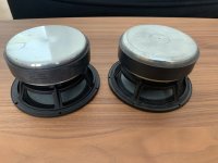
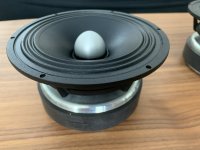
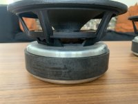
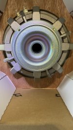
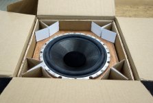
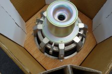
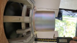
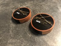
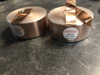
FS: 12" Acoustic Elegance Lambda Woofer Driver PB12 with Copper Faraday Rings - 320$
FS: 12" Acoustic Elegance Lambda Woofer Driver PB12 with Copper Faraday Rings - 150$ ( Single Woofer )
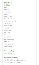
Woofer:
Acoustic Elegance Lambda Driver PB12 with Copper Faraday Rings in excellent shape.
The copper faraday decreases inductance and as a result distortion is decreased.
It has Xmax of about 15.5mm.
Parameters for the PB12:
Fs: 21hz
Qms: 4.2
Vas: 160L
Cms: .4mm/N
Mms: 143G
Rms: 4.5kg/s
Xmax: 15.5mm
Sd: 530sqcm
Qes: .32
Re: 3.5
Le: .3
Z: 4ohm
Pe: 500W
Qts: .3
1W SPL: 89dB
PB12 is the predecessor of SBP12.
SBP12 Highlights: (from manufacturer's website):
The SBP Series are also the ultimate option for automotive infinite baffle use. They have a larger motor then the IB-AU Series for more efficiency in the upper bass region where there is very little cabin gain. This allows them to integrate and work extremely well with the cabin gain in your vehicle. You will not find a lower distortion woofer for Automotive Infinite Baffle applications.
https://aespeakers.com/shop/sbp/sbp12/
http://www.aespeakers.com/Lambda001-1.php
Bought directly from:
Acoustic Elegance John E. Janowitz
http://www.aespeakers.com 1825 Mills St.
Phone: 920-469-9198 Green Bay, WI 54302
Mobile: 920-217-0625 Fax: 775-258-1406


Woofer:
Acoustic Elegance Lambda Driver PB12 with Copper Faraday Rings in excellent shape.
The copper faraday decreases inductance and as a result distortion is decreased.
It has Xmax of about 15.5mm.
Parameters for the PB12:
Fs: 21hz
Qms: 4.2
Vas: 160L
Cms: .4mm/N
Mms: 143G
Rms: 4.5kg/s
Xmax: 15.5mm
Sd: 530sqcm
Qes: .32
Re: 3.5
Le: .3
Z: 4ohm
Pe: 500W
Qts: .3
1W SPL: 89dB
PB12 is the predecessor of SBP12.
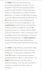
SBP12 Highlights: (from manufacturer's website):
- Lambda Motor with Full Copper Faraday Sleeve (FCFS)
- Extremely low and linear inductance
- Wide bandwidth and detailed midbass
- High Xmax with clean suspension travel
- High Efficiency upper/midbass
- Designed for sealed box applications
- Also ideal for Automotive Infinite Baffle use
The SBP Series are also the ultimate option for automotive infinite baffle use. They have a larger motor then the IB-AU Series for more efficiency in the upper bass region where there is very little cabin gain. This allows them to integrate and work extremely well with the cabin gain in your vehicle. You will not find a lower distortion woofer for Automotive Infinite Baffle applications.
https://aespeakers.com/shop/sbp/sbp12/
http://www.aespeakers.com/Lambda001-1.php
Bought directly from:
Acoustic Elegance John E. Janowitz
http://www.aespeakers.com 1825 Mills St.
Phone: 920-469-9198 Green Bay, WI 54302
Mobile: 920-217-0625 Fax: 775-258-1406
Remove crossfader on a DJ mixer
- By h3j
- Construction Tips
- 2 Replies
Hi,
I want to remove the crossfader on my Allen & Heath Xone 23 mixer. The crossfader itself is a 10k linear slide pot. To hear both channel 1 and channel 2 the pot needs to be in the middle. Not sure what the best approach is, however. How would you have solved it?
I want to remove the crossfader on my Allen & Heath Xone 23 mixer. The crossfader itself is a 10k linear slide pot. To hear both channel 1 and channel 2 the pot needs to be in the middle. Not sure what the best approach is, however. How would you have solved it?
Sennheiser EM300 G2 service software
- By FifIGBT
- Analog Line Level
- 1 Replies
Hello.
I have a EM300 G2 receiver with not working processor (power supply was checked, and radio part was checked in other working receiver). The processor gets the clock, but does not initialize display or anything. I think It was bricked during software update. I want to try to reprogram it through the DATA port (rs485) - the service manual says there is sennheiser software just to do this, but it is not avaible anymore. Is anybody able to give me te software or the .hex file (It says it was on cd sold with receiver).
Thanks
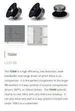
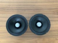
AE TD6M
One pair of Acoustic Elegance TD6M midranges. One is new and one was mounted on a baffle for evaluation. The evaluation driver had the mounting holes drilled to allow for flush mount screws. $300 CND for the pair. Prefer Canadian sale as I do not have PayPal or any method to accept international payment.
Attachments
-
 4A04B2E8-069D-41CC-9A0F-8DFE734D0375.jpeg434.2 KB · Views: 112
 -
 38E6AC2A-1338-46AA-9714-EA927E17DA8C.jpeg323.8 KB · Views: 107
 -
 6D0A9696-1C4F-4491-A079-49C5E2091AA1.jpeg284 KB · Views: 118
 -
 F7506A7D-01B7-4BB4-AD88-A10F4D695499.jpeg345.6 KB · Views: 105
 -
 91CE92C3-6A1C-4A9E-9EE8-B5170B7F6603.jpeg69.1 KB · Views: 100
 -
 264DBAF1-3416-407E-8859-30AB5AC3FED5.jpeg187.9 KB · Views: 108
 -
 F2D40F0C-0993-481A-A604-982755E20DE5.jpeg122.7 KB · Views: 101
 -
 30A64C89-5561-4383-99E1-D0F9ECD0D005.jpeg439.3 KB · Views: 115
 -
 788B187B-0DC6-4742-AF66-9488C4DF3C69.jpeg227.5 KB · Views: 101
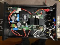
PPI PCX-2200 driver card
- By Oldskoolamps
- Car Audio
- 9 Replies
I am trying to repair a channel on this amp and found some shorts on the driver card and when I removed it the two suspects fell off the card. Should I try to replace them? What is the small one? Or should I try to build a new one? I found a company that sells replacement cards but they look different, how would I check what components go on the new card?
Attachments
13W*2 6P14/EL84 from ebay
- By Eliad
- Tubes / Valves
- 30 Replies
I got this kit from ebay.
13W*2 6P14/EL84 Push-pull HiFi Class AB Stereo Tube Integrated Amplifier DIY KIT | eBay
I put it together and i got stuck. When I turn the power on I get a loud high pitch noise, the actual audio if I get any is very little. I double checked the soldering I cant find where I made a mistake. The noise is on both channels. If i disconnect the negative feedback from the speakers output the noise goes away but there is no amplification of the audio signal. I am a NOOB. I must have made a mistake but I do not know where to look. I have enough knowledge to follow the markings on the PCB and to solder but I have no idea where to look for my mistake.
The build and schematics for this you can find it on
DJ100 Assembeld Manual_免费高速下载|百度网盘-分享无限制
Any suggestion will be greatly appreciated.
For Sale B&W 801 D4 10” woofers (BNIB)
Measured. Now NO LONGER FOR SALE:
(Shipping overseas ok but will cost a small fortune)
These are the genuine spare parts for the B&W 801 D4 loudspeaker. Made in England, in original B&W packaging.
10” woofers with massive neo magnet. 8 ohms.
At this stage EOI only: I’m not sure how to price these.
Total of 4 up for grabs.
(Shipping overseas ok but will cost a small fortune)
These are the genuine spare parts for the B&W 801 D4 loudspeaker. Made in England, in original B&W packaging.
10” woofers with massive neo magnet. 8 ohms.
At this stage EOI only: I’m not sure how to price these.
Total of 4 up for grabs.
Attachments
ML Ascent new ESL panels sound bad as old ESL ..
- By nedi
- Planars & Exotics
- 8 Replies
Hi all,
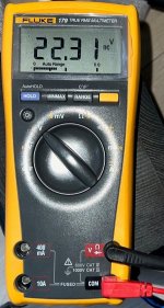
After my speakers were out of use for about a year, I noticed a loss of high frequencies and transparency. The year of production is 2002 and it was to be expected that it was time to replace the esl panels. Before buying new panels, I checked the bias DC voltage (1Gohm in series with a multimeter) and the voltage was 22.3V (2230V), also connection between step up transformer and front/rear stators. ML support confirmed that the voltage is within the expected range. I also checked the capacitors in the crossover. 10 years ago I replaced Solen and Benic with Duelund and Mudorf and the result was even more detail and a more natural sound. I also disconnected Jumper J1 to disconnect the "ML DEC" limiter circuit and the sound was still just as bad. I was sure the panels were faulty. After replacing the new panels, the sound did not change. I tried another amplifier, but no change in the sound. Then I ordered new step up audio transformers for both speakers but that didn't help either. I have no idea what to do. Is it possible that the new ESL panels are defect? ML support told me that every panel is tested before delivery. I tried another pair of speakers (they are not ESL, standard dynamic speakers) and the details, treble sone sound much better. I hope someone can give me some advice.
After my speakers were out of use for about a year, I noticed a loss of high frequencies and transparency. The year of production is 2002 and it was to be expected that it was time to replace the esl panels. Before buying new panels, I checked the bias DC voltage (1Gohm in series with a multimeter) and the voltage was 22.3V (2230V), also connection between step up transformer and front/rear stators. ML support confirmed that the voltage is within the expected range. I also checked the capacitors in the crossover. 10 years ago I replaced Solen and Benic with Duelund and Mudorf and the result was even more detail and a more natural sound. I also disconnected Jumper J1 to disconnect the "ML DEC" limiter circuit and the sound was still just as bad. I was sure the panels were faulty. After replacing the new panels, the sound did not change. I tried another amplifier, but no change in the sound. Then I ordered new step up audio transformers for both speakers but that didn't help either. I have no idea what to do. Is it possible that the new ESL panels are defect? ML support told me that every panel is tested before delivery. I tried another pair of speakers (they are not ESL, standard dynamic speakers) and the details, treble sone sound much better. I hope someone can give me some advice.
Attachments
6SN7/300B amp - channel imbalance
- Tubes / Valves
- 33 Replies
Hello all,
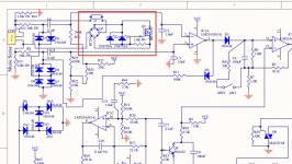
Could I prevail upon your collective brains again.... I'm looking at my buddies 300b amp - its an early 90s british model from Arion who seem to be long gone. Anyway, he's had a channel imbalance problem for a long time, and asked me to take a look.
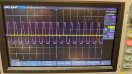
So the build quality isn't great, I found one or two cold solder joints, and a few resistors were certainly looking a bit tired, as they do when roasted. Nothing way off target though when comparing channel to channel. On the channel with lower output, I see distortion/reduced power creeping in quite early, and you can see this in the scope shot attached. Swapping valves between channels makes no difference.
I checked all resistors and replaced cathode coupling caps on the 6sn7 and 300b. I also replaced the 14K plate resistors on the 6sn7. The grid leak resistor on the 300b were very old looking carbon, and I replaced them as well. The volume pot shows a little channel imbalance, say if one track is 17.2k, the other will measure 16.9k but I don't see how that would reduce power output/balance given the distortion. The other oddity was the heaters for the 6sn7. It runs a 6VAC secondary, to a CRC of 4700uf-0r22-4700uf which only yielded 5.2V at the 6sn7 heaters which is very low) The first 4700uf was completely shot, but the second measured fine. I replaced that, and I now have 5.7V (dc) at the heaters but this seems too low to me still. I have 5.1V at the heaters of the 300b (this is a CRC supply).
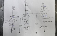
I drew out the schematic (attached below) with voltages marked in black and blue.
Anyone of you gurus see anything you would recommend me to look at?
Could I prevail upon your collective brains again.... I'm looking at my buddies 300b amp - its an early 90s british model from Arion who seem to be long gone. Anyway, he's had a channel imbalance problem for a long time, and asked me to take a look.
So the build quality isn't great, I found one or two cold solder joints, and a few resistors were certainly looking a bit tired, as they do when roasted. Nothing way off target though when comparing channel to channel. On the channel with lower output, I see distortion/reduced power creeping in quite early, and you can see this in the scope shot attached. Swapping valves between channels makes no difference.
I checked all resistors and replaced cathode coupling caps on the 6sn7 and 300b. I also replaced the 14K plate resistors on the 6sn7. The grid leak resistor on the 300b were very old looking carbon, and I replaced them as well. The volume pot shows a little channel imbalance, say if one track is 17.2k, the other will measure 16.9k but I don't see how that would reduce power output/balance given the distortion. The other oddity was the heaters for the 6sn7. It runs a 6VAC secondary, to a CRC of 4700uf-0r22-4700uf which only yielded 5.2V at the 6sn7 heaters which is very low) The first 4700uf was completely shot, but the second measured fine. I replaced that, and I now have 5.7V (dc) at the heaters but this seems too low to me still. I have 5.1V at the heaters of the 300b (this is a CRC supply).
I drew out the schematic (attached below) with voltages marked in black and blue.
Anyone of you gurus see anything you would recommend me to look at?
Attachments
2-way into 3-way cannibalized crossover query
Any crossover wizards able to suggest if this could work?
Have some compartmentalized reflex cabinets - 15l upper & 32l lower.
Hope to fit Tannoy V6 drivers in the upper with Peerless SLS-P830667 woofers in the lower.
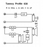
I have the original 2 way V6 crossovers and a pair of Tannoy 638 3 way crossovers (schematics attached).
Would you start from scratch or could these be cobbled into a viable crossovers?
Grateful for any advice.
Have some compartmentalized reflex cabinets - 15l upper & 32l lower.
Hope to fit Tannoy V6 drivers in the upper with Peerless SLS-P830667 woofers in the lower.
I have the original 2 way V6 crossovers and a pair of Tannoy 638 3 way crossovers (schematics attached).
Would you start from scratch or could these be cobbled into a viable crossovers?
Grateful for any advice.
Attachments
Raysonic CD-128 - Tube output buffers
- By LJT
- Tubes / Valves
- 0 Replies
The Raysonic CD-128 has single ended RCA and balanced XLR outputs. All outputs buffered by tubes and subjectively I'm quite pleased with the sound.
Unfortunately I have not been able to source the schematics, however as far as I've been able to tell it uses one set of OPA-2604 for buffering/filtering the DAC (PCM 1732M) and a second set of OPA-2604 for generating the balanced signals.
As mentioned, all six outputs are buffered by 6922EH tubes. The PSU for the tubes are marked 90v on the PCB (probably AC). Full wave rectified and with a single 220uF/220v capacitor. Tracing the tube section it seems that the XLR outputs are buffered with a simple cathode follower (one tube each XLR). The RCA output seem to be bufferd with a "white cathode follower".
I would appreciate if anybody can provide feedback on any of the following:
1 - Does anyone know where I could source service manual / schematic for this player?
2 - At this low voltage (estimated 50v/tube on the white follower) does these buffers serve a purpose or are they to be considered "effect box"?
3 - Are some tubes more suited for low voltage operation than others. The player come with EH tubes, but I also have NOS 6922 from GE and various NOW Phillips PCC and ECC-88 (of 3 various getter design)
ECL86, rebuilding a 1969 tube radio as a SE amp -- a beginner project, help (ecl-86)
- By jeepe
- Tubes / Valves
- 2 Replies
hi,
I'm very new to this, the tube amp thing... as well as to this forum, .. and high voltages... I'm a guitarfxlayout guy, using vero board...
BUT I happen to have a radio... 🙂 and it works... and it is pretty well documented....
and it even has a "Q" input into which I could plug a pedal...
But I want more 🙂
want to learn beforehand... and I'd like to bring out more from this...
I'd like to strip off the amplifier part....
okay, first I want to use it... for a week or so...
then I'll try to strip it off...
first using pliers, or a solder iron, to cut off the rest of the circuit..
measuring perhaps voltage at certain points (B1+ B2+) in the new situation.... (I'm new to high voltage, so I'm psyching up, watching videos, reading, etc 🙂 )
and then...
rebuild it from scratch...
my question is what do you experienced guys / girls think of this?
I am learning.... and I can already say that I understand 80% of all stuff I read about simple tube amps...
But I'm miles away from committing designer decisions... if it will every happen... not very likely...
my plan is to keep the EZ80 rectifier so that the voltage would not rise even further regarding that it was designed for 220V, and now it is 230V that Europeans have in their wall sockets... and tube amp builders say that it is even more sometimes...
I'd not want to have a tone stack.. it will have a volume pot only...
two tubes and two transformers...
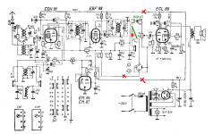
I attach the schematic with my "cut off plan".... and also my "rebuild" layout plan
for any suggestion I'll be grateful 🙂
Peter
I'm very new to this, the tube amp thing... as well as to this forum, .. and high voltages... I'm a guitarfxlayout guy, using vero board...
BUT I happen to have a radio... 🙂 and it works... and it is pretty well documented....
and it even has a "Q" input into which I could plug a pedal...
But I want more 🙂
want to learn beforehand... and I'd like to bring out more from this...
I'd like to strip off the amplifier part....
okay, first I want to use it... for a week or so...
then I'll try to strip it off...
first using pliers, or a solder iron, to cut off the rest of the circuit..
measuring perhaps voltage at certain points (B1+ B2+) in the new situation.... (I'm new to high voltage, so I'm psyching up, watching videos, reading, etc 🙂 )
and then...
rebuild it from scratch...
my question is what do you experienced guys / girls think of this?
I am learning.... and I can already say that I understand 80% of all stuff I read about simple tube amps...
But I'm miles away from committing designer decisions... if it will every happen... not very likely...
my plan is to keep the EZ80 rectifier so that the voltage would not rise even further regarding that it was designed for 220V, and now it is 230V that Europeans have in their wall sockets... and tube amp builders say that it is even more sometimes...
I'd not want to have a tone stack.. it will have a volume pot only...
two tubes and two transformers...
I attach the schematic with my "cut off plan".... and also my "rebuild" layout plan
for any suggestion I'll be grateful 🙂
Peter
Attachments
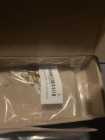
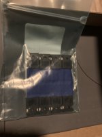
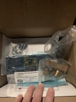
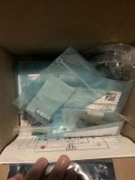
Amp camp amp kits (200$)
I have two amp kits that are mostly assembled. Unfortunately need to sell them. Just the electronics (no chasis)I have a few xtra components also. Both sets come with 8 matched mosfets Irfp240 that was purchased from a guy i believe his name was thatcher on this site. Also the kits were upgraded with better parts from another guy on this site also… you can see in the pics whats for sale and how far i got with them. The pictures of the parts in the box is just xtra from when i ordered the parts. Also have hakko solder iron and kester solder if interested. Thanks for looking! 200$ or best offer!!…… sold
Attachments
-
 240C27A5-8C46-4A30-9F5C-129C0C1391FD.jpeg458.5 KB · Views: 146
 -
 C1EF66FD-A9D7-474E-A660-ED7A938C70E3.jpeg413.1 KB · Views: 140
 -
 664270D8-66B1-4B00-8077-72691E84E667.jpeg399.8 KB · Views: 134
 -
 D4A47284-AEAF-4068-A8E3-CBB9E3D3E32F.jpeg352.6 KB · Views: 129
 -
 8E5D805B-07D7-440D-8092-64F0D965FB03.jpeg332.2 KB · Views: 121
 -
 4335CF60-671B-4D4D-82D0-98BC3BB14F93.jpeg335.1 KB · Views: 126
 -
 72BC4D73-753F-40BB-A9AC-C8F421D64B6C.jpeg374.9 KB · Views: 118
 -
 64189314-B855-4A69-BFF2-8934561D91F1.jpeg402.6 KB · Views: 126
 -
 6EA889ED-3CC5-49CA-A80A-AC01D02BD82F.jpeg322 KB · Views: 113
 -
 6C46E96F-1B65-4716-800A-143C08999B5F.jpeg410.3 KB · Views: 125
 -
 516A40D3-C07B-40AB-B130-195B45517DC4.jpeg368.4 KB · Views: 139
First valve amp project
- By peacocksuit
- Tubes / Valves
- 3 Replies
Edited
Duplicate thread please delete!
Duplicate thread please delete!
Germanium transistors, all hype or worth it?
- By parkerdiy
- Solid State
- 35 Replies
I'd like to build a simple germanium preamp. I already have a lot germanium transistors.
Are there any sonic benefits to germanium or is it all hype?
Are there any sonic benefits to germanium or is it all hype?
a few hard for me to find trust able answers
- By mrorionrob
- Pass Labs
- 6 Replies
does anyone here have the power voltage rail, and capacitance for the power supply section? and does it require center tapped secondary transformer? thanks in advance
Looking for components
1. Found! On Semi or even TI NPN 40W TIP50G
2. Found! Hi Voltage Linear Regulator LR8N3-G TO-92 Microchip Tech/Atmel
Need (2) or more of each.
Will pay well or even make trade you'll like.
Can't seem to find genuine to finish AWA Capacitor Leakage Tester
Thks,
Charles
2. Found! Hi Voltage Linear Regulator LR8N3-G TO-92 Microchip Tech/Atmel
Need (2) or more of each.
Will pay well or even make trade you'll like.
Can't seem to find genuine to finish AWA Capacitor Leakage Tester
Thks,
Charles
Extending Bluetooth antenna range?
I have this a chip amp with Bluetooth mounted inside a weatherproof metal cabinet, which is outside. That drastically reduces the Bluetooth range.
The antenna looks like this one:

Can anyone think of some clever way to move the antenna outside the amp, or to extend it's range?
The antenna looks like this one:
Can anyone think of some clever way to move the antenna outside the amp, or to extend it's range?
Folded Cascode RIAA Tube Preamp
- By wrenchone
- Analogue Source
- 15 Replies
I'm tinkering with the concept of putting together a passively equalized RIAA vacuum-state preamp using folded cascode gain cells. I'm doing my current design using 8CG7. That's a nice, linear tube but not likely the best noise-wise. I am open to suggestions for alternate tube types to use in the design. The design would incorporate a 40X input stage, EQ, then a 30X output stage, which gets you ~40dB of gain at 1kHz, good for MM cartridges.
I'm toying with the idea of using 6AM4, a tube championed by Vinylsavor at his blog site. However, given that the transconductonce of that tube is much higher than the 8CG7, I will end up with a load resistor on the lowish side for the gains I'm contemplating, and consequently some fairly bloated values for the EQ capacitors - maybe not a real problem, but still a consideration. Thoughts?
I'm toying with the idea of using 6AM4, a tube championed by Vinylsavor at his blog site. However, given that the transconductonce of that tube is much higher than the 8CG7, I will end up with a load resistor on the lowish side for the gains I'm contemplating, and consequently some fairly bloated values for the EQ capacitors - maybe not a real problem, but still a consideration. Thoughts?
-
Locked
Reasonable Beginner Bass Amp/Speaker from a Sub and a Speaker?
- By Crocobar
- Instruments and Amps
- 130 Replies
Hi All!
My daughter just started taking bass lessons, currently using Squier PJ bass with a simple Squire guitar amp that came as a part of a bundle with my Squire Strat (I am also a beginner).
I have an old subwoofer from a 4.1 system, and an all-purpose speaker (from CostCo - they used to sell these weird wedge-shaped three-way speakers, I bought it some years ago to try as a center channel).
I am thinking to hook up this woofer and this speaker to some simple PA board to make an entry-level Bass amp for her. Perhaps something based on a TPA3116? Is this reasonable at all or I would be better off just buying some cheap bass amp/speaker?
Thank you!
Could you analyze this crossover a bit?
So admittedly I know very little, have few tools and would like some basic help with understanding and improving this particular crossover.
It's for a ported 3-way with two 8ohm 6,5" bass woofers in parallel, a 4ohm 4" or 5" aluminium midrange and a 4 ohm 1" soft-dome tweeter. It's from a reputable, well-known speaker manufacturer.

I just upgraded all caps to mostly ClarityCap CSA, the 100uf, 33uf and 22uf were NPEs before so the ESR ratio changed there - maybe there's a bit too much high-mid to treble output. Or it was just congested before? Then again, I trust this speaker was originally voiced to NOT be congested.
The coils would be next - here's what I would want to do if I had money:
A Jantzen C-coil for the bass, copper foils for the rest. That would be about 400 euros. Where would you see no need for a foil coil here? I made the hypothetical shopping list keeping in mind the coil resistances so that the ratio of resistance decrease from the originals would be approximately proportional, which adds some expense, considering the C-coil is down to 0,07ohms.
Do you see that I should maybe try any bypass capacitor "magic" here, in what value? Anything I should attempt especially to lessen/avoid fatigue?
I don't mind that I need to learn to design a new speaker essentially now that I changed anything, that's pretty much ideal but I need some tips.
I don't fully understand this design as it is, either. What order is the midrange circuit? Is it a 3rd order with a correction filter, or a 4th order? There is no resistor in line with the 22uf and 0,018mH so is it then not a notch filter?
I understand that I'm asking too much to analyze this without knowing more but I just need something thrown to me, until I can afford a DATS, and so forth.
Anything.
It's for a ported 3-way with two 8ohm 6,5" bass woofers in parallel, a 4ohm 4" or 5" aluminium midrange and a 4 ohm 1" soft-dome tweeter. It's from a reputable, well-known speaker manufacturer.
I just upgraded all caps to mostly ClarityCap CSA, the 100uf, 33uf and 22uf were NPEs before so the ESR ratio changed there - maybe there's a bit too much high-mid to treble output. Or it was just congested before? Then again, I trust this speaker was originally voiced to NOT be congested.
The coils would be next - here's what I would want to do if I had money:
A Jantzen C-coil for the bass, copper foils for the rest. That would be about 400 euros. Where would you see no need for a foil coil here? I made the hypothetical shopping list keeping in mind the coil resistances so that the ratio of resistance decrease from the originals would be approximately proportional, which adds some expense, considering the C-coil is down to 0,07ohms.
Do you see that I should maybe try any bypass capacitor "magic" here, in what value? Anything I should attempt especially to lessen/avoid fatigue?
I don't mind that I need to learn to design a new speaker essentially now that I changed anything, that's pretty much ideal but I need some tips.
I don't fully understand this design as it is, either. What order is the midrange circuit? Is it a 3rd order with a correction filter, or a 4th order? There is no resistor in line with the 22uf and 0,018mH so is it then not a notch filter?
I understand that I'm asking too much to analyze this without knowing more but I just need something thrown to me, until I can afford a DATS, and so forth.
Anything.
B&K ST-140 updated circuit board trouble shooting
- By derrek01
- Solid State
- 0 Replies
I have recently had some prototype circuit boards made using the ECX10N20 and ECX10P20 lateral MOSFETs. I have for the most part copied the original B&K st-140 circuit boards. I only made Minor changes like adding additional filter caps, and I used larger copper traces and 2 layers instead of the original single layer board. I used all quality components like dale resistors and nichicon caps. The amplifier sounds great compared to the original except I am getting a audible clipping sound and fairly high volume levels. I accidentally figured out that if I place my DMM leads on the source of the n channel MOSFET and the ground connection on the circuit board the problem completely goes away. I don't understand what's happening. I'm not a engineer just a electrical technician.
Attachments
db_Mark XCA series active crossovers
- By Damo s
- PA Systems
- 3 Replies
Hi,
Does anyone have much experience with these db-Mark XCA series cross overs (bluearan sell them)?
I'm currently using a Xilica XP3060, Its a great unit and Im happy with it, but they no longer sell them and I'd like a back up in case this unit packs up mid show. I know its pretty unlikely, but you never know. I had considered purchasing either a new 2040 or 4080 and then just use 2 units all the time, one for each channel (the 2040 would do here for one channel of a 4 way system) . If one was to fail then I could just split off the other and run in mono (via a patch panel with parallel XLR outputs to allow a quick change over)
Alternatively, I could just sell the Xilica unit and buy two of the XCA units, but it depends how good they are sound wise. I have not had anything to directly compare but one of the reasons I bought the Xilica was because all reports were saying that sound quality was great compared with the cheaper units.
Budget wise I'd rather spend as little as possible to achieve having a back up unit, but the sound quality as is important. if it means buying another Xilica then so be it, but if the verdict is that the XCA's are actually just as good then I may as well go down that route. (not to mention I might have some fun getting support for the Xilica if it needs repairing, should it go wrong).
Thanks in advance.
Why classic shorts test doesn't kill some tubes?
- By Elerion
- Tubes / Valves
- 10 Replies
Hi everyone!
I wonder why the classic shorts/leak test using neon bulb doesn't kill some tubes due too high voltage between electrodes (particulary grid-cathode and cathode-heater).
As one picture is worth a thousand words, here's a simple model schematic and waveforms.
This is the situation when grid is on the hot side and all the other elctrodes are in the cold side, so to speak.

If using 115 Vac power source, about 280 V peak voltage are present between grid and cathode. Isn't this too much?
Vgk max for some signal triodes is 50 V according to datasheet.
What am I missing here?
Thank you!
I wonder why the classic shorts/leak test using neon bulb doesn't kill some tubes due too high voltage between electrodes (particulary grid-cathode and cathode-heater).
As one picture is worth a thousand words, here's a simple model schematic and waveforms.
This is the situation when grid is on the hot side and all the other elctrodes are in the cold side, so to speak.
If using 115 Vac power source, about 280 V peak voltage are present between grid and cathode. Isn't this too much?
Vgk max for some signal triodes is 50 V according to datasheet.
What am I missing here?
Thank you!
Broken tweeter wire for SB Acoustics SB13PFC24-4 COAX. Possibility of repair?
- By darksideboy
- Multi-Way
- 8 Replies
Hi Members,
I am in the position to buy a pair of used an SB Acoustics SB13PFC24-4 COAX. Although the speakers look like they are in good cosmetic conditions, one of the tweeter wires has broken right at the tweeter screw point (please refer to the images).
Could someone tell me if this can be fixed without much hard work (for instance unscrewing the back and reconnecting the wire) - and any instructions on this?
I am really really interested in buying these drivers but not being able to have the tweeter working on one of them seems like a total deal breaker.
I would really appreciate any help from wise members on this.

.jpeg")

I am in the position to buy a pair of used an SB Acoustics SB13PFC24-4 COAX. Although the speakers look like they are in good cosmetic conditions, one of the tweeter wires has broken right at the tweeter screw point (please refer to the images).
Could someone tell me if this can be fixed without much hard work (for instance unscrewing the back and reconnecting the wire) - and any instructions on this?
I am really really interested in buying these drivers but not being able to have the tweeter working on one of them seems like a total deal breaker.
I would really appreciate any help from wise members on this.
Help from Spain
- By blek stena
- Swap Meet
- 13 Replies
Hi,
I'm looking for someone to help me buy some drivers from Spain store that ships only in Spain and i'm in Croatia.
Thanks,
I'm looking for someone to help me buy some drivers from Spain store that ships only in Spain and i'm in Croatia.
Thanks,
Advice on cabinet tuning for multiway system
- By Nut84
- Subwoofers
- 0 Replies
Hello,
I'm new to this forum, although have been reading a lot of posts on here, but now need to reach out for some specific help! I wasnt sure if this was the right forum or if it should be in the multiway area?
I have been designing a system that is quite large, and am right about at the stage to build test cabs to take measurements from to then fine tune before the actual build begins.
I have been doing as much homework as possible over the past couple of years, reading, researching, and recently plotting on WinISD.
But have some questions regarding tuning and cut offs of the bass cabs and how they should work together that I cant find the answer too, or rather get my head around!
The system will be a 4-way to be used as a pa at various small events and eventually finding a permanent home in a venue.
The drivers are as follows:
Sub: JBL 2241G
Mid Bass: TAD 1601A
Mid High: Altec 299 mated to JBL 2360a Horn (I will also build and test multicell horn in future)
High: JBL 2405
These will be bi-amped with active crossover / DSP
The actual construction / carpentry design of the cabs is not an issue at all, but rather the physics of tuning and cut off etc.
Because I have taken T&S parameters from each driver using DATS V3, there are slight differences between the two JBLs and the two TADs. So I have plotted all 4 drivers in WinISD to get a good median design. The parameters also differ from the official JBL literature.
JBL 2241G:
My parameters:
Fs 44.18Hz & 40.51Hz
Vas 271L & 318L
Qts 0.48 & 0.44
Official:
Fs 35Hz
Vas 310L
Qts 0.40
TAD 1601a:
My parameters:
Fs 32.33Hz & 33.24Hz
Vas 394L & 388L
Qts 0.37 & 0.38
Official:
Fs 28Hz
Vas 307L
Qts 0.34
The differences between the respective drivers when plotted in WinISD with the same tuning and volume are minimal, so I am not too worried about that.
Below are some screen shots from WinISD for both the JBL (Yellow) and TAD (Blue).
Current enclosure plots are:
JBL 2241G - 300L / 38Hz
F3 around 39Hz
TAD - 150L / 35Hz
F3 around 48Hz
Transfer Function

Group Delay

Rear Port Velocity

I am not completely fixed with the volume or tuning, and I am sure these will change after some input from others. size of enclosures is not an issue either.
Obviously this does not take into account where the x-over points will be, and that is where I need some advice: The relationship of tuning depending on x-overs
I can see that both the JBL and TAD drivers are not too dissimilar with what can be achieved.
The 18" JBL will purely be for the additional low end, where as the 15" TAD will be crossed higher for mid bass, which is not plotted. crossover point are yet to solved / decided!!
Say for example I crossed these drivers at 100hz (that may be completely wrong) Does that mean I do not have to worry so much about the tuning of the 15" TAD as it will cut off above tuning? How will this affect tuning and response etc?
Should I be designing with crossover points in mind? and too what degree or tolerance?
I also have read differing info on whether to tune above or below F3?
And how does tuning the enclosure relate to the Fs? Does it matter how close they are?
Any help or advice is very much appreciated.
I have tried to clearly explain as much as possible!
Thank you
I'm new to this forum, although have been reading a lot of posts on here, but now need to reach out for some specific help! I wasnt sure if this was the right forum or if it should be in the multiway area?
I have been designing a system that is quite large, and am right about at the stage to build test cabs to take measurements from to then fine tune before the actual build begins.
I have been doing as much homework as possible over the past couple of years, reading, researching, and recently plotting on WinISD.
But have some questions regarding tuning and cut offs of the bass cabs and how they should work together that I cant find the answer too, or rather get my head around!
The system will be a 4-way to be used as a pa at various small events and eventually finding a permanent home in a venue.
The drivers are as follows:
Sub: JBL 2241G
Mid Bass: TAD 1601A
Mid High: Altec 299 mated to JBL 2360a Horn (I will also build and test multicell horn in future)
High: JBL 2405
These will be bi-amped with active crossover / DSP
The actual construction / carpentry design of the cabs is not an issue at all, but rather the physics of tuning and cut off etc.
Because I have taken T&S parameters from each driver using DATS V3, there are slight differences between the two JBLs and the two TADs. So I have plotted all 4 drivers in WinISD to get a good median design. The parameters also differ from the official JBL literature.
JBL 2241G:
My parameters:
Fs 44.18Hz & 40.51Hz
Vas 271L & 318L
Qts 0.48 & 0.44
Official:
Fs 35Hz
Vas 310L
Qts 0.40
TAD 1601a:
My parameters:
Fs 32.33Hz & 33.24Hz
Vas 394L & 388L
Qts 0.37 & 0.38
Official:
Fs 28Hz
Vas 307L
Qts 0.34
The differences between the respective drivers when plotted in WinISD with the same tuning and volume are minimal, so I am not too worried about that.
Below are some screen shots from WinISD for both the JBL (Yellow) and TAD (Blue).
Current enclosure plots are:
JBL 2241G - 300L / 38Hz
F3 around 39Hz
TAD - 150L / 35Hz
F3 around 48Hz
Transfer Function
Group Delay
Rear Port Velocity
I am not completely fixed with the volume or tuning, and I am sure these will change after some input from others. size of enclosures is not an issue either.
Obviously this does not take into account where the x-over points will be, and that is where I need some advice: The relationship of tuning depending on x-overs
I can see that both the JBL and TAD drivers are not too dissimilar with what can be achieved.
The 18" JBL will purely be for the additional low end, where as the 15" TAD will be crossed higher for mid bass, which is not plotted. crossover point are yet to solved / decided!!
Say for example I crossed these drivers at 100hz (that may be completely wrong) Does that mean I do not have to worry so much about the tuning of the 15" TAD as it will cut off above tuning? How will this affect tuning and response etc?
Should I be designing with crossover points in mind? and too what degree or tolerance?
I also have read differing info on whether to tune above or below F3?
And how does tuning the enclosure relate to the Fs? Does it matter how close they are?
Any help or advice is very much appreciated.
I have tried to clearly explain as much as possible!
Thank you
Attachments
DAC chip help
- By bobcat
- Solid State
- 2 Replies
Hi all desperatly looking for a Dac chip part number lv4930m 44 pin cannotfind any reference to it on the net it is from a bose L1rev 2 bose code in parts list is 3132-3061any help greatly recieved B/Cat
An AF Power Amplifier with Crossover Feedback
- By OldHector
- Tubes / Valves
- 5 Replies
This 1965 paper was discussed on the UK Vintage Radio site, but did not get many comments, and I wondered if it would appeal to some of the more technical DIYers here.
It describes a novel solution to create a 'laboratory' amplifier with a distortion limit of 0.1% over an extensive audio range. The solution uses a mixture of feedback from the OPT Primary and Secondary, with a small transformer working with high and low pass filters to solve the problem of a non ideal OPT.


It describes a novel solution to create a 'laboratory' amplifier with a distortion limit of 0.1% over an extensive audio range. The solution uses a mixture of feedback from the OPT Primary and Secondary, with a small transformer working with high and low pass filters to solve the problem of a non ideal OPT.
Attachments

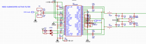
Subwoofer Active Filter Help?
- By kgray9
- Analog Line Level
- 19 Replies
Hello all! Newbie here.
I am planning on using the TPA3255 in PBTL mode to drive a subwoofer. I need help with a subwoofer filter design though on the analog input.
I am thinking of using the OPA1612AIDR , which seems really nice lol. For some reason though, I can't figure out how to make a simple active subwoofer (100hz) low pass filter. I am hoping for a -20dB/decade drop, but more would be great also.
I would really appreciate any tried and proven circuits, or ideas, tips, etc.
Thanks in advance!
Edit:
Attached is my current TPA3255 circuit. (I know it is pretty rough. I drew it quite a bit ago.)
Attachments
Copland CDA288 drawer alignment issue
- By turborat
- Digital Source
- 4 Replies
Hi,
I have a Copland CDA288 that I've just replaced all the broken drive gears in as the drawer suddenly stopped opening/closing properly. Unfortunately no matter what position I try to align the tray to when pushing it back in, it simply doesn't want to work properly when powered up. Without the top tray assembly on the mechanism, the drawer seems to open/close ok but as soon as I re-fit the top tray assembly, it has the issue that you can see in the video here - https://photos.app.goo.gl/9wkttRje7ohxQdvK6
Does anyone know how to re-align these trays correctly so I can try and get it going again as it's a lovely player.
Thanks
Most basic Ian Canada setup
- By henrik2h
- Digital Line Level
- 6 Replies
Hi, stumbled upon this forum when searching for a new dac hat for pi. Maybe I am in the wrong place but am only looking for a rough opinion so I know if investigating further is worth it.
Was initially looking for an Allo Boss but found this gear from Ian Canada that looks promising. Somewhat hard to know exactly what I need to build the first and basic version of a dac with this. Would the enclosed 3 parts (and pi) be enough to have it functioning in a good way? Like the fact that it could be upgraded further on.
And second, and most important, would this be a "substantial" sound improvement over the Allo Boss if using average hifi gear (Hegel H80/Q Acou. 3020i)?
Bias trim
- By Arenith
- Solid State
- 2 Replies
I have on loan temporarily an Onkyo A-9050 until my Electrocompaniet is fixed.
It has these tiny cheap rotating things inside, one for each channel, which change the values across large three-legged resistors and if I turn them all the way to one direction, they make the transformer buzz.
I already touched them and don't know the original intended position. Now I'm not sure if the really shrill sound is due to the adjustment or just characteristic to this amplifier.
Anyway, how would I find out the best position for these? This amplifier is a "three-stage inverted Darlington" circuit, so is it not so clear compared to other designs, what the best value is and where? Is it even necessarily the same as "bias trim" in this case?
Originally I touched them to find out if they'd change the measured quiescent current at the terminals. They didn't affect it.
How should my speakers be stuffed
I have had my Comeau designed WD25TEx for years and"just for a change" I decided to carry out a suggested modification, namely : : To "skeletise" a bit more, the 19mm mdf main brace which is not only pretty close to the Seas AR26SE4 mid bass driver but also parallel to it so , it "seemed like a good idea" as perhaps the reverse wave rebounding off the solid parts of the brace might be adversely affecting the paper cone, linearity and detail.
So, I have drilled out 2 more 63mm holes on either side of the existing one which receives and helps fix the driver magnet in place and am pleased with the immediate effect seeming to extend output at either extreme, revealing more detail. Jazz trios sound much. much better and classical orchestras seem to have more individual strands but at the price that voices have hardened a bit.
At the same time, I must admit that my speakers were never "ideally" stuffed. Living abroad it was a question of using the materials at hand, namely thick carpet felt and Monacor polyester "dacron" stuff. I suspect I used too much of the latter and therefore would be grateful for a couple of guidelines on how best to go about it. The boxes themselves are made of 19mm particle board dressed outside with 5mm mdf to allow a uniform surface forspraying. I think that with 3 braces, Arboseal sealant all over the place and thickish carpet felt they are pretty well damped and sealed. I am wondering if by changing the dacron for something more suitable, I might ameliorate the slight hardness I am now hearing without needing to open the crossover can of worms. although Peter himself suggests playing with the 2R2 resistor in series with the 0.42mH inductor for added warmth.
The final complication is that the box itself is divided into 2 compartments which communicate via an aperiodic vent consisting of 3 lozenge shaped holes which originally used specifici foam (80 ppsi) as a suitable filter - mine has crumbled to dust - no idea why so I use some thin fibre glass wadding which seems to work well.
Is it a question of just "suck it and see" or are there any rough guidelines for sealed boxes and/or aperiodic ports ?
Electrocompaniet Output transistor replacements
- By 61051
- Solid State
- 0 Replies
Hi All,
I wounder if anyone had updated the output transistors for the EC25W amplifier - I currently use BD911 and BD912, but wondered if there was anything else suitable which would give the same result at a lower quiescent current ?
Many Thanks
Joe
I wounder if anyone had updated the output transistors for the EC25W amplifier - I currently use BD911 and BD912, but wondered if there was anything else suitable which would give the same result at a lower quiescent current ?
Many Thanks
Joe
Audible Physics RG100 wide band drivers
Selling a pair of Audible Physics RG100 drivers. Very high quality wide band drivers with very linear response. 100mm (3.9") size.
.jpg")
More info about the driver here: https://www.slaacoustics.com/produc...hm-wideband-driver-pair?variant=3009953005608
I think the version I have has an impedance of 6 Ohm. I can check this if it's needed.
Price: $400 plus shipping cost (shipped from Norway. Comes with a grille which is removable.
bomholt@gmail.com
Here's the raw response (no EQ) in a speaker baffle with 1/24 oct. smoothing:

I can send the outdrawing of the driver (PDF).
Datasheet seen here:

.jpg")
.jpg")
.jpg")
.jpg")
.jpg")
Contact me: bomholt@gmail.com
More info about the driver here: https://www.slaacoustics.com/produc...hm-wideband-driver-pair?variant=3009953005608
I think the version I have has an impedance of 6 Ohm. I can check this if it's needed.
Price: $400 plus shipping cost (shipped from Norway. Comes with a grille which is removable.
bomholt@gmail.com
Here's the raw response (no EQ) in a speaker baffle with 1/24 oct. smoothing:
I can send the outdrawing of the driver (PDF).
Datasheet seen here:
Contact me: bomholt@gmail.com
Internal switch in Krell KSA S-series to power on and off via AC wall outlet
- By qeter
- Solid State
- 2 Replies
Hello
According to the Owner Manuals of the Krell power amp KSA S-series there is the possibility to switch it into a Remote Turn On Installation. Meaning that the Krell can be switched on and off by an AC power outlet with a mains switch and bypassing the On/Off-switch on the front plate.
To make this change something has to be done in the inside of the Krell (little switch?). Does anybody know how the Remote Turn On Installation can be done.
I want to hide the amp and switch it via the AC wall socket.
Could i fold the Pencil 7HD?
- By rjbell
- Full Range
- 22 Replies
Rather than a tower i would like to build a short stout speaker on a low tilted stand for a vintage look. Could I just fold the Pencil 7 length in half or would this mess things up? It would obviously have a wider baffle.
Something like this
Login to view embedded media
Something like this
Login to view embedded media
iixo Impedance Inverter Cross Over
- Multi-Way
- 0 Replies
The iixo is a subtractive cross over suitable for horn systems I came up with a while back and have used for several years. I have made a few for other people and others have made their own with good results. While it has all the limitations of a 1st order xo in terms of excursion, (see threads here on diyAudio), with a suitably robust driver and horns and low power requirement it integrates a bass horn with a mid-upper horn very well, and provides the attenuation for the upper driver.
The iixo is nothing more than a low pass inductor in series with the bass driver, with a secondary winding to feed the upper driver. It is a transformer and the turns ratio sets the attenuation. The inverse of the signal across the bass driver appears across the inductor, since the output of the amplifier is flat.
The iixo requires there be a minimum step down ratio, of at least -6 to -9dB. More on this later, but you cannot get a 1:1 output. Attenuation is usually required for the upper horn and you can include a number of taps on the secondary to adjust this.
The iixo models and measures as expected with resistive loads but things change once you include the voice coil reactance. The bass driver requires a Zobel, which is no surprise. Another issue is that inductor coils with iron cores do not have constant inductance with frequency. A cheap LCR meter reading at 1kHz may not be the same reading given by a meter that can be set to 100Hz. But there are ways to wind a coil and choose a core that is much more constant.
The signal across the inductor can be taken to a second amp, and then you can have a 2nd order or greater slope. I got the idea for the iixo from jc morrison’s subtractive xo where he takes the signal across a high pass cap to a second amp. The iixo has the advantage of no cap and single amp.
I encourage anyone to try this simple idea, just wind a secondary on top of a LP inductor. I do some interleaving but it is not critical. If you don’t know the turns you can use the ratio of inductance which is the square of the turns ratio. I would welcome any comments. Also any history, as hard to believe I am the first. I nearly fell off the Listening Chair when I thought of it! But nobody has yet told me of any and I sent it to jc and others notorious. I have put it up on my website here:
https://www.azurahorn.com/azurahorn_system.html
Bi-amplificatio configuration
- By neddy999
- Solid State
- 4 Replies
Is there an accepted best practice(assuming two way speakers); use each amplifier for each channel or use one amplifier for the bass/mid and one for the treble? Thanks
First crack at LTSpice: guidance on GK preamp
- By szegedin
- Software Tools
- 1 Replies
I downloaded LTSpice and I'm on day two of learning how to use it. I am working on modeling the preamplifier section of my Gallien-Krueger 200RB bass amp, discussed in another thread (or two). My knowledge of electronics is very limited so:
Could use some help understanding LTSpice:
1. How do I make the op-amps the correct values? The amp has LF535N and LF351N op-amps. I placed generic ones in there as a placeholder. It seems like the amp uses only three leads from the opamp?
2. LTSpice seems to be missing some basic components; how can I insert a mechanical (not voltage-controlled) switch such as the ones used here for lo-cut, etc? I downloaded and used a potentiometer from a third-party.
3. LTSpice does not include the exact diodes in this amp (IN759). Can I substitute any other diode with vbreakdown=12v?
4. Are my J113 JFETs "wired" right?
I glossed over a couple other things in this schematic for now, such as grounds at input jacks (how to do this?) and the effects send/return.
Any help on any of these questions or feedback on how this looks so far would help me get down the road. 🙏
I'm attaching the LTSpice file, the original schematic, and the spec sheet for the op-amp.
Attachments
Replacement of Spring-Clip Speaker Terminal
- By patknk939
- Everything Else
- 11 Replies
I'm planning to replace a snap-on spring-clip speaker terminal(picture attached) with binding posts. Do I just simply desolder the spring-clip terminal and then with jumper wires connect the in/out points on the PCB to the relevant binding posts? Reason for asking is that when I looked at the metal connectors on the back of the terminal, each one is connected separately to the PCB. However, when I checked, with continuity by a multi-voltage meter, each insert hole with the solder points on the PCB, it showed that the +ve and -ve are connected, which had me confused because with binding post terminals, they are separated from each other and should be not connected. So, I may be ignorant of the spring-clip terminal construction or there is something I should pay attention to for such replacement. I'd appreciate any advice. Thanks.

Full DIY CD Transport based on old SANYO pickup
- By dxx573k
- Digital Source
- 38 Replies
Hello.
I am a owner of 2 similar CD Transport/Player – C.E.C. CD3100 and Parasound CBD2000.
One time, the CD3100 is broken with damage of microcontroller. I took microcontroller board from Parasound and place it to CD3100
During repairing process, I build full new CD transport – new controller (ATMEGA32), new software on ARDUINO IDE, new servo board, new power supply. I only took the box and laser pickup from original device.
The work started at june 2020 and finished only now.
I post the result here.
The new and old mainboard


The complete device


I am a owner of 2 similar CD Transport/Player – C.E.C. CD3100 and Parasound CBD2000.
One time, the CD3100 is broken with damage of microcontroller. I took microcontroller board from Parasound and place it to CD3100
During repairing process, I build full new CD transport – new controller (ATMEGA32), new software on ARDUINO IDE, new servo board, new power supply. I only took the box and laser pickup from original device.
The work started at june 2020 and finished only now.
I post the result here.
The new and old mainboard
The complete device
Why does streaming 4k movie sound suck?
- Everything Else
- 24 Replies
I’ve noticed for a while now that streaming services (Netflix, Youtube TV) have horrible sound. This was OK back when streaming was young, but now movies are streaming at 4k resolution. Why is it so hard to stream 5.1 sound? The bass is often missing altogether and the surround information is nonexistent. I can usually get good center channel for the dialogue, but that’s usually it.
Any ideas? I have set my receiver and TV up all kinds of ways, there’s no difference. If I play a DVD or blue ray the sound is fantastic.
why can’t they broadcast audio? It’s not much bandwidth compared to video.
Any ideas? I have set my receiver and TV up all kinds of ways, there’s no difference. If I play a DVD or blue ray the sound is fantastic.
why can’t they broadcast audio? It’s not much bandwidth compared to video.
Help with noise ICEpower 125ASX2 build
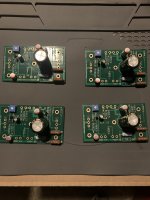
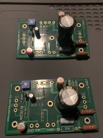
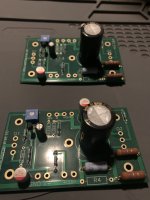
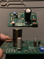
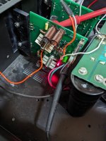
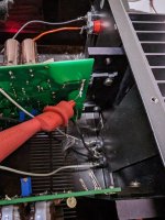
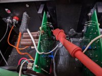
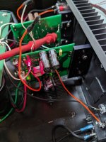
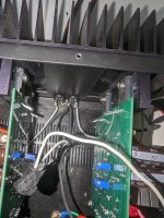
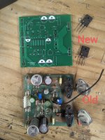
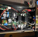
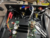
Hello all, I replaced the icepower 50asx I had in this Ghent case and am installing the Icepower 125asx module. I have it all wired up what I thought was correct and Im getting a lot of noise. Im running this single ended RCA input. I have the wiring kit for this amp from GHent audio, its their upgraded version. On the signal connector they have used a shielded cable for pins 7-8 and 6-7. Pin 8 is input 1 in 7 in ground, 6 is also ground for input 5 is input. I have used the shielding of the shielded cable for the grounds for each respective input, and the main center conductor for the positive on both. I have no idea why this is happening. Ive gone through and all the ground points show continuity to the Chassis ground. Any idea whats going on? Heres some pictures. Ive tried keeping wires away best I could from AC etc. any help greatly appreciated. Been a bad day. My TPA3255 I just built the Voltage buck converter.
Attachments
Pioneer SX-1000TA Service Manual
- By Dzrout
- Solid State
- 19 Replies
Does anybody have a service manual for this SX-1000TA?
Having an issue. It “works” tuner, phono, aux, tape. But volume is low. Looking to check Bias current.
Having an issue. It “works” tuner, phono, aux, tape. But volume is low. Looking to check Bias current.
For Sale Cerwin Vega 189SC
I have two old school perfect 189 SC for sale if anyone is interested. Driver and original box also
Bazz Fuss
- By pcardoso73
- Instruments and Amps
- 4 Replies
Hi,
Has anyone tried to build a Bazz Fuss ? I've built one yesterday but, as I didn't have the exact parts I've used what I had.
Instead of of a 2N5088 transistor I've used a 2N2222A and instead of a 1N914 diode, I've used a 1N4001.
I can't say that the sound is totally crap, but it is not very good either. It's way too dark (good for metal) and when the note is decaying and reaches low volume, it just cuts suddenly the sound (like when using a noise gate).
The dark sound should be due to the caps (I have to lower their value), but regarding the note decay could this be either the diode or transistor?
If you don't know what a Bazz Fuss is, please check here:
http://home-wrecker.com/bazz.html
Cheers,
Pedro
HELP - NOOB PLATE AMP BUILD
- By Goobernaght
- Class D
- 0 Replies
Hi fellow DIYers
I’m trying to put together a high power plate amplifier based on the ICEpower2000AS1 module.
I’m planning on a Plate Amp with
My only issue is that, I’m no engineer and can’t imagine how to even get started.
I need to source compatible modules that would add the stated functionality to my project…
I’ve done a lot of searching and the closest solution I can find is the ALLDSP 1800B but actually getting it seems downright impossible.
Can you guys suggest compatible modules that are actually acquirable, preferably plug and play…
I know my project is quite ambitious given my engineering deficiency so I’d appreciate any help y’all could offer….
I’m trying to put together a high power plate amplifier based on the ICEpower2000AS1 module.
I’m planning on a Plate Amp with
- DSP including PEQs, HPF, LPF, Phase, Sub Tuning, Auto Room EQ
- A control panel to access the DSP functions
- Dual 2000AS1 modules for a total of 4000watts
My only issue is that, I’m no engineer and can’t imagine how to even get started.
I need to source compatible modules that would add the stated functionality to my project…
I’ve done a lot of searching and the closest solution I can find is the ALLDSP 1800B but actually getting it seems downright impossible.
Can you guys suggest compatible modules that are actually acquirable, preferably plug and play…
I know my project is quite ambitious given my engineering deficiency so I’d appreciate any help y’all could offer….
For Sale Crossover parts: Duelund, Path Audio, Mundorf
- By Geluidloopt
- Swap Meet
- 14 Replies
Selling the following:
Will take offers for multiple items
2x Duelund CAST Loudspeaker Cu 12uF :SOLD
2x Duelund CAST Loudspeaker Cu 1uF : SOLD
2x Duelund CAST PP 20uF : 80€/pair
2x Duelund CAST Inductor 12AWG 2.2mH:400€/pair
2x Mundorf CFC14 coil :SOLD
Duelund Cast silver/graphite resistor 10W: 12€/pair
2x 2R4 SOLD
2x 6R0 SOLD
2x 9R1 SOLD
PathAudio resistor 10W: 10€/pair
2x 3R3 SOLD
2x 6R0 SOLD
2x 9R1 SOLD
2x 12R SOLD
2x 18R SOLD
2x 50R SOLD
2x 68R SOLD
Items are in Belgium, will ship worldwide
Attachments


Simplest Ian Canada setup
Hi, stumbled upon this forum when searching for a new dac hat for pi. Maybe I am in the wrong place but am only looking for a rough opinion so I know if investigating further is worth it.
Was initially looking for an Allo Boss but found this gear from Ian Canada that looks promising. Somewhat hard to know exactly what I need to build the first and simplest version of a dac with this. Would the enclosed 3 parts (and pi) be enough to have it functioning in a good way? Like the fact that it could be upgraded further on.
And second, and most important, would this be a "substantial" sound improvement over the Allo Boss if using average hifi gear (Hegel H80/Q Acou. 3020i)?
Need recommendations on lower power chip amps
- By gabripeic
- Solid State
- 36 Replies
Hi everyone.
I just finished making some speakers using markaudio chn-50 drivers, And now i am looking into either buying or building a small amp.
If i go with diy route what would be some decent 10-15w chip to base this amp on ?
I want something decent sounding and preferably powered by a single supply, But i can work with dual rail if necessary.
I was thinking of using lm1875, But the drawback is that it can't work with single rail.
Also i would need some decent dc protection circuit since i am not comfortable without one.
I just had my tda7294 amplifier blow up from esd discharge, When it blew up it let dc into one of the speakers. Luckily i turned it off immediately.
FS 10 x MAT-02FH (AD) & 6 x MAT-03FH (PMI) low noise
I have 10 pieces MAT-02FH (used) & 6 pieces MAT-03FH new, both are BJT DUAL transistors, and for sale. They are very low noise transistors from Analog Devices and PMI. For one (1) MAT-02 I would like 12 €, and for one (1) MAT-03 15 €.Price is excluding shipping and PayPal fee. Preference and priority is given to buyers from the EU, shipping outside the EU is possible, take a bit more time.
Attachments
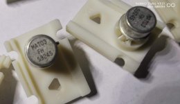
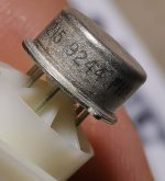
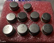
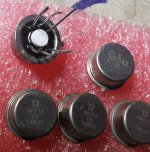
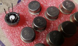
Orion XTR2500.2 DC at Spk terminals
Good day folks,
Been pulling my hair out with this one. Amplifier came in, in protect. No shorts found, powered up and confirmed unit going into protect.
Noticed brief DC at the L-ch Spk terminal. Disabled the protection and powered up, unit powered up ok, good rails and regulated LV supplies. L-ch measures +62vdc across the speaker terminals. Inserted audio and r-ch passed clean audio.
Began troubleshooting and didn’t find any defective components in circuit for the L-ch. pulled both pre drivers B631k/D600 out of circuit and these tested ok. Replaced with new and DC went away.
Unit passed clean audio, reassembled and loaded unit, around 65deg C, unit went into protect. When checked, DC at L-ch Spk terminals again.
Continued troubleshooting, this time replaced all components from the differential pairs to the pre drivers, unit still has DC at L-ch Spk terminals.
I’ve been using the schematic attached in the below thread, this seems to be most accurate.
Anyone got a remedy for all components testing ok and DC at the Spk terminals?
https://www.diyaudio.com/community/threads/orion-xtr-2000-2-output-transistors.382338/
Attachments
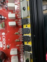
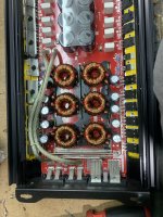

Skar SKV2 2500.1D
Hi everyone. I'm new to the forum and I think I posted this in the wrong section the first time. I have a skar skv2 2500.1d that blew a few caps. I replaced the caps and the power supply seems to be back working. The output section I not working correctly. I'm not getting switching I think it's called or square wave. I was gonna try replacing the chips on the driver card but they were scraped off. Could someone identify these parts for me please! Thanks


Noise problem that goes away at max volume
- By anhhct
- Solid State
- 26 Replies
Newbie question.
I'm wiring up a dual mono blocks amplifier (this board: https://www.aliexpress.com/item/1005003450663314.html) , here's what i have so far (pardon the ugly drawing):

Plugging it in without RCA input, there's hum.
Plug RCA input in, hum is reduced. It goes up when the volume stepped attenuator is turned up, but gone completely when attenuator is at 10. Reduce it to 9 and hum is back immediately.
Can someone explain why there's no noise when the volume knob is at maximum?
I've done some internet search, somewhere says it is with grounding but no details explaination.
My country uses 2-prong electric system so i don't have any earthing. All connections are depicted in the image.
Looking forward to your suggestion.
Thanks.
I'm wiring up a dual mono blocks amplifier (this board: https://www.aliexpress.com/item/1005003450663314.html) , here's what i have so far (pardon the ugly drawing):
Plugging it in without RCA input, there's hum.
Plug RCA input in, hum is reduced. It goes up when the volume stepped attenuator is turned up, but gone completely when attenuator is at 10. Reduce it to 9 and hum is back immediately.
Can someone explain why there's no noise when the volume knob is at maximum?
I've done some internet search, somewhere says it is with grounding but no details explaination.
My country uses 2-prong electric system so i don't have any earthing. All connections are depicted in the image.
Looking forward to your suggestion.
Thanks.
Attachments
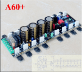
5 band tone control
- By ToFa
- Analog Line Level
- 35 Replies
Hi
I have been looking for a 5 band tone control on the internet. I found some circuit diagrams on pinterest. I don't know much about how tone controllers work but I want to DIY one for my amp. Building stuff by myself is fun. I am interested in OP Amp based preamps because getting specific transistor is hard. Here's some circuit diagrams I have found. I am interested in active tone controls(which I don't understand much but seems more interesting). If these circuits are no good please provide me one circuit that is tested and performs great.
Thank you.
Attachments
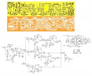
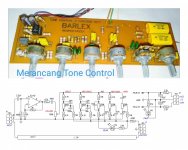
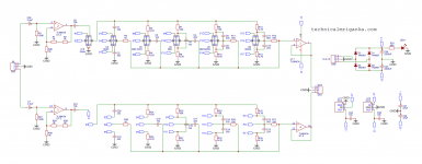
Sound Solutions Audio 2-Way Passive Audio design
I haven't been on this site for a few years, Car audio has taken a back burner.
A good fried of mine, Aaron Clinton, asked me to design a crossover for his 6 1/2" woofer and 1 1/18" silk dome tweeter. I designed what I believed to be a non-cost compromise design, it turned out pretty good. The production version omitted some of the additional Polypropylene bypass capacitors and the zobel, but the filter design is the same. He will be releasing the full schematic and parts list soon, as well as the option to buy just the PC boards. Anyway, it was a fun project and turned out quite well in my opinion,. Here are few pictures and the released preliminary white paper.
As aside note, the production car audio versions are bi-amp capable, the PC boards for DIY only have single inputs for now. The DIY versions in the pictures are the car versions, we also completed some of the home audio versions with the tweeter eq included.
-Mike
Attachments

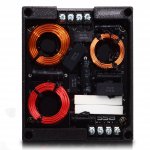
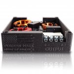
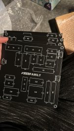
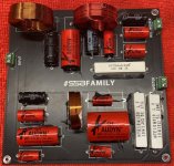
Making easy DIY "Depot" sound Diffuser panels, step by step
- By bwaslo
- Room Acoustics & Mods
- 236 Replies
I posted about these on the Multi-way forum, but then thought this might be a better place. And since I'm currently obsessed with diffusers and was recently making a new tall pair, I took photos during the assembly process to make a little article to show how easy they can be to build. These can be a nice one-day project and would almost certainly make more of a change to a system’s sound than changes to electronics or wiring, maybe even than speakers.
 Diffusers are a less often used, usually too-expensive type of room treatment. Absorbers are the more common type. Absorbers remove energy from sound waves that hit them, effectively smoothing responses and reducing specular reflections, and are usually the first choice. But after a point too much absorption starts to make the room seem dead or even downright uncomfortable to sit in. Diffusers break up specular reflections but don't absorb the energy. Instead, energy at different frequencies is scattered over a wide area and range of time delays. Diffusers don't kill the lively-ness of a room but can make it sound much richer and seemingly larger. Placed at reflection points or behind the listening chair, they make a dramatic and immediate effect, not one of those "I think I can hear it" kind of things.
These ultra-easy, wideband, inexpensive diffusers perform well from about 400Hz to 8kHz. They are 1D "step” type diffusers, optimized using the diffusion simulator “AFMG Reflex”. They simulate well, even compared to the usual QRD diffusers you might be familiar with. Credit for the assembly concept and instruction on optimizing step diffusers goes to Tim Perry at Arqen Sonic.
 This design size is ~34.5" wide, and up to 96" tall (or roughly 3'x8'). Making them 96" tall is probably the easiest height choice since it uses most of the lumber in as-bought dimensions and avoids the majority of wood cutting. The thickness of the assembly is about 4.5 inches. The wood, other than a few plywood base pieces, is inexpensive spruce/pine/fir "furring strips", commonly available in US. Needed tools can be as little as a hammer and nails and a pencil, if you can get your lumber store (or big box store) to do some simple cuts of the wood pieces for you. Assembly time is on the order of an hour or two for a basic diffuser, using a #18 1” brad gun (which made it really easy), longer if using only a hammer and nails.
The total cost of wood for one 8ft tall diffuser should be around $92 for one 8ft diffuser, with left over plywood. Two would cost about $152, three would be about $212.
WAF might be a factor choosing to install these, but I think if they were near floor-to-ceiling sized and painted to match the wall colors they could look pretty nice, or at least inoffensive. I like the way they look, even without any finish at all (though I'll probably sand and urethane them sometime).
The first step is to get the wood, enough to build the height you want to make. Try to pick mostly un-warped, decent looking pieces if you can. Here is what you'd need for one 8ft (96", minimum wood cutting), 34.5" wide diffuser. Alter as needed for other heights or quantities:
*Qty 4 of 96" pieces of nominal "1x2" (~0.7"x1.5" actual) furring strips, about $1 each.
Plywood, from Home Depot 577138, or Lowes 12232 , or Menards 1251061; about $32 per 48”x96” sheet (you'd need two sheets to make one diffuser, or three for two diffusers). Home Depot cut mine to these sizes at no additional cost. You need:
*Qty 2 of 12.25"x96" plywood
*Qty 1 of 34.5"x96" plywood
______________
To assemble, first lay the big piece of plywood down, ugly (unsanded) side facing up. Take one of the 1x3 pieces and set it on the plywood, aligned all the way to one (long) side. Then set one of the narrower pieces alongside the 1x3, for positioning. Move the 1x3 back and pencil mark the big piece at the four corners of the narrower ply (4 places) - also run the mark down the edge (thickness) of the big ply.
 Repeat for 4 more marks, starting this time with the 1x3 aligning piece on the other long side of the big ply.
Then, mark and draw 4 full lines the length of the large ply, spaced about half the thickness of the 1x2 wood pieces (~0.35”) away and inward from the previous marks – that is, toward the centers of where the narrow ply pieces had been positioned. The full lines indicate where to nail or drive screws to connect the 1x2 wood to the large plywood piece.
 Line up all the 1x2 pieces narrow side down and about 7 inches apart, then put the large ply piece on top of them, ugly side up. Pull one of the 1x2s over so that its end is along a short line you marked and so that the full line is about in its center. Align both ends to those lines.
 Then drive a 1” nail or brad through the ply into the 1x2, along the long line. Repeat at the other end, and about every 8 inches or so between. Repeat for all 4 boards, when done it should look like the photo above.
Move the large ply out of your way and lay down a narrow ply board “pretty side” up. Use one of the 1x3 boards to set spacing from one long edge of the ply, as before. Align another 1x3 next to it and nail that second one in place. Remove the spacing board. Align another 1x3 alongside the last one (toward the inside of the ply) and also nail it in place, then another one on top of that. Choose better looking 1x3 pieces to be the ones on top, where they will show, and use less nice ones as the covered-up pieces. Repeat with the other ply, remembering that these two ply pieces will be mirror images of each other.
 Now, lay down the large ply assembly, pretty side up and place the narrower ply pieces on top of it. Align the edges of the narrower assemblies as well as possible on top of the 1x2s of the large ply, with the 2-high stack of 1x3s toward the center, and nail the assemblies in place.
Lastly, nail a stack of three 1x3s on the narrow plywood pieces at the edges toward the center. And you’re done. That's it!

These ultra-easy, wideband, inexpensive diffusers perform well from about 400Hz to 8kHz. They are 1D "step” type diffusers, optimized using the diffusion simulator “AFMG Reflex”. They simulate well, even compared to the usual QRD diffusers you might be familiar with. Credit for the assembly concept and instruction on optimizing step diffusers goes to Tim Perry at Arqen Sonic.
The total cost of wood for one 8ft tall diffuser should be around $92 for one 8ft diffuser, with left over plywood. Two would cost about $152, three would be about $212.
WAF might be a factor choosing to install these, but I think if they were near floor-to-ceiling sized and painted to match the wall colors they could look pretty nice, or at least inoffensive. I like the way they look, even without any finish at all (though I'll probably sand and urethane them sometime).
The first step is to get the wood, enough to build the height you want to make. Try to pick mostly un-warped, decent looking pieces if you can. Here is what you'd need for one 8ft (96", minimum wood cutting), 34.5" wide diffuser. Alter as needed for other heights or quantities:
_____________ Wood List _________
*Qty 12 of 96" pieces of nominal "1x3" (~0.7"x2.4" actual) furring strips, about $2 each.Part numbers are 164704 at Home Depot, 13PFUR.8 at Lowes, 1031528 at Menards.
*Qty 4 of 96" pieces of nominal "1x2" (~0.7"x1.5" actual) furring strips, about $1 each.
Part numbers are 160954 at Home Depot, 128218 at Lowes, 1031515 at Menards.
Plywood, from Home Depot 577138, or Lowes 12232 , or Menards 1251061; about $32 per 48”x96” sheet (you'd need two sheets to make one diffuser, or three for two diffusers). Home Depot cut mine to these sizes at no additional cost. You need:
*Qty 2 of 12.25"x96" plywood
*Qty 1 of 34.5"x96" plywood
______________
To assemble, first lay the big piece of plywood down, ugly (unsanded) side facing up. Take one of the 1x3 pieces and set it on the plywood, aligned all the way to one (long) side. Then set one of the narrower pieces alongside the 1x3, for positioning. Move the 1x3 back and pencil mark the big piece at the four corners of the narrower ply (4 places) - also run the mark down the edge (thickness) of the big ply.
Then, mark and draw 4 full lines the length of the large ply, spaced about half the thickness of the 1x2 wood pieces (~0.35”) away and inward from the previous marks – that is, toward the centers of where the narrow ply pieces had been positioned. The full lines indicate where to nail or drive screws to connect the 1x2 wood to the large plywood piece.
Move the large ply out of your way and lay down a narrow ply board “pretty side” up. Use one of the 1x3 boards to set spacing from one long edge of the ply, as before. Align another 1x3 next to it and nail that second one in place. Remove the spacing board. Align another 1x3 alongside the last one (toward the inside of the ply) and also nail it in place, then another one on top of that. Choose better looking 1x3 pieces to be the ones on top, where they will show, and use less nice ones as the covered-up pieces. Repeat with the other ply, remembering that these two ply pieces will be mirror images of each other.
Lastly, nail a stack of three 1x3s on the narrow plywood pieces at the edges toward the center. And you’re done. That's it!
For Sale Rotel RKB-D8100 : 8 channels of Hypex UcD180 (100Wx8 at 8 Ohms)
- By CharlieLaub
- Swap Meet
- 1 Replies
SOLD
Location of bias shunt resistor in Tubelab SE
- By dch53
- Tubes / Valves
- 5 Replies
The tubelab SE amp design has the 10Ω bias shunt resistor in the anode circuit.

I'm using a Rod Coleman DHT regulator and looking to use a bias servo.
Just wondering why the bias shunt resistor is in the anode circuit and whether there's any problem moving it to the cathode where fixed bias resistors usually go.
I'm using a Rod Coleman DHT regulator and looking to use a bias servo.
Just wondering why the bias shunt resistor is in the anode circuit and whether there's any problem moving it to the cathode where fixed bias resistors usually go.
measure speaker impedance with oscilloscope + signal generator?
- By wall
- Equipment & Tools
- 12 Replies
Is it possible to reliably plot a speaker's impedance with a digital oscilloscope and a signal generator, and would a dual-channel oscilloscope have any advantage?
Tentlabs DHT PSU pair
For sale a used but in top condition pair of Tentlabs DHT psu for 300b,2a3 or other triodes up to 2,5A of current. Low noise psu for hiend projects. Price is 100eu incuding shipping to EU. If you will tracking and insured shipping is 10eu more. More info on contact.
Attachments
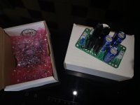
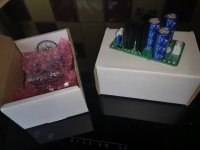
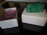
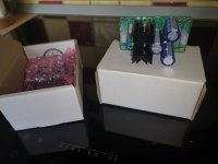
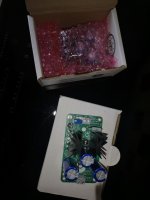
An ez DC adjustable 0dB Power DB with both Sziklai or MOSFET based on LH0033
- By mtlin12
- Solid State
- 1 Replies
I have redesigned my old 25W IRON-AMP cancelling the IPT (10dB) and make it more clean and powerful.
This easy DC adjustable 0dB Power DB with Sziklai BJT (or POWER MOSFET) is based on LH0033 as a JFET
source follower plus Power Diamond Buffer, low noise, high speed and NO output stage thermal problem.
The new amp uses cascode DN3545 + 2N5458 to replced old 2SK246 for higher voltage supply from +/-38V
to +/-70V, the bias current of SANKEN 2SC2922/2SA1216 is about 60mA and 100mA using 2SK1529/2SJ200.
With a good pre-amp followed by this unity-gain power DB will make it a very good non-global-NFB amp!🙂
Attachments
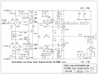
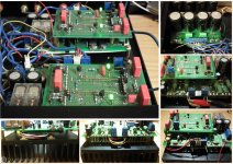
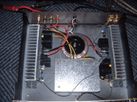
Speaker capacitor upgrade advice
- By Mikeinstereo
- Multi-Way
- 13 Replies
Hi
I have two-way speakers, which are nearly 25 years old but in excellent condition. However, there are a mix of electrolytic as well as polypropylene capacitors on both the tweeter and bass sections on the cross over which have never been changed.
The question is; do I change just the one electrolytic capacitor for polypropylene in the tweeter section and leave the other polypropylene caps alone? Or, change all the electrolytics out on both tweeter and bass section for polypropylene? Alternatively, change all caps, both electrolytic and polypropylene for new polypropylene so all caps are the same age and quality?
DC Blocker (mains) for high power amp
- Power Supplies
- 57 Replies
I've been asked by a friend to make him a DC blocker for his Krell monoblocs - a pair of brutes with a maximum power consumption of 6kW, and for which they recommend a dedicated 20A spur!
Having perused the many, oft-conflicting threads, I'd like to use a simple blocker circuit with large elctrolytic caps and antiparallel diodes as per the much-discussed Bryston circuit, but using much larger caps (up from Bryston's 0.33mF/6.3V to 1.0mF/16V).
These are rated for a maximum ripple current of 14 Amps, and it is my intention to use a pair in parallel to give >20 Amps headroom, plus a similarly robust bridge rectifier.
If I've understood it correctly Bryston use their caps in parallel assuming no significant reverse voltages (<1V) will be encountered; while Rod Elliott and others use caps in back-to-back series to protect against any reverse voltage scenarios.
The disadvantage of the latter approach is that you need 4 x the capacitance to achieve the same ripple current handling, which becomes hopelessly expensive and outsized in the case I'm trying to get my head around.
So, would it be possible to protect the caps from reverse voltage by using a suitable diode after the blocker to drop reverse voltage above a certain threshold to Earth - since it shouldn't be present unless a fault state exists? If so, which kind (transil, avalanche, single high power rectifier?).
I want to create a safe and extremely robust solution, but don't have the skills to model this, nor the test equipment to do more than PAT type safety stuff. I'm aware of the need to properly rate, fuse, insulate and earth every last aspect.
Many thanks for any input.
Having perused the many, oft-conflicting threads, I'd like to use a simple blocker circuit with large elctrolytic caps and antiparallel diodes as per the much-discussed Bryston circuit, but using much larger caps (up from Bryston's 0.33mF/6.3V to 1.0mF/16V).
An externally hosted image should be here but it was not working when we last tested it.
These are rated for a maximum ripple current of 14 Amps, and it is my intention to use a pair in parallel to give >20 Amps headroom, plus a similarly robust bridge rectifier.
If I've understood it correctly Bryston use their caps in parallel assuming no significant reverse voltages (<1V) will be encountered; while Rod Elliott and others use caps in back-to-back series to protect against any reverse voltage scenarios.
The disadvantage of the latter approach is that you need 4 x the capacitance to achieve the same ripple current handling, which becomes hopelessly expensive and outsized in the case I'm trying to get my head around.
So, would it be possible to protect the caps from reverse voltage by using a suitable diode after the blocker to drop reverse voltage above a certain threshold to Earth - since it shouldn't be present unless a fault state exists? If so, which kind (transil, avalanche, single high power rectifier?).
I want to create a safe and extremely robust solution, but don't have the skills to model this, nor the test equipment to do more than PAT type safety stuff. I'm aware of the need to properly rate, fuse, insulate and earth every last aspect.
Many thanks for any input.
Filament voltage 12AT7 / 12AU7
- By AudioFanMan
- Tubes / Valves
- 29 Replies
I see the maximum filament voltage for the 12AT7 is 6.3 and the 12AU7 is 6.6
and as it goes my virtual center tapped ps is at 6.9
Should I leave it, or should I try to knock .5v or so off ?
If I wanted to work on a small reduction I was thinking there are two ways,
The virtual center tap config looks to be the standard 100 ohm resistor off each leg to ground.
At the sacrifice of more current through that 6.3 coil I could reduce the 100 ohm resistors a little
or
may be add a resistor in series with the heaters...
My gut kick is to add something in series...
Thoughts?
EDIT:
12AU7EH shows 6.6 (Electro-Harmonix)
Correcting my post now, after euro21 caught my error
Tricks using a smaller enclosure 12" woofer
- By wickette
- Construction Tips
- 55 Replies
Forgive the long rambling nature of this post...
The TLDR version; is a 7/8" deep port in a 5/8" thick enclosure wall really aperiodic or ported?
-If its the former, how much of an affect will 25% less volume really have
-if its the later, how much airflow can an odd shape enclosure be choked without affecting response (ie bottom picture)
I'm forging ahead fitting a 3 way cabinet speaker into a shelving unit I made.
Its an old 1990 model. Internal volume is 2.1³ ft. The tweeter MW are encased from behind in and have a high XO, all that volume is used by the 12" woofer (which runs full range).
It's spec'ed as ported, frequency response 45hz-20khz but the port is 1.8" diameter, 0.9" deep (very slightly thicker than the wood).
The shelving unit can fit 1.35³ ft enclosures. Stuffing fiberglass in theory makes the relative size 75% of the original size. Without t/s parameters or modeling is there any predictions on how the reposnse would chance?

If I lose some of the bass extension but the response above 110hz is mostly unchanged I can live with that. (I think that has more to do if the original really is a ported enclosure or aperiodic.
With that said, I can increase the volume using odd size extensions to the enclosure, but I think my ideas would create more problems even if the total volume is identical, right?

The TLDR version; is a 7/8" deep port in a 5/8" thick enclosure wall really aperiodic or ported?
-If its the former, how much of an affect will 25% less volume really have
-if its the later, how much airflow can an odd shape enclosure be choked without affecting response (ie bottom picture)
I'm forging ahead fitting a 3 way cabinet speaker into a shelving unit I made.
Its an old 1990 model. Internal volume is 2.1³ ft. The tweeter MW are encased from behind in and have a high XO, all that volume is used by the 12" woofer (which runs full range).
It's spec'ed as ported, frequency response 45hz-20khz but the port is 1.8" diameter, 0.9" deep (very slightly thicker than the wood).
The shelving unit can fit 1.35³ ft enclosures. Stuffing fiberglass in theory makes the relative size 75% of the original size. Without t/s parameters or modeling is there any predictions on how the reposnse would chance?
If I lose some of the bass extension but the response above 110hz is mostly unchanged I can live with that. (I think that has more to do if the original really is a ported enclosure or aperiodic.
With that said, I can increase the volume using odd size extensions to the enclosure, but I think my ideas would create more problems even if the total volume is identical, right?
Error correction for Single Ended transistor amplifier - is it possible?
- By gentlevoice
- Solid State
- 11 Replies
Hi All,
For some time now an acquaintance of mine has been using a single-ended class A amplifier - with much satisfaction as I understand him - although this amplifier topology has a rather steep distortion increase when playing loud(er). With this in mind he has asked me if something could be done to amend this high distortion level while maintaining the sound qualities that he finds this amplifier topology to have.
FYI I have attached a schematic of the amplifier circuitry as it overall looks today.
I have been considering something like boot strapping or a Sziklai output stage (right side schematic drawing), however, I wonder if there could be some kind of "error correction topology" (i.e. not global feedback) that would work for single-ended circuitries (and still sound excellent)?
In my thinking the main issue is the output stage where the distortion gets quite high even at moderate playback levels (please note here that I am aware that CCS'es could be substituted for the resistors R1, R2, R9 and thus improve distortion figures. In this context I would hope to find some "single ended error correction topology").
Might one/some of you have some insight into this that you could share?
Cheers & thanks for your inputs,
Jesper
Attachments

just curious about a MJ class A amp circuit?
- By epkoncept
- Solid State
- 14 Replies
hi:
about +20 years ago there was a series of construction articles in a Japanese magazine "MJ" for a No negative feedback Class A power amp ( both BJT and MOSFET).
No voltage gain, just a huge current buffer.
I built the BJT one. I have the construction article somewhere.
I was curious if anyone else has built one or would be willing to comment on the design if I posted the circuits ?
Also there was a No NFB class A pre-amp using a single power JFET. Similar request.
P
Be aware -- new rules for shipping to the EU via US Postal Service
These regulations went into effect on March 1, 2023.
You may be as surprised as the Postal Clerk was this afternoon. Shipping to the EU from the US used to entail a Form 2976. Now you fill out the Form 2976 AND the clerk types in the data regarding quantity, weight and type of object. This generates a USPS shipping label. You can now generate the 2976 if you have an account with the US Postal Service.
It also generates a bill for the recipient to pay duty or tariff on the shipment.
Applying basic room correction via DSP
- By soltung
- Full Range
- 3 Replies
Eventually I will be building 2 or 3-way OBs and want to use a MiniDSP 2x4 as the "conductor."
My question is: I'd like to learn how to use the MiniDSP 2x4 now by applying some basic correction to a system that consists of:
1 pair of full range OB speakers + SET tube amp + subwoofer.
What are the straight forward corrections that makes sense to experiment with? I have NO experience with DSP at all.....The basic nugget I've learned thus far is that DSP correction below <200hz is where it's most useful. Hoping someone can drops some knowledge, since I know nothing about this, and def want to learn.
-
Poll
Is your system silent?
- By EdGr
- Solid State
- 55 Replies
Here is the test:
My system is silent. This is my integrated amplifier with regulated supplies for all but the output stage, and transformers located far from the input.
I am curious how many systems can pass the test.
Ed
- Set the input selector to an unused input (open-circuit)
- Turn the volume control to maximum
- Place your ear next to the speaker (if needed!)
My system is silent. This is my integrated amplifier with regulated supplies for all but the output stage, and transformers located far from the input.
I am curious how many systems can pass the test.
Ed
Help with Marantz 2216B caps replace old polar with non-polar caps?
A friend bought a Marantz 2216B amp, i am helping him bring it back to life. The tuner section works fine, so there is hope.
I am looking at the schematic for the phono amp here:

As i read it C415/16 are the input caps, 1uF @ 50V polar electrolytic.
Can they be replaced by a non-polar cap? The same would apply, i think, to C401/02.
I am curious if this was a design decision, or a design restraint due to capacitor technology and cost at the time.
I am looking at the schematic for the phono amp here:
As i read it C415/16 are the input caps, 1uF @ 50V polar electrolytic.
Can they be replaced by a non-polar cap? The same would apply, i think, to C401/02.
I am curious if this was a design decision, or a design restraint due to capacitor technology and cost at the time.
Attachments
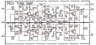
EQ APO commands feedback
- By DIYhopeful
- PC Based
- 3 Replies
Hi there,
I'm pretty bad with code and commands etc. so I would like some feedback for my commands. I've got an AVR using 6 channels to 6 drivers (TMW) for a 3 way active stereo setup. The Sub is on the pre-out. No center channel.
The code has to downmix multi channel content first (if it is multichannel 5.1 or 7.1) and then has to upmix it into my 6 "channels". Or just straight up upmix it if it is only stereo content.
I would prefer if I could upmix into the subwoofer channel as well so that I can independently adjust volume, EQ and create steeper crossovers for it in the signal chain. I tried the command "copy SUB: 0.5*L+0.5*R" but it didn't work . The crossover that the AVR has for it is not to my liking. (Also I wonder how the AVR mixes the sub channel for content that does not have a ".1" channel in the signal).
Some were generated by the PEACE GUI and it never sounded right. Eventually figured out the Upmix button in the GUI generated the following command was much worse than my version of the command which I modified the original and it sounds way better. The imaging was utter garbage before. 2 of my drivers "L" and "R" were playing in mono. Some test tracks revealed that to me immediately.
The original:
This is the downmix section if I'm correct
also if you look closely here the Left channel has rear right and surround right copied into it. Same goes for the Right channel. Code is bad maybe? and what's up with the random numbers like 0.222 and 0.157 etc.
Copy: L=0.222*L+0.157*C+0.022*SUB+0.189*RL+0.116*RR+0.203*SL+0.090*SR
Copy: R=0.222*R+0.157*C+0.022*SUB+0.189*RR+0.116*RL+0.203*SR+0.090*SL
and this is the upmix section. what is MUP?
Copy: MUP=0.5*L+0.5*R
Copy: SUB=MUP
Copy: RL=L
Copy: RR=R
Copy: SL=L
Copy: SR=R
My version:
Copy: L=1*L+1*C+1*SUB+1*RL+1*SL
Copy: R=1*R+1*C+1*SUB+1*RR+1*SR
Copy: RL=L
Copy: RR=R
Copy: SL=L
Copy: SR=R
So yeah, I'm not sure what I did exactly and what "MUP" is and why it is at 0.5x signal for the LR channels, but I'm looking for feedback if I'm wrong or if I can optimize it further like what is the correct way to upmix into a multichannel active speaker setup. I tried messing with it but something bad happened and the sub channel went up to max signal for some reason and it made a huge pop before anti-clipping kicked in. Fortunately nothing blew up.
Any assistance will be greatly appreciated! And it would be even more appreciated if you could direct me to a comprehensive reading material on how to use this software.
6Bryston mono block repair
- By MrBrian
- Solid State
- 3 Replies
Anybody have any experience repairing a Bryston 6B monoblock power amp? I can't find a schematic but I found a 7B and a stereo 6B but I heard the 7B would be closer to the 6B mono, the unit I have and am wanting to repair, if it's not too crazy a hassle to do. Any help would be much appreciated.
I'm almost certain there are multiple blown power transistors, aside from locating and replacing failed transistors, what else should I expect to replace or what else should I look for? I apologize my question is vague, any help would be very much appreciated
Thank you so much, Brian S.
I'm almost certain there are multiple blown power transistors, aside from locating and replacing failed transistors, what else should I expect to replace or what else should I look for? I apologize my question is vague, any help would be very much appreciated
Thank you so much, Brian S.
Unexplained level of distortion in parallel 300B SE output stage
- By dch53
- Tubes / Valves
- 42 Replies
I’m repairing 4 parallel 300B SE amps. 2 hummed and all had very poor implementations of bus earthing.
Here’s the schematic

3 of the 4 amps measure well into 8Ω with 1kHz 1W THD around 0.5% at 1W.
The remaining one has distortion that is 5x worse at 2.5%.

The distortion profile at the SRPP output and the grids of the 300Bs is exactly the same as that in the other 4 amps which suggests the problem is something to do with the output stage.
Swapping 300Bs, SRPP tube, driver tube and rectifier tubes all have no impact on the distortion measurement.
Just to be sure that the OPT was setup for 8Ω I measured the voltage ratio: 14 for a primary impedance of 1580Ω with an 8Ω load. OK for parallel 300Bs.
Are there any potential sources of output stage distortion I’m missing here please?
Here’s the schematic
3 of the 4 amps measure well into 8Ω with 1kHz 1W THD around 0.5% at 1W.
The remaining one has distortion that is 5x worse at 2.5%.
The distortion profile at the SRPP output and the grids of the 300Bs is exactly the same as that in the other 4 amps which suggests the problem is something to do with the output stage.
Swapping 300Bs, SRPP tube, driver tube and rectifier tubes all have no impact on the distortion measurement.
Just to be sure that the OPT was setup for 8Ω I measured the voltage ratio: 14 for a primary impedance of 1580Ω with an 8Ω load. OK for parallel 300Bs.
Are there any potential sources of output stage distortion I’m missing here please?
Alembic F-2B transformer for balanced audio output
- By ClydeWilliam
- Tubes / Valves
- 1 Replies
Hi,
I have a pretty early Alembic F-2B preamp, which is fantastic.
In the past, I've run it's output into an off-the-shelf DI box for recording, or in between a power amp
I'l like to build a dedicated DI box for it, with a transformer that has an optimal input impedance. I am curious to see if any difference would be noticeable.
Alembic's datasheet states an output impedance of 91K
http://www.alembic.com/support/F2B_manual.pdf
Would anyone have a transformer recommendation that would best suit this application (91KΩ to 600Ω)?
Or, is this a total waste of time, and i should just stick with what I've got? (Whirlwind, with what i believe is 1MΩ input impedance)
Thanks in advance.
Toroidal Buzz - Reset by Power Cycle?
- By RickySnit
- Solid State
- 30 Replies
Hi Gents, I had an interesting occurrence I was curious if anyone had some insight to. I have a Classe DR-8, I've recapped it, new signal wire, generally left the power section alone. It's been great for weeks continually on - all of a sudden the transformer started humming fairly loudly. I shut the amp off, noticed the power fuse blown - replace the fuse with a 6A (from 8, it's what I had), turned it back on - all fine.
Very interesting, would this be a symptom of a Toroidal on it's way out? Or symptom indicative of something else?
Would enjoy the thoughts! Thanks..
Very interesting, would this be a symptom of a Toroidal on it's way out? Or symptom indicative of something else?
Would enjoy the thoughts! Thanks..
Load more
Projects by fanatics, for fanatics
Get answers and advice for everyone wanting to learn the art of audio.
Join the Community
507,634
Members
7,881,317
Messages