You are using an out of date browser. It may not display this or other websites correctly.
You should upgrade or use an alternative browser.
You should upgrade or use an alternative browser.
Filters
Show only:
How to lower the internal volume of an already finished eclosure
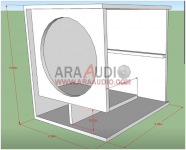
the story in brief: I have a pair of speakers that I call "Satori Frankestein" with SB satori MW16p-8 + SB satori TW29R, the cabinet is that of Jeff Bagby's Kairos but I'm testing the crossover of Joachim G's Kalasan 5. Having difficulty to obtain a smooth low end, I want to experiment with a lower volume of the cabinet, however since it does not have openable sides and that the internal surfaces are covered with felt, the operation is not so simple and reversible, I thought I would try it by inserting some volumes of polystyrene between the sides of the cabinet (equivalent to about 3 liters) but I wonder if the polystyrene is dense enough for this purpose and also if fixing it only by interlock could have a bad influence on the result
Jim Thompson
- By rayfutrell
- In Memoriam
- 1 Replies
Does anybody know if Jim Thompson died? He had the analog-innovations website. I heard he was sick in 2018 and he vanished, but I never saw an obituary.
Solid State Replacement for CV378/GZ37
- By richard8976
- Power Supplies
- 1 Replies
Hi. I want to "release" three CV378 rectifier tubes in a radio transmitter I have by replacing them with solid state rectifiers (preferably within an octal plug). Can anybody point me to such a replacement or offer and insight as to what I might be looking for? When I've sourced a replacement I can then offer them for sale as used. I've got a good valve tester so I can vouch for their condition. Thanks. Rich
EDIT: I see products for GZ34 but not GZ37. Quite possibly I might need to create a homebrew solution, not sure.
EDIT: I see products for GZ34 but not GZ37. Quite possibly I might need to create a homebrew solution, not sure.
FS: Fostex T-845
I have a pair of Fostex T-845 for sale. Both work fine, but one terminal broke off - see photo - and I don't know how to reattach it to the body. Make me a reasonable offer.


Bluetooth Headphone Amplifier Project
- By Alchamist
- Headphone Systems
- 4 Replies
As you know we have great headphone amplifier projects like KORG Nutube B1, Noir HPA, Whammy HPA etc. Is it possible to make similar quality one wireless (Bluetooth) headphone amplifier project on a commercial headphone? Is it possible to make a product better than the Apple Airpods Max? Or do you know already made one ? Could you share?
Best Regards
Best Regards
Wondom Jab5 vs Zoudio
- Chip Amps
- 13 Replies
Hey guys, I'm looking for another amp/dsp setup for my next build. I want to do a pair of 2 way active bookshelves with a Subwoofer.
What is better ??? Is there anything else out there that is 4 channel WITH dsp?
What is better ??? Is there anything else out there that is 4 channel WITH dsp?
ModSquad Prism CD player external power supply
- By Nfids73
- Digital Source
- 4 Replies
Hi I have a question for this group of fellow enthusiasts. I have a ModSquad Prism player, the Magnavox CDB-650 version, and I somehow have lost the external power supply. Was wondering if anyone could please help me with the voltage/amperage and wiring pinout for the mini XLR connection? It’s driving me crazy not knowing where it went and I figured I’d just build my own or find one compatible.
Any assistance would be very greatly appreciated.
Thanks
Any assistance would be very greatly appreciated.
Thanks
NE5532P how to change output frequency
- Chip Amps
- 10 Replies
Hi! also with my problem with edifier s730, based on 4x TDA7294 and 6xNE5532
my problem is that i want to change output frequency for my satelits, now is cutted to aprox.=150hz, i want it on 80-100hz to get more bass, i changed speakers for satelits but i need them to get i little bit lower
can someone help me? what capacitor i need to change?
link to NE5532 datasheet https://www.alldatasheet.com/datasheet-pdf/pdf/17968/PHILIPS/NE5532.html
TDA7294 https://www.alldatasheet.com/datasheet-pdf/pdf/25103/STMICROELECTRONICS/TDA7294.html
Attachments
Search: "Studio Speaker" ala SCM150A / KH420 with Bliesma + Motional feedback
- By Spliffgroen
- Multi-Way
- 1 Replies
Hello All,
This is my first post. Im following and reading the forum for a couple of months.
Im thinking about doing a speaker ala SCM150A or KH420 with the new
Bliesma mid dome and tweeter (since they spec rather impressive).
1) I know there where SCM150A clones in the past.. is any one working on
a similar project besides the "coffin box"?
2) The KH420 has waveguides. Since is more of a studio use im more interested in
"just" front then wide dispersion. Any thought on this?
3) I heard a 3-Way from Philips with motional feedback, the same speaker with the motional feedback bypassed made a huge
difference in distortion, so for the woofer it would be rather nice i guess. I've also heard the Grimm audio since I was interested in
the bliesma.. but rather prefer a soft mid dome as in the Philips but.. slightly tighter and modern.
4) If find the SCM150A and PSI A25M low end quite nice any thoughts on a woofer like this?
5) I don't want it to sound the same.. but I think choosing the bliesma tweeter and dome "" woofer can get
me (with hard work) in the same kinda ballpark. So any refreshing thought or similar project are welcome!
Thanks.
Counterpoint SA12, A journey
- By konst
- Solid State
- 18 Replies
Disclaimer: this is a bit of a journey, do not try this at home, the HT on these amps stings like a wasp, your life is in danger and may end if you are not careful or don't know what you are doing.
I have a SA12 that I purchased of Ebay for about 150bux with both channels dead. I thought this might make a great project case for something or other I will think of in the future.
It arrived and quite a few components were blown including 3 of the 8 output devices. Capacitors were leaking although in spec, but the filtering caps and transformer are in good shape, even for 30years old.
After much discussion with Anatech (a mind of useful knowledge), and Grimberg (same mind of great knowledge), I came to the conclusion that successful ownership of an SA12 is down to the skill and willingness of the owner to experiment and take it wherever it may go due to unobtainium of some parts.
With this in mind, I set out and decided that the plan of action was as follows:
1- Recap (all but PSU)
2- Replace all semi's, as they are getting on in age, and not expensive to replace
3- Test various output MOSFETS to see what works.
Please note that I do not technically have the skillset for this whatsoever. I have been soldering and fixing small things since I was 9, but this is a bigger undertaking and would require significant research into how MOSFETS worked in general and what would be required to incorporate them into this design.
Sigma Studio sidechain?
- By Hayden
- Software Tools
- 5 Replies
Anyone know Sigma Studio simple programming and can help a brother out?
The programming is nearly done except one thing low pass volume, I must be missing something.
Any help would be unbelievably appreciated 🙂
The programming is nearly done except one thing low pass volume, I must be missing something.
Any help would be unbelievably appreciated 🙂
TDA72XX related question. On overshoot and ringing.
So I spent a few weeks trying to see if anybody has encountered opamp over shoot and ringing on the TDA72XX series.
The design is as per the data sheet. Overshoot and ringing was observed on various TDA PCBs.
So after weeks of searching I could not find a single bit of info that somebody has been able to achieve this.
I did find a few posts on here where others said they are facing the same problem. These guys have purchased all their parts from reputed companies so that eliminates my doubt about my TDAs not being original.
I have tested all my TDAs. To see if the power output is at least ok and meets the specs of the orignal IC and they do.
If anybody has been able to build a TDAXX and get a clean signal without over shoot and ringing.
It would be nice to see a pic of the scope screen as well as how you achieved this.
Before I throw in the towel on these efforts and move to building and testing PCBs for the LM3886 I though Id make this one last ditch attempt to figure this out. Any inputs appreciated.
My test setup. TDA7294. Square wave pulse sent into the input pin from my phone or function generator or pc I tested all 3. Scope sitting on the output pin. (Tested both with and without speaker load of 8 Ohm speaker.
Threshold NS10 schematic - Is this the original N.P. version?
Threshold NS10 schematic - Is this the original


Hi all
- By zywalek
- Introductions
- 2 Replies
Hi,
I am new here. I am glad I can join the DIY family!
Cheers
I am new here. I am glad I can join the DIY family!
Cheers
A tale of 12" subwoofers, distortion and 15 dollars.
- By shrub0
- Subwoofers
- 341 Replies
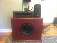
In July I picked up a dayton audio RS1202A Dual subwoofer on the used market. I was very excited about this purchase it uses two 12" dayton reference series subwoofers in 2.1 cu ft (60 liter) of airspace with a SPA1000 plate amplifier.
However, I did not really like the sound of this setup. I'm not sure if the suspension is too stiff or the inductance or moving mass is too high but it seems to miss the peak spl of a kick drum hit and can't keep up with quick notes on a bass guitar. I know there is a lot of opinions of subwoofer transient response and I don't really want to get into that discussion, but I am running these up to 100hz so I am possibly getting into territory where the ear is more sensitive to transient response.
I then decided to take distortion measurements and try different 12" subs in the box.
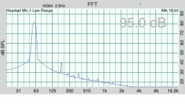
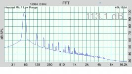
For distortion measurements I used a IMM-6 mic and constant sine waves. I then turned up the gain until a harmonic was -25db down an approximation of 5% distortion. I did these in room at 4 feet away. I realize that in room measurements are not as meaningful as ground plane but since I keep the sub box in the same position in the room after changing drivers I feel that my measurements have some value. My microphone starts to clip around 115 db so I am not always able to get a 63hz result at full volume
Below is the measurements of the original setup:
frequency Spl of fundamental 2nd harmonic 3rd harmonic
16 92 -39 -28
20 89 -37 -27
25 98 -26 -22
31.5 100 -23 -26
40 90 -18 -25
50 107 -25 -30
63 112 -30 -40
I've attached photos of the setup and the spectrum of 60hz at 80db and 100db.
However, I did not really like the sound of this setup. I'm not sure if the suspension is too stiff or the inductance or moving mass is too high but it seems to miss the peak spl of a kick drum hit and can't keep up with quick notes on a bass guitar. I know there is a lot of opinions of subwoofer transient response and I don't really want to get into that discussion, but I am running these up to 100hz so I am possibly getting into territory where the ear is more sensitive to transient response.
I then decided to take distortion measurements and try different 12" subs in the box.
For distortion measurements I used a IMM-6 mic and constant sine waves. I then turned up the gain until a harmonic was -25db down an approximation of 5% distortion. I did these in room at 4 feet away. I realize that in room measurements are not as meaningful as ground plane but since I keep the sub box in the same position in the room after changing drivers I feel that my measurements have some value. My microphone starts to clip around 115 db so I am not always able to get a 63hz result at full volume
Below is the measurements of the original setup:
frequency Spl of fundamental 2nd harmonic 3rd harmonic
16 92 -39 -28
20 89 -37 -27
25 98 -26 -22
31.5 100 -23 -26
40 90 -18 -25
50 107 -25 -30
63 112 -30 -40
I've attached photos of the setup and the spectrum of 60hz at 80db and 100db.
Attachments
BPA-200 w/ six chips working w/ pics!
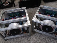
Well, my bpa-200 is working. I haven't done extensive listening yet, but there is power in this amp! I used 6 of the lm3886 chips and 2 of the buyout pe tranny's per monoblock amplifier...i only have one monoblock up and running so far. I used my lm3875 amp on the R channel and this one on the L channel just for giggles, and the bpa is quite a bit more sensitive.... maybe 6db + more gain. Anyway, here are the pics. I'm still getting a bit of ground hum. Not much, but a bit. I get it when I turn the amp on (switch switches AC to tranny's)... i get hum, and when i turn the amp off (even though music still plays for a bit), the hum goes away immediately. The only things that aren't tacked down are the input gnd and input wires which are still in clip leads. I'll eventually solder everything better and make it more pretty. Comments suggestions? I also get a turn-off snap...which is not nearly as apparent if I flip the switch slowly. Hmm. Enjoy the pics 🙂
-Matthew K. Olson
-Matthew K. Olson
Attachments
6P41S / 6∏41C at high voltage?
- By deafen
- Tubes / Valves
- 23 Replies
Like others before me, I'm looking for an inexpensive and convenient sub for the 7868. Use case is a Bogen CBH35A.
6P41S has the right pinout, and close enough basing to work without having to change the sockets. Just needs a bias tweak to keep idle current manageable. But ... max voltage spec is 400V plate and 350V screen, while this amp runs 440V plate and 420 screen. Getting the screen in spec isn't hard - easiest option is to feed it from the 1/2 B+ node of the power supply (it's a doubler), and there are others. More concerned with the plate.
Has anybody run these higher than spec? +10% should be alright if I keep the screens reasonable, right?
Filter capacitors variants
- By sesebe
- Digital Line Level
- 13 Replies
I need to create some reconstruction filters for a DAC.
Now I use a mix between THT and SMD components to be able to use high quality low noise components in the audio path but I want to make it using SMD components and I'm afraid that, at least the ceramic SMD capacitors will have higher noise and distortions.
Can you share from your experience with that kind of components and to recommend the right components?
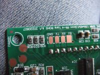
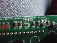
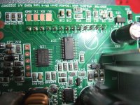
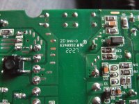
How do you identify markings on PCBs (large amount of Numbers) to find out the Manufacturer
- Parts
- 4 Replies
I ask not about component resp. part numbering like Q1, D1, R1, C1, L1.
Also not about RU stamp (a type of safety certification mark issued by UL Solutions) - go to
http://www.58pcba.com/index.php?id=429
https://en.wikipedia.org/wiki/UL_(safety_organization)
https://electronics.stackexchange.com/questions/226521/what-does-ru-ur-label-on-dc-power-relays-mean
It's about numbering related to the printed circuit board itself.
I want to find out the actually manufacturer with help of these amount of numbers for those cases, where I don't get technical manuals when contacting the brand that is to read outside of the envelope.
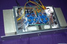
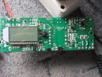
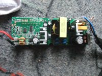
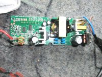
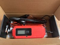
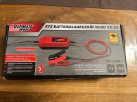
The attached image show the PCB markings of an "Ultimate Speed Battery Charger" - German's model "ULGD 5.0 D2" (2516) - go to
https://www.kaufland.ro/content/dam...nd-motorcycle-battery-charger_ULGD-5.0-D2.pdf
I guess, a lot of other models/brands use an identical PCB, made in China.
For this PCB charger unit I need a schematic diagram, that isn't available from the German distributor.
How can I identify the manufacturer based on these numbers?
Thank you very much for an information so as posting appropriate URL's concerning this.
This URL's don't provide the wanted hints.
https://absolutepcbassembly.com/pcb-markings/
https://www.quora.com/What-do-the-PCB-markings-mean
https://www.analog.com/en/technical...d-identification-using-1wirereg-products.html
https://www.cognex.com/industries/electronics/pcb-assembly/board-identification
P.S.: the silver heatsinks and the electrolytics close to the heatsinks runs very hot while operation without cover (approximately 100-110 °C).
Also not about RU stamp (a type of safety certification mark issued by UL Solutions) - go to
http://www.58pcba.com/index.php?id=429
https://en.wikipedia.org/wiki/UL_(safety_organization)
https://electronics.stackexchange.com/questions/226521/what-does-ru-ur-label-on-dc-power-relays-mean
It's about numbering related to the printed circuit board itself.
I want to find out the actually manufacturer with help of these amount of numbers for those cases, where I don't get technical manuals when contacting the brand that is to read outside of the envelope.
The attached image show the PCB markings of an "Ultimate Speed Battery Charger" - German's model "ULGD 5.0 D2" (2516) - go to
https://www.kaufland.ro/content/dam...nd-motorcycle-battery-charger_ULGD-5.0-D2.pdf
I guess, a lot of other models/brands use an identical PCB, made in China.
For this PCB charger unit I need a schematic diagram, that isn't available from the German distributor.
How can I identify the manufacturer based on these numbers?
Thank you very much for an information so as posting appropriate URL's concerning this.
This URL's don't provide the wanted hints.
https://absolutepcbassembly.com/pcb-markings/
https://www.quora.com/What-do-the-PCB-markings-mean
https://www.analog.com/en/technical...d-identification-using-1wirereg-products.html
https://www.cognex.com/industries/electronics/pcb-assembly/board-identification
P.S.: the silver heatsinks and the electrolytics close to the heatsinks runs very hot while operation without cover (approximately 100-110 °C).
Attachments
-
 DSCF8806.JPG710.1 KB · Views: 196
 -
 DSCF8804.JPG738.7 KB · Views: 190
 -
 DSCF8805.JPG698.8 KB · Views: 176
 -
 DSCF8802.JPG705 KB · Views: 169
 -
 DSCF8800.JPG674.5 KB · Views: 166
 -
 DSCF8798.JPG720 KB · Views: 191
 -
 DSCF8799.JPG612.6 KB · Views: 162
 -
 DSCF8808.JPG691.6 KB · Views: 182
 -
 45e864c0-dc81-4a71-a5e6-b85ca977471c.jpg91.4 KB · Views: 173
 -
 e5a6aeae-0889-4bd5-a994-24d256107473.jpg137 KB · Views: 151
 -
 e0758193-3f8d-4092-953f-badcf589b7c9.jpg93.8 KB · Views: 183
Hello from Austin TX
- By mgrisoli
- Introductions
- 3 Replies
Hello, I am Marcelo I live in Austin, TX, United States.
My father retired as an electronic technician, he used to inspect admiral TV set production lines in a plant they had in Brazil.
I have a minor in electronics with major in information systems. Although I never worked with electronics until I developed a passion for vintage audio gear.
Now I restore vintage audio gear from the transistor era as a hobby.
I take pride in my work even though it is always a humbling experience.
Normally the equipment I restore comes out as good or better than original in terms of sound and I do what I can to help on the cosmetics.
My preferred approach goes much beyond a recap job.
Some other old farts love to hang out in my garage during the weekend to bring me stuff to look at, drink some beers and tell tales about their time in the industry/army/field, but I am sure they are just hiding from their wives.
I say it is all fine as long as they stop trying to make me fix their lawn mowers.
Joining you
- By JKiriakis
- Introductions
- 9 Replies
Interested currently in building a solid state amp. Recently completed three EL84 based point to point SEP amps from scratch based on known good circuits, some leftover bits from tube guitar amps built ~ a dozen years ago, figured may as well go for it. Of course it started with one and led to three. Acquired two more vintage SS preamps (now have three Superphon Basics running). Two Dual 1019 idler decks and a Magnavox CD610 (dual DAC / Belgium). Three sets of home build OB speakers, coral holey baskets, Diatone 610 reproductions and Betsy's. Also have a couple quite old console pull tube SETs one at work nearfield and another in the garage.
NAD 3020 (1982/3) - loud pop when turning on
- By hrp1000
- Solid State
- 23 Replies
I have a NAD3020 (from new, bought in 1982 or 1983) that has recently developed a loud pop when turning on. This is the original, not the 3020A or later, as far as I can tell, but s/n A3257885 might reveal something else!
It makes no difference where the volume is set prior to turning on, but having the "Audio Muting" button in makes the pop much quieter.
Before I open it up and start checking things with a multimeter, which are the likely components that have failed?
It makes no difference where the volume is set prior to turning on, but having the "Audio Muting" button in makes the pop much quieter.
Before I open it up and start checking things with a multimeter, which are the likely components that have failed?
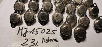
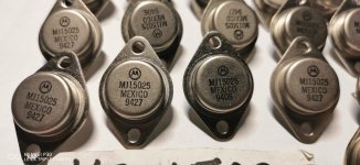
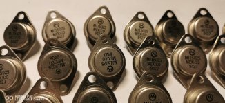
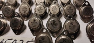
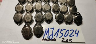
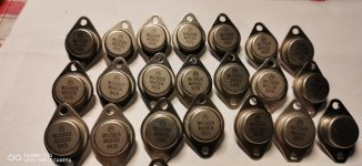
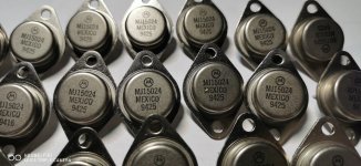
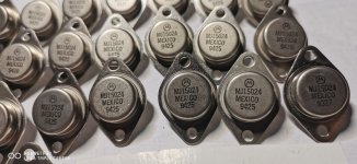
For Sale 46 piece MJ15024 & MJ15025 Motorola
I have 23 Pair MJ15024 & MJ15025 / BJT 16A 250V 250W Motorola. All with Production Date stamps from 1994. These were bought from a Motorola Distributor in Germany. Clear up my semiconductor collection of the ones I don't need anymore. The sale only takes place if all transistors are purchased. The price does not include PayPal and shipping costs. I can only shipped from Germany of the parcel weight. PayPal is accepted, only registered shipping possible, the buyer pays the additional 5% PayPal fees, a payment as PayPal / friend does not account for the 5% and can be shipped without tracking, the shipping costs within the EU are about €19 - €24. Outside the EU it may vary by country. A combined shipping is possible but will change the shipping costs a bit. If you are interested send me a PM.
Attachments
-
 IMG_20230321_054908.jpg276.3 KB · Views: 132
 -
 IMG_20230321_054912.jpg288 KB · Views: 80
 -
 IMG_20230321_054915.jpg288.2 KB · Views: 126
 -
 IMG_20230321_054919.jpg293.5 KB · Views: 68
 -
 IMG_20230321_055238.jpg242.7 KB · Views: 84
 -
 IMG_20230321_055240.jpg283.3 KB · Views: 69
 -
 IMG_20230321_055247.jpg322.8 KB · Views: 72
 -
 IMG_20230321_055250.jpg326 KB · Views: 60
 -
 IMG_20230321_055253.jpg310.1 KB · Views: 83
Bashō SE Class A Amplifier
- By Dibya
- Headphone Systems
- 17 Replies
Matsuo Bashō was one of the famous Japanese Zen master from 17th Century.
As Zen teaches to live a Simple lifestyle, I thought of creating a Simple SE Class A headphone amp which can even be used a line pre amplifier. Been a Fan of Class A single ended design , very day i tried PCA designed by XRK971.
Initial Gain Stage that i made with two 2SK209GR and one resistor,
Results are still impressive , on 20K load it archived
Harmonic Frequency Fourier Normalized Phase Normalized
Number [Hz] Component Component [degree] Phase [deg]
1 1.000e+03 1.718e-01 1.000e+00 180.00° 0.00°
2 2.000e+03 1.117e-04 6.501e-04 89.82° -90.18°
3 3.000e+03 1.368e-06 7.966e-06 -179.22° -359.21°
4 4.000e+03 2.014e-08 1.172e-07 -93.47° -273.46°
5 5.000e+03 2.958e-10 1.722e-09 31.05° -148.94°
6 6.000e+03 7.365e-11 4.288e-10 -138.89° -318.89°
7 7.000e+03 7.373e-11 4.292e-10 -170.78° -350.78°
8 8.000e+03 6.321e-11 3.680e-10 72.07° -107.93°
9 9.000e+03 5.146e-11 2.996e-10 -151.24° -331.24°
Total Harmonic Distortion: 0.065015%(0.065014%)
Now this topology needs to get muscular strength, I mean N Channel Mosfet.
I want to add Fairchild FQP30N06 as output buffer.

Ltspice Spice Sim is attached.
As Zen teaches to live a Simple lifestyle, I thought of creating a Simple SE Class A headphone amp which can even be used a line pre amplifier. Been a Fan of Class A single ended design , very day i tried PCA designed by XRK971.
Initial Gain Stage that i made with two 2SK209GR and one resistor,
Results are still impressive , on 20K load it archived
Harmonic Frequency Fourier Normalized Phase Normalized
Number [Hz] Component Component [degree] Phase [deg]
1 1.000e+03 1.718e-01 1.000e+00 180.00° 0.00°
2 2.000e+03 1.117e-04 6.501e-04 89.82° -90.18°
3 3.000e+03 1.368e-06 7.966e-06 -179.22° -359.21°
4 4.000e+03 2.014e-08 1.172e-07 -93.47° -273.46°
5 5.000e+03 2.958e-10 1.722e-09 31.05° -148.94°
6 6.000e+03 7.365e-11 4.288e-10 -138.89° -318.89°
7 7.000e+03 7.373e-11 4.292e-10 -170.78° -350.78°
8 8.000e+03 6.321e-11 3.680e-10 72.07° -107.93°
9 9.000e+03 5.146e-11 2.996e-10 -151.24° -331.24°
Total Harmonic Distortion: 0.065015%(0.065014%)
Now this topology needs to get muscular strength, I mean N Channel Mosfet.
I want to add Fairchild FQP30N06 as output buffer.
Ltspice Spice Sim is attached.
Attachments
My obsession with transformers. LED Driver question.
- By chinoy
- The Lounge
- 6 Replies
So i have a thing for transformers. Tiny ones, large ones, Im a hoarder and collect junk.
Has anybody looked into using LED drivers either contant voltage or constant current. In their audio world.
I picked up a huge box of blown LED bulbs in various wattages from the scrap yard.
They have a lot of parts on the little PCB. From transformers, to inductors to capacitors.
Before I go down the rabbit hole of trying to understand the various drivers how they work.
Has anybody else had this idea ?.
So far I have been just pulling polar caps off them. Decent quality well at least better than the china junk we get in our markets. 90% of the failures are LED failure or Electrolytic capacitor failure. Nothing ever happens to the other parts. On many the PCB is still working fine ie. you input 220vc and it outputs 12 v or 24v d/c.
I plan to hook up the output to the scope and start studying the circuits.
Amplifier for high efficiency speakers with 10mV - 1000mV out with low SNR, THD+N, and zero gain input, perfect with negative gain . It's possible?
- By inetboy
- Solid State
- 9 Replies
Amplifier for high efficiency speakers with 10mV - 1500mV out with low SNR, THD+N and zero gain input, perfect with negative gain . It's possible?
Anatomy of an output tube failure - dissection
- Tubes / Valves
- 25 Replies
I can't find anything like this online, so I thought I would put this here as a subject of general interest. Anyone who has read the thread about my ill-fated Chinese tube amplifier kit build knows that it is now dead after only 2 days with a bad output transformer. Details can be found there for anyone interested.
Below is a Chinese 6P14 output tube that failed on me after 48 hours of use. I very carefully disassembled it, and here is what I found. I hope I have everything labeled correctly. This is my first time inside a tube. I suspect it may be the first time for others also, which is why I consider this a matter of general interest to tube enthusiasts.

I didn't make those bends that you see in the distorted rods. They are extremely stiff, and they were that way when I gently slipped the internals out of the sheet metal outer envelope, which I assume is the plate, set off to the side out of the picture. On the left side, there is a metallic brown discoloration where the material in the tube discolored the glass envelope. On the right side, parts actually are in physical contact with each other, and that's how I found it when I carefully slid it out.
The Chinese 6P14 tube is well known for having an extremely weak and fragile screen grid, as well as very poor quality control, but surely it can't be normal for failed tubes to look this bad inside? Does anyone have any knowledge on this subject? I'm not sure how many people actually take the time to dissect a tube.
Below is a Chinese 6P14 output tube that failed on me after 48 hours of use. I very carefully disassembled it, and here is what I found. I hope I have everything labeled correctly. This is my first time inside a tube. I suspect it may be the first time for others also, which is why I consider this a matter of general interest to tube enthusiasts.
I didn't make those bends that you see in the distorted rods. They are extremely stiff, and they were that way when I gently slipped the internals out of the sheet metal outer envelope, which I assume is the plate, set off to the side out of the picture. On the left side, there is a metallic brown discoloration where the material in the tube discolored the glass envelope. On the right side, parts actually are in physical contact with each other, and that's how I found it when I carefully slid it out.
The Chinese 6P14 tube is well known for having an extremely weak and fragile screen grid, as well as very poor quality control, but surely it can't be normal for failed tubes to look this bad inside? Does anyone have any knowledge on this subject? I'm not sure how many people actually take the time to dissect a tube.
ICE50ASX2 ground wiring
- Class D
- 1 Replies
Hi!
I'm building two stand-alone speakers: three-way, one ICE50ASX2 (BLT) for each one. I thought i would just build a wood box, it'd be way more difficult to use metal or any other material. But since it's wood, how am i supposed to connect the ground wire? I know it can't go in the wooden box right? Every single amplifier built i've seen online (with the ICE50ASX2) is fit in a box made out of conductive stuff, so they would just screw the wire to the box. Where is the ground connection from the board to the box? I thought it may be on two of the four holes for the screws, but i can't find this information anywhere.
thank you!
(i'm talking about the two holes on the left)
Ultimate audio interface for home studio/workshop?
- PC Based
- 6 Replies
I am looking around for a digital mixer style interface that also is a control surface for DAW. Any recommendations for a unit that can also double up as a workshop interface for sending chosen signals out to test circuits and speakers and things. This would mean at least a secondary set out outputs that can run to the workshop bench in the same room as well as at least pres on six channels so that I may have a spare pair for the workshop as I need just 4 for my studio
This looks like a discontinued product that might have done the job at a good price
https://www.swamp.net.au/icon-aio6-usb-audio-midi-device-and-control-surface
The Roland MX1 is another discontinued one. It didn't have pres, but I am open to using dedicated mic and instrument pres if a good console like this is limited to line level inputs only
A problem with both is a lack of enough knobery for the channel strips. Dedicated knobs for bass, mid, treble are important for me
I am also a bit shy of Harmon products as I have noticed a good deal of digital equipment under the various brands being offered for second hand sale without the PSU and turning out to be bricked. I got done once on a Gumtree purchase too
At some point in the near future, I would like to get a Roland VT4 each for my four vocal mics. This gives me 4 dedicated pres that are audio interfaces too. Under Apple, this can be seen as one set, so I might only need a control surface. With so many different solutions available, my head is in a spin trying to follow a direction. Do folks here have any experience with this? What has worked for you?
Thanks and regards
Randy
Free (New, Never Used) Dayton Audio Grade Caps! Who wants 'em?
Hello everyone.
I have a friend who has some new, never used Dayton 250V metalized polypropylene audio grade caps to give away for the price of postage. There are four pairs of caps and you must take them all. Cap sizes are 3.3 uF, 4.7 uF, 6.8 uF, 10 uF and 12 uF. Here's a link to one of the sizes on Solen.ca so you can see what type they are.
https://solen.ca/en/products/dmpc-12
They bought these capacitors from Solen.ca and I was going to use them to upgrade the capacitors on the crossovers in a pair of speakers that they had. I don't recall what speakers they were but they were cheap and the only reason we wanted to upgrade them was because they were about the only speakers that would fit into cubby holes that the previous owner of the house had custom made to fit the speakers into the false wall. We figured that if they were stuck using those speakers, we might as well make them sound as good as we can.
Anyways, we got the caps and then for one reason or another we kept putting of the upgrade and just never got around to upgrading the speakers with them. Then they moved several hundred miles away and sold the speakers with their audio system but forgot they had the caps stored somewhere in a box. They just came across them again and want to get rid of them. I don't know when I'll be doing a speaker project next and who knows if I'll need any caps of any of those sizes so I'm hoping someone here can make good use of them.
My friend just wants them to go to a good home where someone can use them. All she wants is the cost of postage covered. The postage would be from Victoria, BC, Canada. The package will be small and light so it probably won't cost more than $20 to send them anywhere. If you can give me your zip or postal code, I can figure out what the postage will cost. Then you can send her the money to cover the postage via eTransfer if you're in Canada or PayPal if you're elsewhere and she'll mail you the package. Easy-peezy!
The first person to PM me gets them! If you give me your cell no. in the PM, I can text you some photos of the actual capacitors if you want to see them and verify the authenticity of this post.
Simple question regarding example capacitor in circuit, advice please
- By ronoandk
- Solid State
- 4 Replies
Hello. Once again I am coming to the well to seek advice from those who don't mind assisting a relative novice. My question(s) are simple, please refer to the enclosed schematic (HK Citation 16A, output section), C3 and C4 (both 10uf 150V).
1. These serve as "bypass" capacitors? If not then?
2. I don't have polarized electrolytic in stock, but I do have non polarized 250V polypropylene in 10uf. Can I safely (and without unintended circuit consequences) substitute?
3. Lastly, electrically, it doesn't matter where on the respective supply rail they are located?
Thank you in advance. I appreciate you help
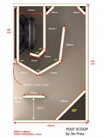
12 inch subwoofer for my home system (first build ever) MINI-SCOOP (?)
- By gigio9696
- Subwoofers
- 17 Replies
Hello everyone,
I'm new to the forum and first I would like to thank all the members who contribute every day to share precious knowledge about diy sound system builds.
About my question:
I'm aiming to build a 4-way sound system inspired by typical systems used for dub/reggae music but in a smaller size. The system will be an home system, hopefully usable for small parties with max 20 guests.
I've already found a box design that I would want to use for mid-bass (kick) (already build but not loaded with the raccomended driver): the design
I've spoken to Jim Frize (the designer of the box mentioned above) a couple of days ago and he suggested me to pair it a whit a 2x12 inch scoop or a double 12 inch ported enclosure to hit the low-bass.
However, I'd like, just temporarily, to pair it with a single 12 inch mini scoop for economic and transport reasons. I know that, going this way, I probably can't hit low enough but it's ok for now on been my first build ever.
I've seen a lot of build plans for a 12 inch mini scoop just searching on Google "12 inch mini scoop" but all raccomended drivers are too expensive for me or not mentioned at all ( something like: "just use a 12 inch driver, no matter which u choose" but if i learned something in the last couple of months, scraping web pages for infos, is that this is not the way to handle DIY SS builds ).
I'm looking for a driver in the 80-120€ price range.
Here some drivers that I've seen but I didn't know exactly if they are good for what I'm trying to achive:
From Italy 🙂
I'm new to the forum and first I would like to thank all the members who contribute every day to share precious knowledge about diy sound system builds.
About my question:
I'm aiming to build a 4-way sound system inspired by typical systems used for dub/reggae music but in a smaller size. The system will be an home system, hopefully usable for small parties with max 20 guests.
I've already found a box design that I would want to use for mid-bass (kick) (already build but not loaded with the raccomended driver): the design
I've spoken to Jim Frize (the designer of the box mentioned above) a couple of days ago and he suggested me to pair it a whit a 2x12 inch scoop or a double 12 inch ported enclosure to hit the low-bass.
However, I'd like, just temporarily, to pair it with a single 12 inch mini scoop for economic and transport reasons. I know that, going this way, I probably can't hit low enough but it's ok for now on been my first build ever.
I've seen a lot of build plans for a 12 inch mini scoop just searching on Google "12 inch mini scoop" but all raccomended drivers are too expensive for me or not mentioned at all ( something like: "just use a 12 inch driver, no matter which u choose" but if i learned something in the last couple of months, scraping web pages for infos, is that this is not the way to handle DIY SS builds ).
I'm looking for a driver in the 80-120€ price range.
Here some drivers that I've seen but I didn't know exactly if they are good for what I'm trying to achive:
- Fane Sovereign 12-300
- the box Speaker 12-280/8-W
- Turbosound TS-12W350/8A
From Italy 🙂
Attachments
HK730 issue - Right channel has no sound at startup until I turn volume way up.
- By rosenhauer
- Solid State
- 5 Replies
I've owned this HK730 since the late 80's it was my main unit through college but has since been relegated to a workshop system.
For the past 20+ years I've had an issue where the right channel won't produce any sound after it's been off for more than a few days. That is until I crank the volume up then it will come back on in a short static pop. Then I can turn the volume down and it works fine until I turn it off for a few days again. Years ago I discovered that I could turn off the speakers (deselect them) crank the volume for 2-3 seconds turn it back down and select the speakers again and all is fine.
I've gotten so used to it that I rarely think about it but was working on some other electronic projects and thought about it and decided to ask if anyone else had seen this before and if it's a quick fix. Years ago I looked for cold solder joints and used DeoxIT all of the switches/controls and the plugs between the boards. The only other thing I did, probably a decade ago, was to replace all of the lights with LEDs. Apart from the startup issue it sounds great and hasn't had any other symptoms.
Since it doesn't have to have a load when it's turned up I wasn't sure where to start looking.
Newbie - PA system setup
- By GeoffW53
- PA Systems
- 16 Replies
Hi,
A newbie here, both to this forum, and to PA systems! I'm just looking for some advice on which way to go in providing a PA system for voice (no music) that will be suitable for a room around 30mx12mx3m, with the capability of going slightly bigger, if necessary.
I was going to go down the passive route of a mic 4-channel pre-mixer into a power amp (behringer) then out into 4 speakers. But I wondered whether I should use 4 powered speakers and split the pre-amp output to each speaker?
Is that enough information to give me some advice, or do you need more info?
Thanks,
Geoff
Hypex SMPS3kA700 2 x 85 VDC 3000 Watt Switch Mode Power Supply
Brand new. Never used Hypex SMPS3kA700 2 x 85 VDC 3000 Watt Switch Mode Power Supply
Euro 220.- + shipping.

Euro 220.- + shipping.
2nd try single ended
- By redride27
- Tubes / Valves
- 32 Replies
I'm redoing an amplifier I built a few years ago using the same circuit using new parts (caps,sockets,enclosure,OT) I found diylayout creator and I'm hoping for a little critique.
I also now realize that nothing is drawn to scale and it might not fit. Lol It's 12x8

.jpg")
I'm a little fuzzy as to were the ground the dual .1uf feedback capacitors. Is it part of the small signal section that goes to the - cap on the 255v? Or is it part of the( -)in the B+ 265v section?
I also now realize that nothing is drawn to scale and it might not fit. Lol It's 12x8
I'm a little fuzzy as to were the ground the dual .1uf feedback capacitors. Is it part of the small signal section that goes to the - cap on the 255v? Or is it part of the( -)in the B+ 265v section?
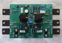
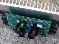
Musical Concepts PA8 / Exicon D.D.
- Solid State
- 7 Replies
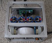
I designed and built 3 pairs of mono amps around the Musical Concepts PA7 MKII / PA8 and am super impressed with the PA-8, its layout, ease of installation and use. It sounds astounding, small amp delicacy and finesse, with HUGE AMP effortless ease and an unflappable sense of drive. I am struck by how quiet the amps are (no fan is nice) the music emerges from velvety (almost eerie) silence. These amps are rendering the most musical detail I have ever experienced with any of my amp builds or systems, without grain or etch... the music event is very relaxing, with a harmonic more like vacuum tubes. (without excessive heat or required fans)
I powered the amp up, checked / set DC offset, gradually brought the bias up... the most challenging part, as with any build, is the couple hundred hours of burn-in (as with most components). When something sounds like this, so great from the get-go, you know it will only get better and better. Incredible Macro and Micro dynamics, increased sense of space around instruments, with an immense sound field. I cannot say enough great things about the sum of my project(s) built around a known standard. I am also "burning-in" a Mundorf MLytic HC (LOCO cap) power supply version, not shown.
It was actually easy, I knew exactly what I wanted in a power supply, after designing, building and modeling dual mono supplies with Hafler 500/600 amplifier modules over the past 6-8 months. I have wanted a Driver PCB solution like this, although I was prepared "to hack" or reconfigure a PA7 to flat, into a point to point layout for the output stage. When John mentioned the TO-247 / TO-264 output option, I request / committed to 2 pairs right off the start... knowing just how great the PA7 is... this elegant circuit is a breakthrough in system transparency in the over a dozen amps I have used them in...
Background / my inspiration to do this... **I wanted to build something that I could not go out and buy**
I have *dreamed of* wanted to build *own* an amp like this for many years. I will just say it... I wanted an amp to "equal" and/or mirror my "old" Levinson No. 336, a beast for power, one that I could no longer pick-up after L & R shoulder surgerie(s), I sold it in 2011. The total / combined weight of my 2 channel beast, is about 15lbs. lighter than No. 336 and I can pick them up and carry them = A REAL WIN!!!
I believe these amps are more delicate, open (literally), equally powerful and do not require 50-60 amp electrical service to deliver spec... though I am considering wiring the main sound room with a 240v (amp) feeds... which is only 10 feet from my electrical panel. Where does this hobby end???
~ I will admit to buying most of the initial PA8 production run ~
I feel that certain = that confident in it to, build more amps...
with this most elegant DIY solution.
Attachments
10F vs W3 bamboo vs W4 bamboo vs Mark Audio for mid tweet.
- By Lawnboy
- Full Range
- 1 Replies
I want to employ a 3”-4” fullranger as mid/tweet to control dispersion on a bookshelf build which will be placed in corners. I really like the looks of the 10F on paper and in bikinpunks measurements but the Tang bamboos are half the price and the reviews are shining. Upper sparkle isn’t a priority while a smooth off axis response is otherwise I’d go with the RS100. The Marks are also on my radar. I’m limiting my choices to drivers with perfect circle frames aka no fatal drivers with those screw holes that stick out or the many full range drivers with the square-ish frames. 90db maximum is desired with a crossover anywhere around 200-600 hp. What do y’all think?
Modifying transistor spice models to simulate typical device spread
- By mz543578854
- Software Tools
- 0 Replies
Hi, I want to simulate effects of serial "spread" of small signal and power transistors in an amplifier circuit in LTSpice.
The transistors are BC550 / BC560 and MJ15003 / MJ15004.
Which of the spice parameters of these should I vary to which degree to mimick realistic differences of unmatched devices? hFE (BF) is pretty clear, somewhere I found a pointer that IS is related to Vbc, but I have no clue how much to change, if at all correct.
Any advice?
Thanks,
Mo
The models I am using are
.MODEL MJ15003 npn
+IS=1e-09 BF=226.431 NF=0.85 VAF=43.4348
+IKF=10 ISE=1e-08 NE=1.79698 BR=1.65466
+NR=1.5 VAR=434.348 IKR=4.42319 ISC=5.49997e-09
+NC=3.18751 RB=43.922 IRB=0.1 RBM=0.1
+RE=0.0001 RC=0.20765 XTB=0.746102 XTI=1
+EG=1.05 CJE=9.62276e-08 VJE=0.505131 MJE=0.650363
+TF=9.99972e-09 XTF=1.35733 VTF=0.996711 ITF=0.999802
+CJC=1.22855e-09 VJC=0.95 MJC=0.23 XCJC=0.803115
+FC=0.638728 CJS=0 VJS=0.75 MJS=0.5
+TR=1e-07 PTF=0 KF=0 AF=1
.MODEL MJ15004 pnp
+IS=1e-09 BF=226.431 NF=0.85 VAF=43.4348
+IKF=10 ISE=1e-08 NE=1.79698 BR=1.65466
+NR=1.5 VAR=434.348 IKR=4.42319 ISC=5.49997e-09
+NC=3.18751 RB=43.922 IRB=0.1 RBM=0.1
+RE=0.0001 RC=0.20765 XTB=0.746102 XTI=1
+EG=1.05 CJE=9.99946e-08 VJE=0.4 MJE=0.658304
+TF=9.99976e-09 XTF=1.3573 VTF=0.996475 ITF=0.99985
+CJC=1.22854e-09 VJC=0.95 MJC=0.23 XCJC=0.803124
+FC=0.761291 CJS=0 VJS=0.75 MJS=0.5
+TR=1e-07 PTF=0 KF=0 AF=1
.MODEL BC550C npn
+IS=45e-15 BF=689 VAF=162
+IKF=0.09 ISE=4600e-15 NE=2 NF=0.9965
+RB=167 RC=1 RE=0.04
+CJE=18.7e-12 MJE=0.35 VJE=0.75
+CJC=6.2e-12 MJC=0.25 VJC=0.4 FC=0.5
+TF=595e-12 XTF=10 VTF=10 ITF=1
+TR=10e-9 BR=12.2 IKR=0.34
+EG=1.2 XTB=1.65 XTI=3 NC=0.996
+NR=1.0 VAR=120 IRB=7e-5 RBM=1.1
+XCJC=0.6
+ISC=5e-15 mfg=CA030111
.MODEL BC560C pnp
+IS=60e-15 BF=900 VAF=160
+IKF=0.10 ISE=70e-15 NE=1.42 NF=1
+RB=170 RC=1.0 RE=0.05
+CJE=19e-12 MJE=0.3 VJE=0.75
+CJC=3.9e-12 MJC=0.3 VJC=0.75 FC=0.5
+TF=600e-12 XTF=7 VTF=4 ITF=0.45
+TR=10e-9 BR=3 IKR=0
+EG=1.1 XTB=1.5 XTI=3 NC=2
+ISC=0 mfg=CA030211
Free or Trade: JBL 2217HPL (Pair) - Wash DC Metro Area Local Pickup Only
I have a pair of JBL 2217HPL drivers in EXCELLENT Condition. I've been holding on to them thinking I'll build an econowave - or something of the likes one day - but I just no longer have interest in pursuing that project.
They are free for local pick up (or if you have some drivers in your inventory that you too likely don't see yourself using - perhaps we can trade).
Again - trade is not mandatory - I'll be just as happy giving them away for free.
They are free for local pick up (or if you have some drivers in your inventory that you too likely don't see yourself using - perhaps we can trade).
Again - trade is not mandatory - I'll be just as happy giving them away for free.
Will KEF speakers work with powered mixer?
- By Frontman1
- PA Systems
- 10 Replies
Hi All,
I have a friend who's son is starting a band and he's trying to put together a cheap PA just for a bit of foldback.
To save money he wants to use a couple of KEF speakers he already owns with the little powered mixer he's getting for them.
The speakers are KEF Q55 150W 6 Ohms each. The mixer is a SubZero SZ-PMIX4 from Gear for Music's website, which shows the output on the back plate as 8 Ohms.
It also shows the output of the mixer as 175W peak.
Do you think the speakers will work on that, he's worried about blowing them but doesn't want to have to buy passive speakers at this stage if he can avoid it, while this is just a bit of fun for the youngsters while they're starting out?
Dual cold clipper thoughts anyone?
- By dtbradio
- Instruments and Amps
- 8 Replies
I'm toying with the idea of building a high-gain amp with two cold clipper stages in order to get more asymmetrical clipping and harmonics. The second clipper will be preceded by an attenuator and a typical gain stage to keep the clippers in phase with each other. Dual cold-clipping may have been done before, but I haven't seen any dual-cold-clipper circuits in any amp schematic I've come across so far. Before I do any actual building, I'd like your thoughts, good/bad/indifferent, on the idea in general, and on my preliminary circuit design (schematic attached below). All input is welcome and valued!
Attachments
Revogi SOW323 power strip diagram
- By TDA7386
- Everything Else
- 0 Replies
Hello everyone. I am trying to repair a smart wifi strip, but there are some ferrite inductors that do not have any specified value. I need the schematic if possible or some way to know what the value is. Its size is 7x5mm but there are many different values for those measurements. The model is Revogi SOW323. Thanks in advance.
M1 Mac Fi
- By jheoaustin
- PC Based
- 0 Replies
Hi everyone,
I had been haunting the surround processor part of the forum for a while to complete my HT/music system with built-in DSP active crossovers. I had some luck a few years ago to hack and modify Monolith HTP-1 to achieve that. I still have some issue though, such as difficulties to modify/debug/build the DSP F/W, sample rate limit at 48kHz engaging Dirac Live 3 room correction, and the limit on the number of output channels. So I am turning my eyes into the computer-based sound card systems to eliminate such limits.
Since new M1 Mac mini is affordable, quiet and very powerful in processing, I am looking into M1 Mac mini + 16+ch USB DAC (+ preferably multichannel analog volume control somehow). I can write my own processing code which is actually quite simple(duplicate channels, FIR, sum channels, delay) but I didn't see a good support on doing such things on my own. As an alternative, if some S/W on Mac can just let me add an FIR and delay, that would probably fit the bill. I also want to run 4k BD UHD player S/W, Apple Music or Qobuz, and VLC for files, followed by Dirac Live then the DSP processing support I mentioned in a cascaded manner. If there is a good S/W for this, I'd love to know about it.
I am very new, or even haven't started in this area yet, so am humbly asking for helps in finding the right H/W and S/W. If someone knows how to program a plug-in into MacOS audio driver, I am willing to take on it, too. Looking forward to great helps from knowledgeable and experienced members here.
Regards,
Jay
WTB Iancanada FifoPi Q1/Q2
Hello,
I need 2 working first gen FifoPis. The ones that can be powered via the 5v gpio pins on the clean side.
Preferable in the EU.
Thanks!
I need 2 working first gen FifoPis. The ones that can be powered via the 5v gpio pins on the clean side.
Preferable in the EU.
Thanks!
Aperiodic port position
- By vrbbra
- Full Range
- 6 Replies
What is better option use aperiodic port in front or back or side panel of speakers?
Transformer/Choke? with 3 wires.. from old TV
- By efm7
- Tubes / Valves
- 5 Replies
Hi, I have a collection of these transformer/choke looking things that i’ve salvaged from various TVs over the years. I’m wondering what they are.
They have 3-wires, and when i search “3-wire transformer” I don’t get any relevant results on google.
Are they chokes, autotransformers, or something else? they seem to measure quite high in terms of DCR (1.2k ohms) and inductance (40H) with the center tap being quite close to one of the ends.
I’ve tried to look for old TV schematics to see if i can spot something that might be them, but i’m either not finding the right schematics or I’m not looking for the right symbols.
Please help!
Mark Levinson power amp No 23 that won't turn on!
- Solid State
- 6 Replies
Hello everyone! I have a Mark Levinson power amp No 23 that won't turn on!
After pressing the switch, the red LED lights up for a very short time and then goes off immediately!
Thank you for your support!
After pressing the switch, the red LED lights up for a very short time and then goes off immediately!
Thank you for your support!
Attachments
Car radio valves 12AL8, 12DY8 max power
- By pcardoso73
- Tubes / Valves
- 33 Replies
Hi,
I would like to give a try in designing a guitar amp using a low voltage valve.
I bought a 12dy8 but the datasheet doesn't state the maximum power. The same applies to many other low voltage valves.
To me should be max voltage x max current.
Can anyone help me with this,please?
Thanks in advance.
Cheers
Pedro
3-Way Crossover Upgrade Help Sought
I have four Cerwin Vega CLS-215 3-way speaker enclosures in a home audio system powered by a Crown XLS 2502 and everything calibrated via Mini DSP/REW with very good results. The crossovers employ inexpensive parts, including cheap poly caps, several electrolytics, inexpensive iron core inductors, cement resistors, etc. I would like to upgrade the crossovers and speaker wiring.
CV was unwilling to provide a schematic for the crossover, although I was able to find front/back images of the PCB and most parts values. I’ll get the rest when I remove one (a bit of a pain). My plan is to upgrade key components in the crossovers while sticking as closely as possible to the original parts values. I was able to draw this schematic, which you can see attached here.
From the research I’ve done, I gather that capacitor upgrades would be C1, C2, C3/C4, C5, and C6 in order of importance. Space permitting, I will try to get rid of the electrolytics, or perhaps just construct new crossover boards from scratch if it makes sense.
I realize there is a debate as to the effectiveness of a small bypass cap in the tweeter circuit (and midrange?). If I were to use one, would that be on C1 or C2?
I’d like to go with air inductors (tweeter and midrange) if I can match the resistance of the originals. If not, I’m considering just upgrading all to better laminate types.
Unless the values are out of whack, I’m not sure if it’s worth upgrading the resistors.
There is a PTC resettable fuse on the tweeter positive output. I have no plans to remove it unless it adversely affects the sound quality(?).
What changes would you make? Opinions welcomed and greatly appreciated!
Attachments
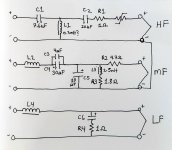
Which 'Nobsound' amp is this?
- By chumingo
- Solid State
- 27 Replies
Can anybody decipher what circuit topology or amp clone is being sold here, if any know?
https://doukaudio.com/collections/a...power-amplifier-stereo-single-ended-audio-amp
The build seems convenient for me to drive some old Braun 2-way boxes but would like to know more about it, as it is being sold for 200€ and I have no time to build one atm.
Weird that they mention electronic active filtering, but I only see some inductors in the pics which makes me think it’s passive.
Probably a JLH1969? Anyone heard experiences with this particular brand model?
Parts order
Not sure if this forum is correct,
I’m having way too much trouble figuring out how to be sure I’m ordering the correct part. For instance I’m trying to build a P3A amplifier (Rod Elliott). Typical example: I want to order a 22k ohm 1/4 watt metal film 1% resistor. The lead spacing is shown as 10.16mm (.4”).
How do I read the data sheet to correctly identify this lead spacing?
There are always several parts available with the same description but different part numbers. Reading the data sheet to differentiate each is, for me, very difficult. I don’t see anything in the data sheet that corresponds to the required/suggested lead spacing. I’m a an older rookie trying to get through this.
Please advise
Part of the issue is that the recommended spacing doesn’t match up exactly with the data sheet. So I have to select the next size down which still has all other parameters correct.
Thermistor location for psu
- By goodguys
- Power Supplies
- 4 Replies
Hi Thanks for reading. I have a large transformer and want to use a soft start as the mains keeps tripping everytime i plug the transformer in.
In the pass labs f5 amp they use a single thermistor in between the two primary windings. The transformer i have is encapsulated so cannot access the windings. I have the two mains cable live and neutral sticking out of the encapsulation, and four cables for the two secondary windings
Where can i put the thermistor, and which thermistor would you use for british ac 240 volts, something rugged.
The two secondaries are 15 amps each
Thanks
Measured Free Air Parameters with DATS vs Published TS Parameters
- By MalVeauX
- Subwoofers
- 21 Replies
Hi all,
Simple discussion, we often model with the published specs but what if the specs are different? I was measuring a driver today that I was working with and for the S&G's I did the free air parameters measurements after calibrating and I did it both wired as a single voice coil and dual voice coil in series to see if it changes anything significantly. I didn't think much of it. But then I looked at the published TS parameters and they're different. Not wildly different. But maybe different enough that I should model an enclosure for this particular driver based on my measured value or is this too getting into minutia and published values are fine?
The driver is a Dayton MX15-22.
Here's their published TS parameters:

And here's the DATS information I got from my particular copy of this driver (single and dual voice coil in series measured):


I noticed right away the impedance curves are different from the published. Instead of peaking on 20hz, it's right-shifted to 25~26hz or so? The Fs measured at 25.47~25.7hz instead of 21.7hz per the publication. And of course some values are different depending on using one voice coil at 2ohm vs two voice coils in series at 4ohm. I assume I should model using the two voice coils in series' values?
Do I need to input the Vas and do the measured mass here, my understanding is that won't effect the TS parameters already listed with measured value.
Very best,
Simple discussion, we often model with the published specs but what if the specs are different? I was measuring a driver today that I was working with and for the S&G's I did the free air parameters measurements after calibrating and I did it both wired as a single voice coil and dual voice coil in series to see if it changes anything significantly. I didn't think much of it. But then I looked at the published TS parameters and they're different. Not wildly different. But maybe different enough that I should model an enclosure for this particular driver based on my measured value or is this too getting into minutia and published values are fine?
The driver is a Dayton MX15-22.
Here's their published TS parameters:
And here's the DATS information I got from my particular copy of this driver (single and dual voice coil in series measured):
I noticed right away the impedance curves are different from the published. Instead of peaking on 20hz, it's right-shifted to 25~26hz or so? The Fs measured at 25.47~25.7hz instead of 21.7hz per the publication. And of course some values are different depending on using one voice coil at 2ohm vs two voice coils in series at 4ohm. I assume I should model using the two voice coils in series' values?
Do I need to input the Vas and do the measured mass here, my understanding is that won't effect the TS parameters already listed with measured value.
Very best,
NFB tone controller
- By Zohaib Ahmad
- Solid State
- 0 Replies
I need component values for nfb tone controller the schematic is given below is with out component value the use of 50k linear pots will be better.

Heptode curves
- By pcardoso73
- Tubes / Valves
- 35 Replies
Hi
I am trying to build an amp using an ECH83 valve/tube.
However, the curves in the datasheet mean little to me, since I can't plot a load line as normally I would do for a Pentode.
Anyone can explain this to me please?
Datasheet
http://www.r-type.org/pdfs/6ds8.pdf
Best regards
Pedro
I am trying to build an amp using an ECH83 valve/tube.
However, the curves in the datasheet mean little to me, since I can't plot a load line as normally I would do for a Pentode.
Anyone can explain this to me please?
Datasheet
http://www.r-type.org/pdfs/6ds8.pdf
Best regards
Pedro
Why Madisound recommends .8 Qtc enclosure for luxury 💰 mids?
- Multi-Way
- 23 Replies
Hi!
TLDR: Why is Madisound (ultra-high-end speakers) recommending an enclosure with a Qtc of .8 for my mids?
https://www.madisoundspeakerstore.com/approx-5-woofers/scanspeak-15w/8530k-01-5-revelator-woofer/ (.3 cuft + 20% fill)
LONGER VERSION:
I am building a 4-way system using active crossovers (MiniDSP Flex8). I was big into hi-fi car audio when I was young. I am fanatical about sound quality but I also want the music to have... impact. Read: I will be using a VERY generous house curve 😎.
I plan on running 2 of the mids linked above, and 2 more 7-inch drivers to manage the transition from thunderous bass to the high frequencies. I will need a lot of juice between 80hz and 200 hz to do it properly. The box recommendations for the 7s are similar in having a high Qtc.
On paper the higher Qtc is a good thing for this setup. I get a boost in this mid-frequency range BUT, what looks good on paper doesn't always sound good to the ear. I do not want to hear the speakers, I want to hear music. In the low range, I typically associate "invisible speakers" with transient response, which is achieved with a LOW Qtc (~.5). I am not sure if this applies to the midrange the same way it would to a subwoofer.
I don't really want to build multiple boxes to test. Do you have any experience with this? Thanks gang!
For Sale Darlington Transistors BDV64B & BDV65B Motorola
I have 35 x BDV64B Motorola, 4 x BDV64B Texas and 35 x BDV65B Motorola. The transistors are about 30 years old and have not been needed since then. These transistors are suitable Darlington pairs for amplifier output stages. Clear up my semiconductor collection of the ones I don't need anymore. The sale only takes place if all transistors are purchased. Offers are welcome. The price does not include PayPal and shipping costs. Can only shipped from Germany , prices are much lower above 200gr Parcel weight. PayPal is accepted, only registered shipping possible, the buyer pays the additional 5% PayPal fees, a payment as PayPal / friend does not account for the 5% and can be shipped without tracking, the shipping costs within the EU are about €15 - €17. Outside the EU it may vary by country. A combined shipping is possible but will change the shipping costs a bit. If you are interested send me a PM.
Attachments
-
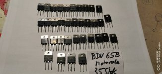 BDV64B & BDV65B Moto (1).jpg212.7 KB · Views: 65
 -
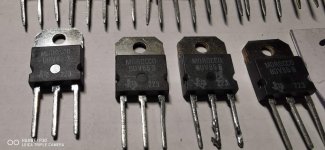 BDV64B & BDV65B Moto (2).jpg268.8 KB · Views: 61
 -
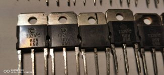 BDV64B & BDV65B Moto (3).jpg264.7 KB · Views: 56
 -
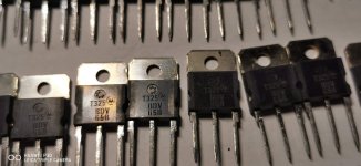 BDV64B & BDV65B Moto (4).jpg246 KB · Views: 72
 -
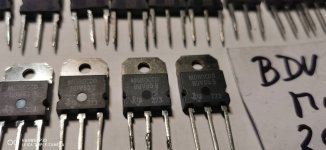 BDV64B & BDV65B Moto (5).jpg240.3 KB · Views: 85
 -
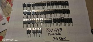 BDV64B & BDV65B Moto (6).jpg251.4 KB · Views: 96
 -
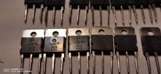 BDV64B & BDV65B Moto (7).jpg249.1 KB · Views: 71
 -
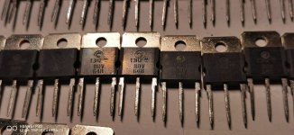 BDV64B & BDV65B Moto (8).jpg315.1 KB · Views: 74
 -
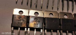 BDV64B & BDV65B Moto (9).jpg292.4 KB · Views: 77
 -
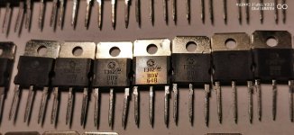 BDV64B & BDV65B Moto (10).jpg309.9 KB · Views: 43
 -
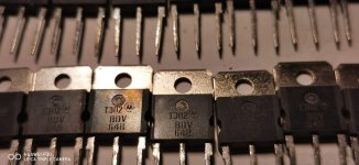 BDV64B & BDV65B Moto (11).jpg269.3 KB · Views: 85
Optim. OPT core dimensions
- By gorgon53
- Tubes / Valves
- 6 Replies
In a output transformer we want to have the highest inductance/leakeage inductance ratio.
I would have thougth that a shell type transformer with quadratic centerleg would give the highest ratio because of highést Afe/wirelength, but now i stumbled over this artikle from Crowhurst.
Can some one smarter than me figure out what those optimum ratios are, and why they are referenced to window heigth?
A/B = window length /window heigth
C/B = centerleg width/window heigth
D/B = stack thickness/window heigth
Thank you
Attachments
For Sale Boston Acoustics Reference Monitors VR-M50
I have a beautiful set of Rare Boston Acoustics reference monitors, these are one of the last and the Top tier of the Jynnfield line up. Beautiful real cherry wood veneer excellent proprietary drivers including the AMD tweeter. Im triming down a bit of my collection and would like see go to a good home.
I am asking 250 shipped cont USA only Paypal payment, buyer pays fees
I am asking 250 shipped cont USA only Paypal payment, buyer pays fees
Attachments
-
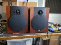 IMG_7853 2.jpg452.9 KB · Views: 73
 -
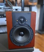 IMG_7909 2.jpg394.5 KB · Views: 94
 -
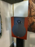 IMG_7950.JPG319.5 KB · Views: 66
 -
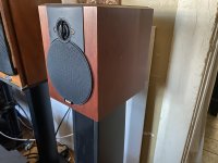 IMG_7953.JPG374.8 KB · Views: 61
 -
 IMG_7950.JPG319.5 KB · Views: 55
 -
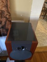 IMG_7949.JPG403.2 KB · Views: 52
 -
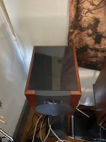 IMG_7951.JPG370.7 KB · Views: 56
 -
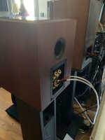 70103837809__4F7592BC-84D6-415C-88E8-C1EBE9327232.JPG309.8 KB · Views: 66
Scanspeak 15W8530K01 mid-woofers as bass drivers in a small 2-way (& maybe a Sub)?
Loss of space meant my last DIY 3-way speakers had to be dumped, and i rather lost heart. But I kept the drivers and those used for midrange were actually mid-woofers, the scanspeak 15W8530K01, which I liked very much and went nicely with the tweeters. So I was wondering about re-using them for a pair of small sealed 2-ways; I couldn't afford any other drivers of similar quality now.
Though I'm a bit concerned about the 'mid'-woofer designation; they are neither huge or exceptionally long throw. Perhaps they'd not be ideal, or maybe they would if complimented with a subwoofer (though it'd need to be fairly small).
Anyway, I'm only just starting to consider this, but just wondered if any more experienced members could spare me a sanity check first? Worth pursuing or just sell the drivers and start afresh with something else - probably cheaper but chosen specifically?
Cheers,
Kev
Reverse engeneering with VituixCAD?
- By Azrael
- Software Tools
- 4 Replies
I am planning to use a ribbon tweeter. I need to measure this with a pre-capacitor in order not to endanger my measurement amplifier.
It doesn't seem to be provided in VituixCAD, but is it possible to add it as a feature, that in such a case a back calculation is offered, how frequency and impedance response would look like without this protection capacitor?
I think such a feature could be useful in many other ways as well..... 😎
Best regards,
Michael
Translated with DeepL
JAMO 200 Subwoofer LED Status Light Fault
- By sporotite
- Solid State
- 0 Replies
Hi
The status light on the front of my sub no longer illuminates, otherwise the sub is working OK. Its a mini bi-colour LED. I have measured the voltage across the white connector on the board where the LED plugs in to and get -0.6v in standby and +0.6v powered on. I have removed the LED and tested it in diode mode with my multimeter; I don't get any readings. I have a spare mini bi-colour LED which tests OK on my multimeter (lights up) but when connected to the LED output on the sub I get nothing (presumably because the voltage is too low?)
Am I right in thinking the voltage is too low for this type of LED and what are the likely causes for this - anything a novice like me can investigate/fix? There seem to be lots of surface mount components around the connector, not sure I have the right tools or expertise to test any of these.
Any help/guidance gratefully received (please note I am being careful and staying well away from the high voltage side/caps etc..)
Question about three way switch Amp Camp v1.8, need help
- By Randy937
- The diyAudio Store
- 3 Replies
Hello,
My question is about the three way switch (blue switch) on the back panel of amp camp version 1.8. Based on the instruction pictures, it could be installed in two different ways, Does this switch have a "right side up"? Sorry for the elementary question, Im new but having fun with the assembly. Thank you in advance!
My question is about the three way switch (blue switch) on the back panel of amp camp version 1.8. Based on the instruction pictures, it could be installed in two different ways, Does this switch have a "right side up"? Sorry for the elementary question, Im new but having fun with the assembly. Thank you in advance!
WTB Original LM3875 or LM1875 chips (ideally LM3875TF)
- By uncle_leon
- Swap Meet
- 12 Replies
Hi, I need a couple of LM3875 to repair and old amp I made for a friend. If you have any original Texas Instruments chips I will pay good money for them. Only interested in originals originally bought from a reputable source such as Farnell or Mouser.
T.A.C. 34 Mk amp upgrade
- By Phatt
- Tubes / Valves
- 4 Replies
Hello there gents. Recently I got the amplifier of the title. I adjusted the bias and now I want to proceed to some upgrades. First of all I want to ask if someone has the schematic of this amp, I recon it used to be online some years ago but I can't find it online now. If someone can help me with this. Also if someone knows any recipe, values of parts(capacitors, resistors) that suit for this amp. Thank you so much in advance 😁


Mostly a Curiosity: Protruding Ports
Does it matter if a port protrudes beyond the outside of a bass reflex cabinet if its internal opening is in an appropriate place and the outer opening is in more or less free space? Is this a practical way to use a relatively long tube/port in a fairly small box for a stand mount where the port faces down through the stand, and is not too close to the legs?
Thanks,
Skip
Thanks,
Skip
KSS-151A Sony, compatible part to fix Sony CDP es series, will this work same as originals?....
- Digital Source
- 14 Replies
Hi guys, I recently (and finally) got able to buy a vintage CD player, in fact I have bought 2 Sony CDP-608ESD, they are working well and I love them, previously I use to own a CDP-X339es witch is already dead due laser issues, I would like to give a try to one of this chinese compatible part to check how they perform, so I can have it on hand on a future fix of the laser, I am pretty sure that will not last forever the ones I have right now, will this compatible part work same as the original?......
https://www.ebay.com/itm/1657371928...66QK6LUNw45gSA2x7FyGIzn7c=|tkp:Bk9SR7jAr4PJYQ
https://www.ebay.com/itm/1657371928...66QK6LUNw45gSA2x7FyGIzn7c=|tkp:Bk9SR7jAr4PJYQ
Attachments
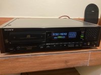
For Sale Lundahl Line input transformer LL1540xl
For sale 10 units Lundahl Line input transformer LL1540xl. SOLD


LT1085 constant current. will this work?
Can an LT1085 be used as a constant current LED driver? There is no mention of it in anywhere in the datasheet, but since this is an LM317 replacement can I use it the same way?

Attachments
DD M4a
- By mnhiphop101
- Car Audio
- 7 Replies
When I power the amp up the Drain on the low side of the output section slowly starts gaining voltage. This is without a single fet anywhere in the amp. Also the pin on the ps driver card that activates the relays alway has power. Even when I don't have any wires hooked up to it. It's holding onto what ever the b+ was at indefinitely.
Double horn for FE206e
- By p_ete2003
- Full Range
- 15 Replies
Hi, I finally have the space for big horns and my plan was to BIB the FE206e but then there's also Sachiko, Kirishima, Vulcan.. so I would like to hear your comments which one to build.
My room is appr 10m x 6m, corner loading is a problem and would like to put the horns near back wall. The Sachiko/Kirishima would be ok but Vulcan needs some breathing room behind the speaker? I have found 21mm BB ply for "good" price and that means I need to recalculate the part dims for Kirishima. Don't know about Sachiko because haven't seen the plans for it.
So here's my thoughts:
-BIB: I don't like driver's position, its too high. Can't corner load. Easy to build.
-Sachiko / Kirishima: looks best IMO. Positioning is ok in the room. 18mm plans vs 21mm ply and building is more time consuming than BIB
-Vulcan: very cool look but I assume they are not easy to fit in my room.
I've had the FE206e's in the Fostex recommended BLH and in an OB with 15" woofers (active xos at 250Hz) and they have phase plugs. At the moment I have TABAQs (https://audioxpress.com/article/TABAQ-Tang-Band-Quarter-Wave) speakers, amp is 6AS7G OTL but I also have two SE tube (45 and 6AS7G) amps to try with the horns.
Any opinions?
For Sale Satori TW29DN
- By vassilis1984
- Swap Meet
- 1 Replies
For sale a pair of satori Tw29dn black 4ohm
First hand and used for about 6 months.
220 euros
First hand and used for about 6 months.
220 euros
VFL 500.1
Hi all
I am trying to fix the above mentioned amplifier. Outputs and power supply mosfets had blown. Changed the power supply fets. Also changed the bad shorted audio ic in output driver card. Amp powers up without outputs installed. But the two caps mentioned in the picture gets very hot and there is no low side drive. Amp trying to pull plenty current. I am sure is because of those two caps. I removed both and xhecked them and they are good. Anybody has any schematics or any idea about this issue. Thank you.
I am trying to fix the above mentioned amplifier. Outputs and power supply mosfets had blown. Changed the power supply fets. Also changed the bad shorted audio ic in output driver card. Amp powers up without outputs installed. But the two caps mentioned in the picture gets very hot and there is no low side drive. Amp trying to pull plenty current. I am sure is because of those two caps. I removed both and xhecked them and they are good. Anybody has any schematics or any idea about this issue. Thank you.
Attachments
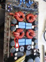
just had the real thing (in concert)
It’s just amazing, how loud a live orchestra really is…
It’s just „wow“ in every aspect.
pew-pew!
It’s just „wow“ in every aspect.
pew-pew!
Attachments

Hum increases when other monoblock is powered up.
- By sidn28790
- Tubes / Valves
- 7 Replies
Here is my situation. Pair of tube monoblocks. The monoblocks have 2 separate AC wall plugs separated by about 10 feet of 12gauge wire that reside on the same mains circuit.
When only monoblock A is powered (filaments and B+), the Vac at speaker A measures 0.8mV.
Then, while monoblock A is still powered, monoblock B is powered (filaments and B+). The Vac at speaker A connected to monoblock A increases to 1.2mV from 0.8mV.
This same increase of 0.4mV occurs if I reverse the process with monoblock A and B. So, it appears to me that there is a ground differential? Would it help if I added a 1ohm ground lift resistor between the chassis and earth ground. Other ideas?
Electrostatic bass panel question
- By milezone
- Planars & Exotics
- 32 Replies
Hi I am planning to build some electrostatic bass midbass panels which can operate from ~80hz to 1000hz. My goal is to emulate or improve upon the sound of Quad 57 bass midbass panels and to have some drivers which I can test against other types of drivers in various configurations in a modular capacity.
A couple notes and goals: I have owned various electrostats and panels including Quad 57s, Acoustat Xs with servo amps, KLH 9s, and extensively auditioned Soundlabs, other Quads, Apogee ribbons, etc. The Quad 57s which were restored by Wayne Piquet, had the best bass and mids of any speaker I have heard.
I have been experimenting with low mass 15" cones for this same application and I figure even a relatively thick mylar based electrostatic driver will be lower mass and more performative than any 15" woofer.
My goal is to basically replicate Peter Walker and Wayne Piquet's formula while optimizing for maximum SPL and headroom possible from an electrostatic panel. What thickness of mylar or similar, high or low modulus, conductive coating material, and stator gap/xmax is optimal for a bass midbass electrostatic driver of this nature?
Upgrading my old but trusted music server Acer Aspire One D270 to Windows 11 22H2
Hello
Looking at the D270 specs you may ask: Why struggle with a very old and outdated hardware instead of buying a decent laptop for ~400€?
Firstly
Well, the D270 has 3 USB 2 connections, HDMI, VGA and especially electrically separated connections for analog audio. The sound chip is superb; linear from 20Hz to 20KHz, which is essential for the development and measurements of my speakers. In addition, the RAM, hard drive, network card and battery are easily replaceable.
Secondly
Of course also my personal ambition to make the impossible possible.
Thirdly
I hesistate to throw away old, working hardware just like that.
This little beauty was running under Windows 7 - x86 for more than 10 years but Microsoft's (extended/prolonged) support for W7 definitely did end on Jan. 1st. 2023.
Ah, forget to mention: There only have been drivers for x86 although the CPU - Intel Atom N2600 - can handle a x64 OS. But there is no chance finding 64bit drivers!
To my surprise: A legally little modified Windows 11 ISO installed without any complains.
The embedded graphic chip, an Intel GMA3600, HDMI-Graphics/Audio, Bluetooth weren't recognized but I can live with that.
W11 installed a generic graphic driver with an unchangable native 1024x600 resolution but sharp and crispy to watch.
Sleep option is not displayed. Either you choose Hibernate or Shut Down. Also I can live with that. Why sleep while playing audio?
On W7 I often had a frozen audio player syndrom (not BSOD) with jriver and musicbee and had to stop/end/kill the corresponding process via task manager but not anymore. I never could figure out the reason.
Specs: Atom N2600, 4 GB RAM (2,93 GB usable) Graphics GMA3600, 1TB SSD.
Musicbee Wasapi exclusive to Phiree U2S to DXC2496-AES to Sony ST-BR-1070 6-Multichannel to 3-way loudspeaker.
Average CPU-load while playing audio - 7% at lowest CPU load with balanced power plan, 47°C CPU temperature, memory constantly at 79% (1GB system occupied)
Average latency ~ 500usec.
No glitches, drops, freezes or so.
5.1 Flacs I now stream over home network to the second up to date Dell-Laptop and via HDMI to a Denon receiver.
Additionally I installed a RAM-Disk (ImDisk) to use the remaining 1GB RAM and changed Windows temp environment variables and Edge's cache accordently to drive R:\.
Nils Frahm (All Melody) is flawlessly playing while writing this and I'm still in testing phase - looks very promising. Such a fulfilling result.
Have a nice weekend - and kind regards
P. S. I always did a full backup before doing any changes. That's, in such cases is essential. But obviously you know this.
Q: Citation2 Build-Huge Phase Inverter DC Balance Runaway
- By LinuksGuru
- Tubes / Valves
- 4 Replies
Hi,
I have built Citation 2 clone on a prototyping board, and now having strange problem with HUGE Schmitt phase inverter DC balance runaway. Prior building this amp I've done extensive simulation in LTSpice (incl. THD). Schematic with voltage and a photo of my stuff attached to the bottom of this post. Need to say, I made slight changes in Schmitt phase inverter and instead of several resistors and balancing potentiometer used 5W 12K + 5.1K resistors on both 12BY7A tubes. Anode resistors resistance were intentionally increased (17.1K instead of 14.5K / 15.4K if we assume potentiometer wiper is at 50% position) in order to lower excess anode current, and to compensate my slightly higher B+ voltage 470V instead of 455 of original design. In short - top V5 tube is in a runaway state, with only 240V anode voltage instead of 300, while bottom tube anode voltage is over 400V (which means very low anode current). Changing/swapping tubes have have similar effect - huge DC balance runaway of one of the tubes, it may be bottom or top, depends upon tube selection from available stock. Finally, found a pair which balanced more or less OK, with around 300V on both anodes. However, swapping them also leads to the same large DC imbalance. I checked board several times, schematic have been assembled correctly sure for 99%. Voltage on common cathode resistor is OK, and changes only +/- few volts. When phase inverter is DC balanced, I've got slightly different un-distorted RMS voltage from both tubes. Moreover, even when badly unbalanced, it still works with a big discrepancy in output voltage. So I assume phase inverter basically works, and the problem (may be) is a thermal runaway (may be gassy tubes?). One more caveat, feeding amp with 20Hz sine-wave leads to motorboating, but I don't think its a fault of phase inverter. Unfortunately, I don't have tube tester anymore to check my current stock of several RCA/Sylvania 12BY7A tubes.
There are no overheated resistors, had installed ones with excess power rating over those listed by HK in original schematic. 3 grid stoppers of 12BY7A are with ferrite beads. GNFB can be adjusted with potentiometer, and even turned on/off with jumper wire. Heater wires lifted on around 1.5cm from bottom PCB layer (may not be clearly visible on photo).
Anyone have any idea what may went wrong?
Thanks in advance for any help.
Attachments
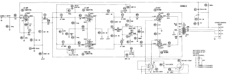
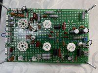
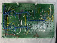
Load more
Projects by fanatics, for fanatics
Get answers and advice for everyone wanting to learn the art of audio.
Join the Community
507,637
Members
7,881,754
Messages