I'll be putting in the order for the remaining components to complete phase 1 of my ADC audio test kit so I thought I'd start using this thread as my blog as I go through.
The overall concept is to have a USB connected ADC that operates stereo balanced at 192KHz 32bit. I'm using a AK5572 board from nilita that includes opamp front ends, biasing and some power supplies. However I need to add some bits:
a) a case - a hammond metal one should be a good RFI resisting starting point.
b) a clock source - for phase 1 I will use a channel of my sig gen with the board setup with 50Ohm termination, then phase 2 I'll look at options for an internal clock.
c) a STM32 based discovery board - this will operate as the PCM/i2s to USB bridge - I have to write some code as part of this blog to get this to work - naturally if I can get this to work it's available for everyone to use as they see fit.
d) a couple of power supplies - initially in phase 1 I will use my bench power supply (SMPS so noisy) but in phase two I'll switch to a small internal linear supply. The ADC board will need +15, -15 and +5V and a second +5V for the STM board.
e) AC coupling components - I'll use 10uF MKP4 caps. I'm not interested in DC for this system. The maximum of 4Vpp inline with XLR.
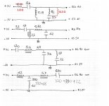
f) AC High voltage option - A simple 100Vpp or 400Vpp using a simple 9M+1M voltage divider ahead of the capacitors. Phase 1.5. This is for speaker or tube use and should give me 400Vpp.
The way the system will operate is that the ADC board will be configured as master with the MCLK connected to the sig gen at 24.576MHz (I may try higher if the Mac can cope). The ADC will then clock the PCM frame clock and bit clocks across into the STM discovery board where the STM will be configured as a slave.
Inside the STM, the system will be configured to detect the FIFO 1/2 full, causing an interrupt and that will then drive a DMA (no CPU used) to transfer the data from the FIFO into PSRAM ring buffer on the discovery board.
The STM will be configured to use OTG HS USB that's available on the discovery board. The USB OTG will declare itself as a USB Audio Class 2.0 (UAC2) device and the Mac will then see it as a USB Audio device like a microphone making it available to any app (Mac or Linux in a VM) such as REW etc. The important part here is the use of USB HighSpeed (480Mbit/sec) which the data rate requires and the use of UAC2 that supports the high data rate.
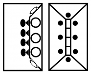
Internally the STM code will setup so that when a isochronous USB frame can be sent, the driver will DMA the data from the ring buffer in PSRAM directly into the USB output, in a diagram:
REW Application <-- MAC USB <------USB HighSpeed---- [STM USB] <--DMA-- Ring buffer <--DMA-- STM FIFO <- [GPIO PCM] <--- ADC
The first phase of this will be hard coded to 192KHz 32bit but as the ADC also offers control via i2c, I can also add soft control and then expose that control via the UAC2 control commands. This soft control will allow me to alter the rate and other configuration via REW etc. However a hard coded rate first will be enough.
This should all sit in a large steel case and as I progress I will keep an eye on noise etc but for now this should help keep noise down. If need be I'll address noise with additional shielding.
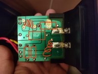
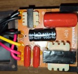
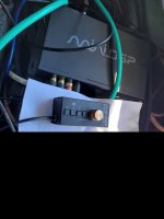
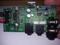
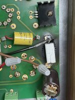
Testing the ADC board so far has been successful:


![20230320_094145[1].jpg](/community/data/attachments/1063/1063690-56f6933591fee495ff345169d554780e.jpg?hash=VvaTNZH-5J)


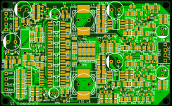
![2023-03-30 12_31_13-Xara Photo & Graphic Designer - [Untitled23 _].png](/community/data/attachments/1067/1067269-d72f9b0b48ec7511c5d5299d925d1e92.jpg?hash=1y-bC0jsdR)
