Kenwood Model 500 and Heathkit AA-151 Active Crossover Setup

Hi - Apologies up front. I'll put the essentials first. Details further on 🙂 - This is the plan:

Audio source ==> Kenwood Model 500 Integrated Pre Out ==> Nakamichi EC-200 Active Crossover ==>

==> Kenwood Power In (< 200Hz)
==> Heathkit AA-151 Aux In to Power Amp Section (> 200Hz)

(Speakers: Bozaks and Altecs)

Questions:
1) On the Heathkit, is it ok to run a wire directly from the auxiliary input to pin 8 of the 6AN8? (Volume is controlled at preamp/crossover)
2) Can the 6EU7 and 6AU6 tubes be pulled? And/or other parts of circuits be disconnected?
3) There's a 33K resistor and 470K resistor/33uf capacitor in parallel on the Auxiliary input - Is this necessary?
4) Do I need to be concerned about component compatibility (voltages, impedances, etc?)

Additional mods considered for long-term project:
- lower wall voltage to 117vac via bucking transformer
- replace power cord and add IEC receptacle that includes fuse, capacitor & switch (taking front power knob and lamp bulb out of circuit)
- rework output tube bias for individual (or pair) adjustment
- rework power supply filters - lower capacitance / add choke
- add switch/circuit for UL/Triode (Class A) operation

Did I miss anything? ;-)

Thanks in advance.
Jeff

https://ia804702.us.archive.org/6/i...lifier Assembly and Operation manual_text.pdf

Cardioid subs application

Hi,
I plan to build a bunch of compact subs for indoor and outdoor events. One idea was to use a pair of force cancelling 12" or 15" per cabinet. But I see Cardioid more and more often....
Looking for help on gaining some knowledge and applications cardioid and super cardioid subs. If the is a better forum for this unique subject, please let me know. Any links would be appreciated.

Cardioid subs:
When are they needed?
When are they NOT needed?
What are the tradeoffs to consider?
What are indications that cardioid type subs needs to be used?

Thanks!

Is it possible to get MQA digital output by adding an adapter board to a MQA DAC?

It's not difficult to understand the principle of MQA if we know the HDCD. Both of them compress the high definition music into standard low definition format. Without a MQA decoder, music is played normally in standard definition. However, with a full MQA decoder installed, it can output much higher sampling rate music up to 768KHz. The key difference is that the MQA was designed in a more commercial way. They issue licenses to music makers, online-music suppliers, device manufacturers and software developers for different levels of decoding. It is a full business ecosystem.

It's true that the MQA is not a 100% lossless format though they call it master quality. However, after carefully listening to the MQA music files that I downloaded from 2L on my MQA DACs, I found:
1. The sound quality of high sampling rate MQA music is better than the standard lossless 44.1/48KHz CD format.
2. The sound quality of the MQA music is very close to the high sampling rate original music file.

By considering MQA could be the only master quality music source we can access for our daily music listening experiences (for example, Tidal...) so far, I have to say I'm really happy with MQA. The only problem I'm having now is that the MQA is limited to the analog output of the MQA DAC itself, I can not play MQA music on my favorite DACs and my other digital music devices. That's really not very friendly to our audiophiles. So, here is the question:
Is it possible to get a full decoded MQA digital output by adding an adapter board to a MQA DAC?

The answer would be YES from the technical point of view, There is no difficulty to design an adapter board adding to an existing MQA DAC to tap off the fully decoded high sampling rate digital music signals from the DAC. By installing a HDMIpi and optional FifoPi to this adapter board, it will have a very high quality lower jitter MQA digital output signals. But now, we got another question: is it legal?

To be honest, I don't know the answer, but I can list some of the facts:
1. The adapter board itself has nothing to do with MQA so it has no business with MQA licence.
2. The MQA DACs do have the licence to decode MQA streams.
3. The end users own the MQA DAC, so they have the right to modify the hardware whatever they want.
4. The fully decoded digital music signal is no longer in MQA format.
5. There could be some limitations to the digital output when MQA issued a license to the DAC manufacturer, but the end users don't have any contract with MQA so the limitations may not apply to the end users.
6. There will be no such question if we don't play the MQA music on the DAC over the digital output.

I'm looking for suggestions and comments

Regards,
Ian


DigitalOutputAdapterPCB
by Ian, on Flickr

Some existing design for DIY active 2 ways with waveguide/ controlled directivity?

Hello,

I'm lurking on the Neumann KH150 or KH120 designs. I wonder if there would be around some DIY project for a similar size / performance, designed for DSP+active amplification.

I would look for good FR on and off axis, hence the waveguide (I have seen Augerpro ones). Low frequency would not be the priority, as a subwoofer would be considered. Reasonably priced: about 300-400€ max for drivers ?

I have seen the Directiva ASR R1 project, but to toy around the Purifi woofer looks way too expensive. And I like the idea that Neumann and many others achieve top performance with not so fancy drivers.

I have some experience with DSP and active amplification with my LX-Minis. But I don,t have the skills to design from ground up.

JMF

AUDIOLAB 8000C preamp

Dear,
My AUDIOLAB 8000C preamp burns its input fuse ( T1A 5x20mm ).
Because its transformer ( a Nuvotem Teo ) has its primary shorted.
Alas, I could not find the diagram for the 8000C.
So, impossible for me to know the characteristics of its transformer.
And especially the voltage at its secondary output.
In order to chise a new trasfo
Hence my question...
If One of You had :
- this diagram with this voltage value ?
- or knew these voltages ?
And if he agrees to tell me,
I would be infinitely grateful to him !!
My greetings from France,
Raymond

Attachments

  • Transfo Nuvotem Teo (R) .jpg
    Transfo Nuvotem Teo (R) .jpg
    232.4 KB · Views: 442

LU1014D Modulated Cascode

I have been looking at the LU1014D cascode behavior and found an interesting "modulated cascode" circuit that preserves triode behavior and expands the Vds (and power) range of the composite SIT-like device.

The LU1014D has triode-like (SIT) behavior but suffers from a 24V source-to-drain voltage range and limited power dissipation capability. These limitations can be overcome by cascoding the device as in the FirstWatt F3 and more recently the LuDEF (https://www.diyaudio.com/community/threads/ludef.369990/post-6588632) and the LuFo Amp (https://www.diyaudio.com/community/threads/lufo-amp-39w-se-class-a-from-28v-rail.372679/post-6665040). However, all of those cascode circuits result in pentode behavior of the resulting circuit.

The three columns of the image below show:
  1. The LU1014 degenerated by 0.73 ohms source resistor, showing triode behavior.
  2. The LU1014 cascode of the FirstWatt F3, showing pentode behavior because of the constant voltage cascode.
  3. The LU1014 with a "modulated cascode", showing triode behavior almost identical to the degenerated LU1014, but over a 10X expanded Vds range.
The black lines show 8 ohm load lines.

Attachments

  • lu1014-cascode-collage-2.jpg
    lu1014-cascode-collage-2.jpg
    432.7 KB · Views: 662

Monster Power HTS5100 dead...need help diagnosing

HTS-5100

It died the other day. No idea why.


EDIT:

It was a bad transformer on the power board.

Had done some testing on it based on a repair video I came across for another 5100. There was no proper voltage at the secondaries.

Once I got it off the board I confirmed the primary had no resistance at all and must've failed internally.

I replaced it with the smallest torroid I had lying around (120/2X15 80VA) that measured just short of 18V on the secondaries when I powered it up on the bench.

I hooked it up to the board mains inlet and wired the secondaries in parallel for a test. It fired right up.

I had to get creative and jack the board up with more stand offs so I could tuck the bigger tranny in underneath. Good to go.

If I had never found this forum and started messing around with DIY 10 years ago, I probably never would have been able to fix it. Thanks DIYAudio!

Input solid state relays - need your advice.

I hope you can help me to choose two relays:

1) a NO relay for switching on the signal source before the preamplifier for my home hi-end. The sound quality is of cause the most important, low external noise is second prize is third, other specification demands how I build the rest of the circuit.

2) A NC relay where the sound quality is of no concern, but the low external noise is most important, the voltage demands would be nice if they match the NO relay.

I know there is a total lack of information, but please ask, since I have nearly no idea on what info is needed to answer my question.

GZPA 1.4K-HCX protection issue

Amp came in from a friend, who said his local techs couldn't fix the issue. Amp goes in protect as soon as You apply any signal into the RCA input jack. Idles fine with no signal.

CF1 obviously has exploded badly for unknown reason to me at some point and now there are 2 film caps in series (doesn't seem right to me)?! I can't actually tell what are the CF1, CF2, CF3, CF4. Firstly I thought they are film caps, but pulling out CF4 has showed it is a resistor on my both testers ? Schematic from this amp, the pre-amp input section is attached. I don't know how or why has CF1 exploded as it's used in the output, not in the input and i pretty sure my friend does not use the output signal RCA jacks. So what is CF1 ?

Lifting one of the ends of R21 on the driver board (the 4.7ohm resistor used in the prot circuit) makes the amp produce clean output.
Fitting it back, in reference to the secondary ground, once the relay clicks in, some kind of a half sinewave pulses on R21 can be seen and amp starts restarting/recycling in a loop.
Obviously there is an issue with the protection circuit. Nothing is in short but I have my doubts on the MAX transistor as this have been my experience in the past.

I really would not want to pull out the driver board, is there anything else I can check and are issues with the blown CF1 and the protection somehow connected to each other ?

Attachments

  • 0.jpg
    0.jpg
    929.6 KB · Views: 178
  • 1.jpg
    1.jpg
    1.1 MB · Views: 170
  • 2.jpg
    2.jpg
    849.4 KB · Views: 159
  • 3.jpg
    3.jpg
    842.1 KB · Views: 141
  • 4.jpg
    4.jpg
    577.9 KB · Views: 168
  • 5.JPG
    5.JPG
    220 KB · Views: 185

Verry good CD transport

Im selling my Cambridge 840c cd player transport. I always used this for transport becose it was milles better than my audiomeca mephisto. The player is in like new condition with original packing, manual, remote and power cord. The price is low becose one chanel if you use this for cd player is about 40-50% lower in output volume. I already have buy this player with this defect from my good friend. I never trayed to solve or repair this defect. But for transport it is truly verry, verry good and top sounding. Price would be 200eu plus 19,80 euro shipping inside EU.

Attachments

  • IMG_20230318_085350.jpg
    IMG_20230318_085350.jpg
    479.9 KB · Views: 136
  • IMG_20230318_085346.jpg
    IMG_20230318_085346.jpg
    536.5 KB · Views: 142
  • IMG_20230318_085302.jpg
    IMG_20230318_085302.jpg
    368.2 KB · Views: 137
  • IMG_20230318_085404.jpg
    IMG_20230318_085404.jpg
    372.8 KB · Views: 136
  • IMG_20230318_085338.jpg
    IMG_20230318_085338.jpg
    428.1 KB · Views: 121
  • IMG_20230318_085310.jpg
    IMG_20230318_085310.jpg
    375.5 KB · Views: 133

Volume pot as input to LM386 Amp - "potentiometer" working (poorly), "rheostat" not at all

So here's the deal. I have an LM386-based chip amp, and I'm trying to put a volume pot before the input. When I wire it as shown in the top image, the pot works (e.g., it controls the volume), but the "maximum" output (e.g., pot turned to "10" or "zero resistance"), I only get about 1/5 the expected volume output. Now, my hunch is that my pot value (1k) is too low, so even when "dimed," the pot is basically bleeding off a lot of the signal to ground.

My question is this - in the second schematic (e.g., not grounding the third tap of the potentiometer, essentially using it as a rheostat), the pot doesn't control the volume at all (at least, I can't hear any difference). Why is that? Wouldn't dropping a 1k ohm resistor (e.g., when the pot is set to "zero" volume or "full resistance") in the signal path have some effect on volume? Or are the pickup and amplifier impedances just too high to have 1k make a discernible difference?

I will test out a 500k pot when I get a chance, but I'd like to know the theory behind what's happening here.

Thanks in advance.


IMG_0848.jpeg

Newbie wanting Bal/Vol control on an old TDA2003 bridged amp

As a first project in 20 years, I'm re-purposing an old Cana-Kit amplifier as a desktop amp to drive bookshelf speakers for mp3, phone, PC, etc. It has separate volume controls for each channel that I'd like to replace with Volume and Balance knobs. Will simply replacing the existing pots with Rod Elliot's "Better Balance Control" work OK for the level of quality we're already dealing with? The TDA2003 chips are often described as "good", but definitely not the audiophile level most folks here are striving for!

Attachments

Hello from East Texas

Hello to all and thank you for having me on this forum. I have been lurking for some time but am now just getting serious about DIY electronics. My past experience involves loudspeaker building, reviving old thrift store finds and repairing appliance boards but I am in no way a tech. As a lover of music though I have always owned a decent system. I own more recordings than electronics but I have prudently collected, and sold, quite a few over the years (I wish I had those Cornwalls and LaScallas back, not to mention that pair of Altec 200W tube amps-who knew?(I was young and that stuff was old. Parenthesis within parenthesis-I should probably break out Brown's)) and would like to learn how to do board level diagnostics and repairs. Though most times way over my head I am amazed by the knowledge, talent and generosity of the members here, not to mention the overall civility of discourse. Thank you for that. One problem I have is that I used to be rich and now I am poor. I used to be able to walk into a high-end audio store and actually walk out with something. My last experience however was less than satisfactory. I wanted American made components but the 3k$ tube integrated from Pennsylvania failed so many times I sat it on a shelf and plugged in an old Yamaha integrated (I'm really a Suzuki/Pops Yoshimura kinda' guy). After the Rotel 855 cd drawer failed I fixed it but when that fix failed I just took the cover off and made a top-loader out of it. East Texas in a nutshell. I rolled up those Kimber speaker wires and replaced them with a twisted pair of 10ga. magnet wire my motor winder gave me. The Magnepan 1.6's from the same buy however have been one of the best purchases I have ever made and I am hooked on the planar dipole sound. Long story short my electronics are old and failing, I am old and failing, but hell, I can still do better than that and if not I have a good excuse. I have been looking through here for a gutsy high-current solid state amp design to drive these Maggies and what I have found so far that seems to fit the bill is the Wolverine but I would welcome any suggestions for an amp that will actually drive a 2 ohm load, one that I can afford and one that can deliver the performance I am used to. I am an old bachelor so I don't care if it looks like an ice chest as long as it works. I figure if I recycle some of these transformers and use some of these nice nos parts on hand I can do it for a thousand bucks and I really don't want to sell my only child into slavery to buy an overpriced glitz box that cost less than the crate it's shipped in 'cause they know UPS will be lugging the thing back in and drop it on the floor from waist height. (Okay-that might be an exaggeration but with poverty comes bitterness and I have actual experience, perhaps because it was delivered to a machine shop). Enough proselytizing though. In my limited time here I have gained much and hope to actually be able to contribute in the future. You are some fine folks-keep up the good work.

Help with potentiometer on this schematic please

Hi - I am looking to replace faders on a mixing desk from the early 1980s. They are tired and worn. I'm new at looking at schematics and would really appreciate your help and expertise on replacements.

The current faders are 88mm long with 60mm fader movement and are 10K B (which I think is a linear fader). They have been swapped out at some point (tell tale signs of additional screw holes a few mms below the top screw hole).

I think the schematic suggests 5K B faders (but as a newbie I'm not sure if I am even looking at the correct part of the schematic!?). I have included a block channel diagram and the schematic for the channel (highlighting where I think the fader is located).

My questions are - am I on the right track? And if so, is it best to put in 5K B faders as per the schematic? Or are there advantages or draw backs with going with 10K B. Or is logarithmic (Audio) taper instead of the linear (B) fader? Any recommendations for faders? Thanks so much for help.

Attachments

  • Channel fader.jpg
    Channel fader.jpg
    133.3 KB · Views: 149
  • Block diagram of one channel.jpg
    Block diagram of one channel.jpg
    55.3 KB · Views: 122

Could someone help with a Box Build

Could someone help me with this box build.

The speaker: Ds18 Slc8s 200rms 8ich 4omh
The Box: length: 122cm width: 31.5cm hight: 15vm(as small as I possibly can)

The plan is to have the sub in the middle of the shelf of the table and for the Ports to be semetrical on both side, I have drawn a diagram for the box im the way I would like, the question would it work?

Don’t mind the ply it will be Sanded and prepped once everything is ready. Also using 18mm ply

Attachments

  • 7938D4A9-047D-4810-A319-82B832ECC2D5.jpeg
    7938D4A9-047D-4810-A319-82B832ECC2D5.jpeg
    1.1 MB · Views: 134
  • 86A15B50-FA31-4557-A77D-2F177C517ED9.jpeg
    86A15B50-FA31-4557-A77D-2F177C517ED9.jpeg
    915.8 KB · Views: 138

XLR ground - Pin, spring or both?

Hi all,

Just wondering what the normal practice is for connecting an XLR cable?

In particular how you connect the ground. Ignoring the shield for a moment, there are two ground connectors. There's the pin and there's usually a connection for the plug casing if it's metal.

What is considered good practice? Ignore the casing? Connect both?

Thank you.

Counterfeit ELNA Silmic II or genuine Elna ???

Hi,
I have been ordering ELNA Silmic II capacitors for years (from Mouser), and to date all the Silmic II that I have received have a brown jacket.

Recently I have been obliged to order a few Silmic II from another store and curiously the capacitors do not have a brown jacket but a Black/Gold jacket that I had never seen before: see the attached photos.

Do you know if they are counterfeit or genuine Elna Silmic II ???


Thank you very much for your reply,

  • Locked
For Sale MiniDSP SHD (Full Analog I/O Version)

ASKING PRICE: $650.00 payment by PayPal friends & family, postal money order or personal check. (Must clear my bank before shipment)

I am selling my 4 1/2 year old MiniDSP with full analog and digital I/O. Purchased new in November of 2018 directly from MiniDSP in HK. It's in very good condition and was removed from service just today when my new SHD Studio arrived. I no longer need analog I/O since I use digital crossovers and mastering ADC for balanced analog inputs.

This unit has fully up to date FW, Dirac3 and fully configured Roon ready streamer. Comes with original remote control, IEC power cable, USB control/Audio cable, and the optional rack mounting ears. It does not come with a UMIK-1 or 2 mic which is required to do Dirac calibration. (My plug-ins will not be useful to the next user.) I can provide a brand new UMIK-1 mic separately if needed.

In very good condition, the OLED display has some burn in as this is an original 1st generation SHD and FW screen auto-off option did not arrive for several years.

Top.jpg


Front.jpg


Rear.jpg


Accessories.jpg

locking problems with CD transport

Hello
Just for fun, I decided to use my shigaclone cd transport to make comparaisons with files on computer. In the time I had a homemade dac which worked correctly with this Shiga. It used a CS8416 receiver. Now I have a DCS dac and it doesn't want to lock with the cd transport . If I use the transport connected in my Audio gd interface DI-20 connected to the DCS it works but I sometimes hear cracking noise like if I played a LP.
The output of the cd transport is 0.5V. As you can see, the square waves taken at the output of the transport at the end of a 1m coax are quite good. With my frequency counter connected to the output of the cd transport I read 1.79 MHz. What could be the problem ? Thanks.
20230421_120922.jpg
20230421_124508.jpg

Help please. Low volume Roksan caspian mk 1

Hello, I have an issue where im getting low volume on my Roksan Amp. I have bassically stripped it down as i want to restore it .Before i get the spray cans out id really like to get the amp working properly.As i really have no clue,where would i start looking.I have a multimeter and i can solder ok .


Thanks in advance

Mick

Attachments

  • 20230422_112614.jpg
    20230422_112614.jpg
    620 KB · Views: 200

Behringer EP4000 for H/T

I think I'm going crazy. I keep throwing money at this project and getting nowhere. Hoping someone can help.
I have 2-15" subs. Trying to power with the ep4000. I'm using the art clean pro box in line. The lights on the amp seem to be working good. I can go all the way to clipping and get almost no sound from the speakers, just a lot of heat. Not sure what I'm doing wrong. Any help on this would be extremely appreciated.

Yamaha TSR-7850
Art clean box pro
Behringer ultra gain pro mic 2200
MVX VSW154 V2 x2

GNF / LNF resistor values and general tube topology Q....

1st, I have added 2 toggle switches for R15 (LNF) and R16 (GNF) in the schematic below.

I think may be I would have liked a stepped attenuator's instead, (4 step at most if it exists) so I could go from the default value to off (leaving 1 set of resistors disconnected from stepped attenuator)
A low(er) volumes, I love the sound with zero feedback, for me its not even a close call. BUT zero feedback clips quicker (as volume goes up) for me...
When we are entertaining a small group all the way to having the house is loaded with guests, I could add in FB depending on how loud folks want the music...

Im unsure of how to set up an AC measurement on the feedback.
For example at C8, (what input test voltage should be, what the actual volume knob should be dialed to and lastly how the cathode voltage on the first 12AT7 might interfere..
I was thinking measure the V after C6 with LFB on and off and guess the difference was what was actually going through C8..
Then do same test with GFB...
Feeling like Im outside of my comfort zone... and didnt want to pull the amp out of service (enjoying SE again!)
figured I should ask the guru's!

With the schematic below (and a 4 step attenuator if it exists)
Im unsure of what the values should be for the 3 resistors on either the GFB/LFB circuit should be...
R15 @ 330k is by far the lowest resistance (Most FB) I would ever want, so I thought in series I could add some arbitrary values, call it value 1, then on the second step more resistance Value2 , 3rd even more and finally the 4th would be infinite resistance (no resistor).
Same for R16 and the GNF, would never want more fb., so would only like to add resistance ...

Anyone have a gut feel for what the R values should be (both GNF and LNF) ?

The 2nd Q, does anyone know the topology of of the QSN7 (cathode to plate) above.. is it cascode / cascade / other ?
Im getting reasonably good at understanding basic tube circuits, but this has me looking for a better understanding.
My take is the upper QSN7 is the voltage amplification while the lower adds more current, Am I close ?
Id love to find a tutorial showing the sine wave's phasing and realitve levels for each cathode, grid and plate ..

Attachments

  • gnf-topo.jpg
    gnf-topo.jpg
    306 KB · Views: 73

Wharfedale speaker 3XP and XP2 tweeters

Due to hearing problems (being almost deaf now due to working on jet fighters in the RAF in the 1960s) and having to listen to my Hi-Fi through hearing aids I have gone back to 1970s speakers which seem to sound better to me.
I have two sets of Wharfedale speakers one being Glendale 3XP and the other being Glendale XP2. Both sets fully working.
I prefer the treble sound from the 3XP as it is less harsh than that of the XP2 but I prefer the bass from the XP2 as that in the 3XP seems a bit one note and not as deep as the XP2. Both speakers have the same sized cabinets and I gather the mid and bass units are the same in both.
Can I therefore simply transfer the tweeters from the 3XPs to the XP2s using the XP2 crossovers as fitted or would that cause a problem?
Advice please.
Geoff.

Flags are back / new member information section

Pre-migration to XenForo, a flag next to each members name helped us all to see what an amazing, very much global community diyAudio is. A melting pot of cultures from around the world who all share the same fanatical passion for audio.

These have now been returned, along with a tidied up member information section that is to the left (desktop/tablet) or top (mobile) of every post. Changes as follows:
  1. The dropdown/dropup button has been removed
  2. 5 pieces of information are now shown on desktop/tablet (member title, membership upgrade status, join year, flag, website). The member's typed location details (if entered) appearing when hovering over the flag.
  3. Join year and website are not shown on mobile to save space
  4. Website has "www." stripped from it to reduce clutter
  5. The old "donation star" has been replaced with what feels like a more descriptive icon - a shield. This signifies the member has helped to protect diyAudio by contributing to its operating costs this year.
  6. The green online indicator over the avatar has been removed as it cluttered things up and didn't look great. Same with the OP icon which is not nearly as important on our site with long threads as other sites. Either might return in the future with a nicer presentation.
If you experience any issues with the new layout please post here or send an email to the helpdesk at contact@diyaudio.com.

For Sale Korg Nutube B1 Preamplifier

Hi, I have a mostly stock Korg Nature B1 Preamp. I've added isolation feet, board mounts and added mass/covered slots on the inner side of lid to successfully eliminate microphonics. I was using this with an Aleph-J and sounded great. I'm now using a tube amp and find the tube on tube action a little too much for my taste. Functions perfect, looks perfect and sounds great. Comes with stock 24v/0.5A outboard SMPS. Don't hesitate if you have any questions! Asking $300

IMG_0573.jpeg
IMG_0569.jpeg
IMG_0570.jpeg
IMG_0571.jpeg
IMG_0572.jpeg
IMG_0574.jpeg

Not to expensive SMPS with a few % bad reviews. Exchange Mosfets in advance?

Hey people,

I've got an adjustable SMPS with max. 48V/ 10A, bought at Amazon, brand/ model is "HJS-480-0-48". I want to use it as power supply for a class-D amp in stereo BTL mode driving two 6.5" Midwoofers (atm. I've got 5.25" midwoofers driven by LM3886 chipamps which are really loud enough (max. 60%, never tried more) but I just want to move more air). I think, I'd never really torture the PSU, but I've read a (or maybe two) review(s) where this specific SMPS broke down when driven near the max. current.

As I made a few little modifications (bigger & slower fan, internal mains power connection with on/off-switch instead of screw-terminal, exchanged a few electrolytics which measured below nominal capacitance) I took a look at the mosfets which are STW20NB50 with a continous Id of 20A @ 25°C. Should be OK ... or do those seem to be more than they are?

Anyway, I do not have this type of mosfet in my box, but I've got some which might fit, and which are 100% original.

So my first question, could I replace the STW20NB50 with IRFP460 or STW26NM60N?
My 2nd question, if the 1st one is a "yes": Never change a running system, or better be safe than sorry 😉 ?

best regards
Jochen

Does a bigger recess affect the sound?

I am currently building a pair of speakers where the diameter of the woofer is 177 mm (6,97 inches) and the thickness is 4mm (0,16 inches).
At some point in the future, I will probably upgrade to an other driver with a diamenter of 183 mm (7,20 inches) and a thickness of 6 mm (0,24) inches.

Since I know about the upgrade already, I am planning to make the big (183 & 6mm) recess from the start. To make the smaller driver flush with the baffle and look better, I am going to 3D print an "adaptor" that takes up the remaining space in the diameter and depth.

Would the above plan be likely to affect the sound? Or is it a reasonable plan?
Sorry for the probably stupid question, but I'm not sure whether flush mounting is only about aesthetics or whether it affects the sound.


Thanks already

The SIT-3X Amplifier

The birth of SIT-3X: Everything started in the at post #119 https://www.diyaudio.com/forums/pas...-mu-follower-amplifier-build-post6161792.html, in a thread which was originally oriented towards the FirstWatt SIT-2 mu-follower circuit. Along the way, I analyzed the circuit of the FirstWatt SIT-3 and discovered a simple circuit change that performs harmonic cancellation, including odd harmonics! After more analysis, simulations, and bench testing, I saw the posssibility of a very low distortion amplifier with no global feedback. Here are the expected specifications:

  • Output Stage: Source Follower Tokin 2SK182ES SIT + IXYS IXTN40P50 PFET.
  • Choice of front-end stages:
    • Buffered, folded cascode FE with no feedback loop
    • XA25 style FE: requires feedback from FEOut to obtain low impedance output.
  • No global feedback.
  • 25W-50W power output
  • Adjustable cancellation of both even and odd harmonics.
  • THD at 1 Watt, 1kHz into 8 Ohms < 0.02%
  • THD at 25 Watts, 1kHz into 8 Ohms < 0.5%
The "Sit Measurements Mu Follower Amplifier Build" provides important background leading to amplifer design presented here. Since forum members are requesting that the design be completed, I decided it was time for start this thread. In my next few posts I will present the current designs for the output stage, folded-cascode FE, and XA25-style FE. There are still issues to be resolved and parameters to be "tuned", but I think that PCB layout can start.

Frankenstein-ing a commercial sub

I could fit the unltimax 8" after I gut out the T3. The dimensions are right, even after bracing and lining it.
How would it cause the stock PR to behave? **** poor I imagine. I think it might be better to change it or at least cover the hole. https://www.parts-express.com/Dayto...-Subwoofer-2-Ohms-Per-Coil-295-508?quantity=1

Does an f3 of 43hz sound right in such a small sealed cube, of 0.8 CF in the PE site. When I measured I think it was 10" , no more than 11" cubed.

It sounds VVG as it is. But what fun is that? I can always turn it around later anyhow. The 8" underneath looks the part and sounds, but its pretty poor job with too much power (in other words not a lot).

Attachments

  • 20230422_004330[6434].jpg
    20230422_004330[6434].jpg
    305.4 KB · Views: 93

SPACE class A headphone amplifier: in pursuit of true dynamics

From my point of view, one of the most significant drawbacks of listening to recorded music at home is the compression of the dynamic range, which results in insufficient "contrast" compared to what is heard at a live symphonic concert. The equipment may play smoothly, but listening to it can be boring. Live sound is not always smooth, and sometimes it requires some effort to perceive, but it certainly cannot be called boring.
The changes in volume in a concert hall can take your breath away.
Can realistic sound like this be achieved with headphones?

After lengthy experiments with various amplifier schemes and PCB topologies, I believe I have figured out how to create a device that does not "steal" dynamics.
The main points are as follows:
1. It must be a solid-state amplifier because only this type can provide low output impedance and low harmonic and intermodulation distortion.
2. The amplifier circuit should operate in class A with a large and almost constant bias current, excluding modulation of the device's power consumption by the musical signal.
3. High output power is not required because typical headphones have a sensitivity of about 100dB/1mW.
4. High dynamic linearity can be achieved with a topology that makes the amplifier immune to external high-frequency electromagnetic interference, both at the input and output and in the power supply circuits. This is often neglected, but over the past 30 years, the intensity of external electromagnetic fields in large cities and the pollution of the power grid has increased thousands of times (cell phones, Wi-Fi, SMPS, energy-saving light bulbs, etc.). Simple solutions that worked well in old devices no longer work.
In my device, I used a custom CNC-milled aluminum enclosure. If you put a cell phone inside such an enclosure and call it, the call will not go through because the enclosure is capable of completely blocking incoming and outgoing radio waves. Ordinary enclosures consisting of separate panels connected by screws do not have this ability.

The listening experience of the device revealed the following distinguishing features:
  • At first, the sound may seem uncomfortable, and adaptation is required.
  • After adaptation, the amplifier encourages increasing the volume more and more. The most exciting sound, in my opinion, is achieved at SPL above 90dB.

Tech specs:
Input connector type: 2xRCA unbalanced
Output connector type: stereo 6.5 mm
Input impedance: 10 kOhm
Output impedance: <0.8 Ohm
Frequency response: 5-30000 Hz (-3db)
Gain: 10.8 dB
Channel imbalance: <0.2dB
Max output power: 200mW at 32 Ohm

spac-akg812-2.jpginside2.jpgb-w.jpgspace-audeze.pngspace-inside2.pngthd918hz.jpg
  • Like
Reactions: freddi

For Sale The big cap blowout

Hi guys and gals. For sale are some mostly nos a few lightly used for testing in a circuit capacitors for sale.

8-ROE 15,000@40v
10- BHC 15,000@63v
20-Kemet 15,000@63v
13-Kemet 10,000@63v
3-Vishay BC 15000@60v
4-Cornell Dubliner 18000@70v
2-Vishay BC 15,000@63v
4-Epcos 15,000@63v

$20 each plus shipping

I will be posting more 33,000mf capacitors later. Cheers.

Attachments

  • IMG_4359.jpeg
    IMG_4359.jpeg
    241.2 KB · Views: 95
  • IMG_4360.jpeg
    IMG_4360.jpeg
    256.4 KB · Views: 96
  • IMG_4361.jpeg
    IMG_4361.jpeg
    258 KB · Views: 96
  • IMG_4362.jpeg
    IMG_4362.jpeg
    257.5 KB · Views: 91
  • IMG_4363.jpeg
    IMG_4363.jpeg
    280.3 KB · Views: 89
  • IMG_4364.jpeg
    IMG_4364.jpeg
    302.3 KB · Views: 88
  • IMG_4365.jpeg
    IMG_4365.jpeg
    568 KB · Views: 87
  • IMG_4366.jpeg
    IMG_4366.jpeg
    284.4 KB · Views: 77
  • IMG_4367.jpeg
    IMG_4367.jpeg
    271.3 KB · Views: 84
  • IMG_4368.jpeg
    IMG_4368.jpeg
    357.1 KB · Views: 94
  • IMG_4369.jpeg
    IMG_4369.jpeg
    328.4 KB · Views: 89

Greenvalve 10y into 801a

Hi all,

This summer I'll be plunging into the greenvalve design with 10y driving 801a, through hammond interstages and SMPS power supply.

I'll follow the schematic but will use 4 rod coleman regulators for the filaments.

This is my first DHT build, and how bias works is still beyond me.

What would you recommend? Filament bias on 10y, maybe with SIC diodes, and how many volts? And what to do with the output stage?

Any pointers on filament topology and values for this circuit are most welcome!

Cheers,
Simon

Attachments

  • greenvalve-luddite-marcin1.jpg
    greenvalve-luddite-marcin1.jpg
    157.1 KB · Views: 1,058

For Sale Various Jupiter Capacitors

Selling my Jupiter capacitors, most are barely used and there are two of each. eBay links are below and am open to sensible offers;

Pick up in Glasgow (UK), or will ship worldwide

Selling my Jupiter capacitors, most are barely used and there are two of each. Links are below and am open to sensible offers;

Jupiter HT Beeswax Paper 2.2uf @ 600Vdc

https://www.ebay.co.uk/itm/26620935...jmrlHJpsrT0koav1gHs8s1T6SH|tkp:Bk9SR-jw-ZPsYQ

Jupiter HT Beeswax Paper 3.3uf @ 600Vdc

https://www.ebay.co.uk/itm/26620932...EbpK3oTPnA36IbFmJkhaMbCQ==|tkp:Bk9SR4Sn7ZPsYQ

Jupiter Copper Foil 2,2uf @ 100Vdc

https://www.ebay.co.uk/itm/26620932...xvKpNcL2G4HsJgUG61QXlARg==|tkp:Bk9SR4Sn7ZPsYQ

Also selling my Yaqin SD CD3 upgraded qwith Mundorf Silver/Gold in Oil Capacitors

https://www.ebay.co.uk/itm/26620935...NIOUeIB15t6S1BwYG89ihs+g==|tkp:Bk9SR9LR_pPsYQ

The New Vifa Tower Kit as shown on MurphyBlaster Productions web site

I have all the parts (except lumber) to build "The New Vifa Tower" as shown on MurphyBlaster Productions website.
Current status of the crossover parts - most of them are already soldered together on the back of a board that the tweeters are mounted on.
You might have to rework these, and the leads are getting pretty short, so it might not be easy.
Woofers are mounted in the lids of blue 5 gal buckets from Lowes. i had a hare brained scheme of making something where the tweeter board was transported INSIDE the same bucket the woofer is mounted on. Upon arrival at "the cabin" the tweeter board would be set on a table top and woofer would remain in a bucket on the floor, or possibly have some type of stand that would hold the bucket in a horizontal position on the table, but that never materialized...

Okay, so the above paragraph is the Bad news,
Good news:
(3) VIFA M21WO-39 woofers, MADE in Denmark, used only a couple minutes, for testing.
(3) VIFA D25AG-35-06 tweeters, MADE in Denmark, used only a couple minutes for testing.
Reason for QTY (3) drivers was originally for if i wanted two Vifa Towers plus one matching Center channel made from the same products, but never happened.
(2) OEM metal grills for the woofers, as you might see in car audio, with plastic trim rings, made precisely for this woofer, by VIFA.
(2) OEM metal grills for the tweeters, same story.

I am willing to let these go at a loss. i have at least $300 into it, and you can have them for ANY kind of OFFER. maybe if you pay shipping and give me a box of donuts?!

Transistor Base Collector and Emitter have the same voltage

I have a Hybrid Mk2 Active Powered speaker

I have 39v AC that hits a bridge rectifer , this converts the current to 52v DC.
This DC flows into the Collector pin on the Transisters (2x A1941 and 2x c5198)
The DC on the Collector, Base and Emitter is 52v

Does that mean my transistors are blown because all 4 give the same reading accross all 3 pins

Also the Relay on the Board has 24v on the N/C and on the N/O , is that suppose to be that way as my understanding of the relay is that once the poll moves from N/O to N/C the current is on N/C
Shouldnt N/O become 0volts
Its a srd-24vdc-sl-a relay and its not clicking nut the voltage at N/O is 24v which is correct so im really lost.

Redneck ZM DEFiSIT/DEF biasing

to save you from ghost chasing and give you some more time for quality staring at goats, which is much more beneficial for state of mind

at least I'm finding it that way

disclaimer - both DC offset and Iq stability are depending of hefty heatsinking, rail variance ( mains fluctuation) and hope that SIT in case is not having hungry gate

here is case one - SIT Ugs lower in number than P channel Mosfet Ugs, so SIT gate is higher than Mos gate, voltage vise

reckon that 2V5 voltage reference is covering most possible cases; if more is needed, there are ways for that too, easy to increase

it is important to use voltage reference being stable from low Iq; from memory shown one is stable from 10uA upwards

circuit is tested and proven

picture self explanatory; THF51 as example, applicable for pretty much any depletion device up, being similar in behavior

Attachments

  • DEF OS stage THF51 biasing simplification  REF ZENER.png
    DEF OS stage THF51 biasing simplification REF ZENER.png
    13.5 KB · Views: 1,154

Round 2 of attempt to refurb Philips GA 222 turntable - speed issue

After giving up for a couple years, I've again decided to see if I can save the old girl. The problem: the platter spins super fast. I was told here originally to check for bad capacitors. This week, I took everything apart and inspected two caps in the speed circuit that might be involved. They both look fine, but I understand they can just crap out with age. I figured I'd just try and replace both, and see what happens, but I'm having a hard time figuring out replacements. I'm attaching the schematic, and info on the caps in question. To further complicate things, someone suggested recently that it could be a governor failing in the DC motor. That's a whole new wrinkle, and I have no idea how I'd even deal with that or test for it. The dead caps seem to make more sense. Anyone have any thoughts or suggestions? BTW, I'm a novice, not an experienced electronics tinkerer.

c731 and c729 caps on turntable-hilites.jpg


capacitor for turntable.JPG

Need 8 pairs of 2SK1058 & 2SJ162 for Hafler 9505

I need new output transistors for my Hafler 9505 amp. Looking online it seems like no one has 2SK1058 & 2SJ162 in stock. Well, every place expect a store called Jims Audio out of Hong Kong.

Searching this site I found Exicon ECX10P20 and ECX10N20 mosfets are drop in replacements. Issue I have is the Exicon's are ~$7 a piece and I need 8 matched pairs so I would have to purchase a lot more than I need. The pairs from Jims Audio are supposed to be matched and come out to ~$8 a transistor.

I'm looking to hear from people that have purchased from Jims Audio to see if they think the site is selling authentic parts. And also to see if anyone here has matched pairs of either types of mosfets mentioned they're willing to part with.

Free Starkrimson Mono Bare PCBs

Hello,

I have some Starkrimson Mono Amp Module bare PCBs that I will give away for free, you just have to cover the cost of shipping.

Please note that to receive the BOM for these boards you need to sign a non-disclosure agreement (NDA).

Since I am giving these away for free, I request that all people who receive them and end up making amps write a review of the amp modules on the website.

If you are interested please contact me though this link only. Do no send me private messages though the forum.

First come first serve, there is a limited quantity available.

Regards;
Leo

Frequency response measurement order of operations

So I'm new to the game of speaker building, I tried an MTM design with Dayton Audio drivers using their in house frequency response measurements, in classic style, I built before I read. I'm going back to the drawing board for MKII design, what I need to know is order of operations. So I have the driver's, once the cabinet is assembled would I then take FR's of each driver to load in to vituixcad to design the crossover? As I now believe the ones supplied Dayton audio obviously wouldn't match the cabinet I've built. Also, would you measure both Mids together as single response graph? And when measuring, would you just discount the tweeter to measure the mids and vice versa for the tweeters? I'm sure this has been discussed before but there's some many posts at this point, the digging wearing me down.
  • Like
Reactions: GM

For Sale Amorphous Cores Set for 50W Audio Output Transformer Vacuum Tube PP Amplifier

Hi! I have for sale: 2 full sets (8 x O-loops, 16 C-halves) of amorphous transformer cores for audio output push-pull vacuum tube amplifiers 40-50W (EL34, KT88, 6550, etc.).
Enough to build 2 output transformers. Cores must be stacked to get required cross-section area.


Max flux density B for amorphous material is 1.56T. Excellent cut quality, without dents and chips.
Dimensions on 3rd photo. Manufactured in China.
May be suitable also for SE amplifier if finished transformer assembled with an air gap.
149.95 Euro + shipping.
Shipping only to EU countries.

Attachments

  • Photo 23-04-18 21-46-34 7338.jpg
    Photo 23-04-18 21-46-34 7338.jpg
    602 KB · Views: 99
  • Photo 23-04-18 21-46-51 7339.jpg
    Photo 23-04-18 21-46-51 7339.jpg
    606.8 KB · Views: 102
  • Screenshot at 2023-04-18 21-54-52.png
    Screenshot at 2023-04-18 21-54-52.png
    86 KB · Views: 96

For Sale Amorphous Cores Set for 25W Audio Output Transformer Vacuum Tube Amplifier

Hi! I have for sale: 2 full sets (4 x O-loops, 8 C-halves) of amorphous transformer cores for audio output push-pull vacuum tube amplifiers 20-25W (EL84, 6P14P, etc.).
Enough to build 2 output transformers.


Max flux density B for amorphous material is 1.56T. Excellent cut quality, without dents and chips.
Dimensions on 3rd photo. Manufactured in China.
May be suitable also for SE amplifier if finished transformer assembled with an air gap.
79.95 Euro + shipping.
Shipping only to EU countries.

Attachments

  • Photo 23-04-18 21-27-05 7334.jpg
    Photo 23-04-18 21-27-05 7334.jpg
    595.2 KB · Views: 89
  • Photo 23-04-18 21-34-15 7335.jpg
    Photo 23-04-18 21-34-15 7335.jpg
    619.9 KB · Views: 96
  • Screenshot at 2023-04-18 21-54-26.png
    Screenshot at 2023-04-18 21-54-26.png
    74.7 KB · Views: 99
  • Like
Reactions: ranshdow

NAD 3020 inspired home made amp

First of all: I didn’t really noticed this forum before. I think I have stumbled across some threads in my research to do this project. Now that I have registered, I think it is nice to share my attempts to recreate a NAD 3020 (or actually 3120). So here it is, hope you like it! I certainly enjoyed creating it (and continue to enjoy it when listening to it)!

Disclaimer: just as I was about to start this thread I noticed that other people have played with the idea to recreate this fantastic amp themselves. So yeah there might indeed be a sect going on right here 😉, I hope this doesn't bother anybody too much then. I did this project as a big learning thing and just for fun. Didn't really study electronics so at times it was a bit of a learning curve and I am still figuring things out. The amp is working perfectly fine though but if there are things that are odd in my attempts and design, please let me know!

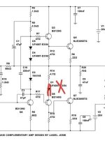
The circuit design of the amp is – of course – not mine but from NAD. So credits to them for creating this lovely sounding historic piece of equipment. I recreated the boards myself to fit my needs (see below) and added some features to it (and left some out). I tried to keep it as close to the original as possible but ended up creating a simpler version more like a 3120 (or even more simple with just a volume knob).
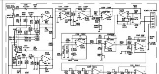
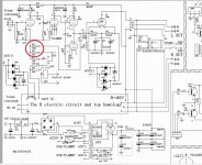
Schematics
My attempts started last year when I got the idea to build my own amp. Just to see how far I can get and if I could – in theory – end up with a fully working device. A bonus would be that it sounded half decent and didn’t start a house fire… 😊

Searching for a suitable candidate I found that the design of the NAD 3020 would suit my needs. I wanted a proven concept, not too complicated and not too powerful. Furthermore, it had a nice small form factor and of course had somewhat of a reputation.

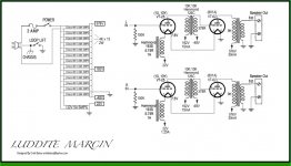
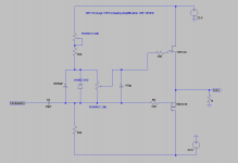
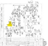
First I recreated the schematics in KiCAD. I’ve used the schematics from the 3020B as a reference and worked from there. The main difference is the lack of balance control, mono buttons and muting. I also used more foil based capacitors replacing some of the electrolytic caps in the signal paths.
1676503456662.png
1676503279054.png

The lack of a proper input selection switch eventually made me design a digital logic board with LED’s and relay switches. A microchip PIC16F628 does the switching but also acts as a power-on delay and controls the speaker outputs for muting and protection. The protection that has been integrated is DC detection, AC dropout (acts as a soft power-down) and of course the delayed power-on. The soft clipping is of course also integrated into the amp.
1676503387235.png

I incorporated some extra power supplies for the digital 24V and 5V rails (needed for the relays and PIC). These are all relatively low powered and taken from the main positive power-supply, so the digital signals are separated from the pre-amp and phono stage.
1676503305257.png

PCB designs
The design of the PCB’s took some time to develop. I wanted to etch these myself and therefore used a maximum PCB size of 100x160mm (most boards are a little smaller in length). All boards are single sided and I have used as little jumpers as possible.

The design resulted in a power-amp PCB per channel, one PCB for the phono and preamp stage and one PCB for the power-supply. The last board I etched was the logic board and input selection board. They fit nicely together onto one 100x160 board. In the end I added a separate fuse-holder board and speaker inductor board.
1676504340493.png

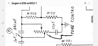
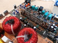
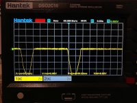
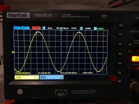
I’ve taken special care to route all ground planes (if any) and ground wires back to a single point. Took some time to carefully prevent ground-loops when interconnecting the boards. As far as I can tell it all worked out as there are no hums, noises or anything like that. There were some oscillations going on in the phono-stage so I ended up tweaking that somewhat and making it look more like the 3020i version of the amp. I added some extra capacitance around the transistors but I might look into that a bit deeper somewhere in the future.

Parts
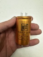
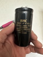
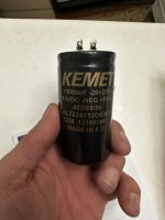
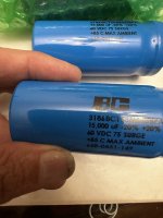
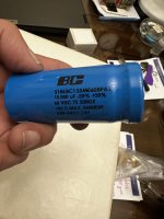
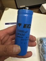
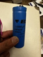
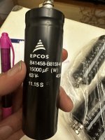
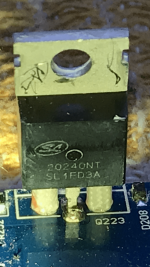
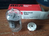
Most parts were readily available. I mostly used Elna Silmics and replaced some elco's with MP caps. I have found a source for most transistors (especially the SD669 and SB649 are a bit harder to find). The power transistors are still readily available from Mouser so I kept those into the design as I just really like these shiny metal things if only for the looks 😊

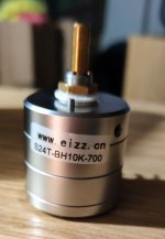
The hardest part was to find fitting balance and volume control pots with the center tab for loudness. In the end I ditched the tone and loudness control pots and figured I could do without since I never use those anyway. This actually made me decide I could just go for a 3120 version. The volume control is a nice quality pot from Alps (which by itself costs a small fortune).

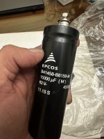
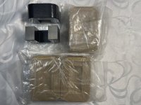
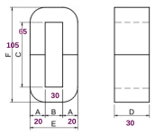
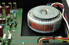
I used two toroidal transformers (2x24VAC for the poweramp and 2x30VAC for the pre-amp). The smaller pre-amp transformer has a bit more headroom for the required output voltages. The powersupply does run a bit hotter than the original design because of the bigger voltage drops, but nothing out of the ordinary. Just added a suitable heatsink and we’re good to go! The result is a nicely separated powersupply for the pre-amp and poweramp. Wires are all helutherm 145 with JST connectors in various shapes and sizes. Gives it a nice quality feel. I soldered all the signal wires.
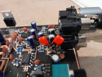
1676504966808.png

Build
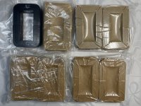
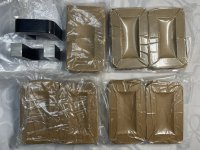
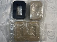
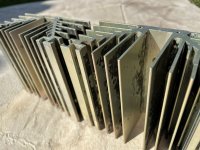
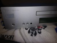
Now that everything is there, it was time to find some nice case to put it all in. I did a small CAD drawing and decided that it could (and should) fit into a 80mm high case. I’ve used a cabinet from an Italian supplier (MODU Pesante). I’ve got an oversized heatsink that goes right into the middle of the amp. The poweramp PCB’s are mounted with some L-shaped aluminum pieces to the heatsink so that it comes out in one big module if unscrewed from the bottom.

I’ve finished the design with amber LED’s and some retro push buttons because why not... The logic board is nicely positioned behind the LED’s with male connectors on the PCB, precisely aligned with the front. This was a bit of a puzzle on the PCB design. But pushing these buttons gives me the rewarding sound of multiple clicking relays and that is just fantastic as it sort of makes the thing 'modern' 👍

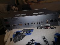
In the end I decided I will just skip the pre-amp output on the case and wire the pre-amp directly to the power-amp internally. I might add these typical NAD 3020 jumpers to the back in the future to play around with. The connections are there on the PCB (main in / lab in / pre-out).

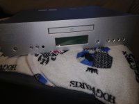
So here is the end result!
1676504824553.jpeg
1676504868733.jpeg
1676504768209.jpeg
1676506525052.jpeg

All in all it was (and still is) great fun. Hope you like it!

P.s. I’m still contemplating if I should upgrade the PCB’s with prototype boards from PCBway or similar but it’s not cheap and you end up with 5 copies and I kinda like the idea that I’ve built the entire thing from scratch (including the boards). Let me know what you think!

Update:
As per request I've included the PDF files and BOM. I do a separate post about the software, that's a whole new story

Update 2:

As of writing all of this, I was trying to panelize the boards and correct some design issues I had in my own etched boards. Just noticed there were some small errors in previous PDF's (there was a couple of rotated footprints). I've updated the PDF files to correct this. Furthermore, there was some interest in the schematics as well, I've included the KiCAD schematics, see attachments.

Attachments

Proton AM-656 schematics

Hi,

my ugly but beloved Proton AM-656 is not working anymore. I suspect that the power on circuit has some problems.

Unfortunately the amp has a very complex power supply section, with three transformers and an indecent wiring style, so it's really difficult to perform a reverse engineering analysis.

Where can I find the service manual, or at least the schematics?

Many thanks in advance to everyone

REAL Novar sockets inside ;<)

Received shipment 100pcs of Big base 9 pin equipped w/ 1.0mm pin sockets ... Am ecstatic to report that they are CORRECT!
First trial fit into 12GT5 was a bit tight- but relaxed to normal after 3 insertion / removals.
To abbreviate design thesis- install Compactron pin sockets in Magnoval bases- The End...

To give credit where it's due- 'smoking amp' gave me the idea, I just followed thru and made it happen on the production side-
Pic #2 shows silver pin Magnoval (1.2mm) socket next gold pin (1.0mm) Novar hybrid. To accomplish this would seem easy, but there were hurdles-

Background:
https://www.diyaudio.com/community/threads/novar-dilemma-b9e-vs-b9d.376483/
https://www.diyaudio.com/community/threads/real-novar-sockets.370531/

Research and process-
https://www.diyaudio.com/community/threads/novar-base-list.396411/page-2#post-7300479

Received 100 count of these set up for PCB mount, pulled and tested 5 random pcs- all had w/ uniform feel...
Bit tight at first install w/ 12GT5, but loosened up after 3 insertion/ removals that feel normal to me
Need 10 pcs for 2 Grommes/Precision S100 mono block projects in que, but will put other 90 pcs up for sale marketplace section here first, next day or 2, then ebay bit later higher $
Got them for good price, so will pass on- $2.50 each + the ride to lower 48, will ship to Canada too, even tho customs dec's are PITA.
Have asked manufacturer if can make available to AliExpress vendors for world wide ship-

To be clear, these Novars are right! I'll hang my hat on them w/ money back guarantee
Jim

Attachments

  • 1.jpg
    1.jpg
    149.6 KB · Views: 155
  • 2.jpg
    2.jpg
    130.7 KB · Views: 154
  • 3.jpg
    3.jpg
    125.8 KB · Views: 139
  • 4.jpg
    4.jpg
    145.7 KB · Views: 144

question about speaker sensitivity

Hello to all. Lookit this is probably a stupid question from most definitely a stupid person, in this realm I am dumb as bricks.

I have a pair of woofers that are 90db at 1 watt per meter.

I have tweeters that are 95db and the tweeters are too loud, I have no way to decrease the volume output of the tweeters.

Can I volume match the tweeters and the woofers using the paramerter - Sensitivity? I dont need perfection, I need roundabouts good.

Hoping for a passive way to match the two.

Right now I'm looking at thise Morel MDT 12 tweeters, and thinking they might be a good match for my woofers


1682063537657.png


The woofers Im using are Beyma BF-8R

1682063317491.png

Latest Korf blog post on DD tables...

As I subscribe to Alex Korf's blog I received his latest post titled "Turntable Drives. Part IV, Direct Drive Introduction".
So far I don't agree with his findings posted. He states that he has a non contact way of measuring the speed 5000 times per second and than shows a graph with a "top quality 1970's Japanese DD turntable" that shows speed fluctuations from 32.4 to 34 RPM!
The other fault that he talks about is flux leakage effecting the cartridge. I've had several DD tables before settling in on my Victor (JVC) TT71 motor drive unit. Using LOMC cartridges I would think that I'd be aware of any flux leakage effecting the sound quality of my turntables.
Has anyone else seen this and have any opinion? His latest blog entry has me questioning his expertise in these matters.

BillWojo

Phase Linear 400 Series II Bias Issue

I'm working on a Phase Linear 400 Series II, which appears to be all original (for better or worse). It's the earlier version in the series with FPL909's and the RCA66546's. The issue: Even with the trimmer turned all the way down, the bias in one channel is still too high--around 320mV when first powered on, which means it's climbing over 400mV within just a few minutes of warming up. The other channel sits at about 180mV when powered on. I found a troubleshooting note in the service manual for the Phase Linear 400 (original) saying that the bias can sometimes be too high for the trimmer range, possibly due to Q8 having been replaced. The recommendation is to replace R17 (typo in the manual, I believe--should be R18) a 3.9K with a lower value until bias can be lowered enough. Nothing along these lines is mentioned in the Series II manual.

Any input appreciated.

PL Bias Adj Mod.jpgSeries II Schematic.jpg

ACA Vs F5

Just finished building a FW F5. Very happy with it. I also have an ACA with a linear power supply. Have not had the F5 running enough to really compare the two. But I'd say the ACA sounds a bit thinner than the F5 but the ACA seems more transparent. The F5 is meatier. Perhaps this is because of the power difference or the caps in the ACA. Would it make much of a difference to increase the size of the caps in the ACA audio path to add more weight - like lower power F5?

Would also like to hear other comparisons between the ACA and the F5. I had another ACA build with the SMPS that comes with the kit and that was a complete no go for me.

For Sale LPUHP V2 "The Wire" amplifier kit with 16 x LME49610

Hello dear diyaudio friends

For sale a LPUHP amplifier kit. It is a partial kit which includes the following parts:

2 x LPUHP V2 PCB
2 x heatsink
16 x ultra rare unobtanium LME49610 (100% genuine, purchased from Mouser long ago)


Price for the complete amp kit: 150 Euro sold


I’m also willing to trade for one or more of the following items:
(Of course, I will pay difference in value)
Manufacturer sealed bags of:
  • 2SJ74-BL
  • 2SK170-GR
  • 2SJ74-GR
  • 2SK370-BL
And maybe other rare signal JFETS or dual JFETS
  • BurrBrown PCM1704-K DAC chips
  • Analog Devices MAT02 and MAT03 dual monolithic transistors
  • 2 x Starkrimson® Ultra Amp Module
  • XRK Audio RTR TPA3255 Reference Class D amplifier

Please also take a look at my other offers in the Swap Meet

Shipping:

I will ship anywhere in the world


I can fit everything into a XS package up to 2KG.

Small DHL package worldwide (up to 2KG):
Without insurance and tracking: 10.99 Euro
With insurance up to 50 Euro and tracking: 14.99 Euro

Small DHL package within Europe (up to 2KG):
Without insurance and tracking: 5.99 Euro
With insurance up to 50 Euro and tracking: 8.49 Euro

Shipping within Germany will be cheaper, please ask.

Of course, I will only charge the real costs, I won't charge anything for packing materials and effort. I prefer to use Deutsche Post/DHL, but you can decide which shipper and which shipping method I should use. Very secure packing by me is obvious.

As payment method I prefer PayPal for friends and family, so no extra fees will be added. Other payment methods on request. Of course personal collection of modules in Cologne (Germany) and payment in cash is also possible.

Kind Regards
Phil
IMG_2127.JPEGIMG_2126.JPEG

Is "Bigger is Better" best?

It's a clickbaity-ish title...

LIFE STORY FOR PEOPLE WHO CARE FOR THEM:

My fronts are a mess, I made the boxes 20 years ago, got the math wrong, made the box too small, improved it by isobarically loading the woofers, blew those woofers, replaced them with 8" Goldwood GW-8PC-4 I recently added some mids, HiVi DMN-A/DM-7500 after swapping them from the Morel CAM 558, but I have them in a separate box on top of the old box.

I'm still not happy with them, after other things I looked at, changing from a stereo valve based amplifier to a pair of pass labs monoblocks, upgrading the DAC Opamps to Burson V6 Classics, anyway, I came across a new calculator on mh-audio.nl
http://www.mh-audio.nl/Calculators/CalcMaxFreq.html
I think that the mids are too far apart from the tweeters (45cm, woofer in between, compared to the recommended 5cm centre to centre) but coming up with a solution to that has lead me to talking my wife into a major upgrade.

TLDR

I punched the numbers into http://www.mh-audio.nl/Calculators/BIBalt.html and combined with a second pair of isobaric Goldwood woofers I now have a beautiful behemoth spec'd out for me, 2 metres tall, a foot wide, I can get the wood cut easily too.

but now I have questions before I pull the trigger.

has anyone here had experience with one? What was it like?

I'm planning on a D'apollito lineup, isobaric woofers above and below the HiVi mid horizontally aligned to a Dayton Audio PT2C-8 Planar Tweeter but I haven't seen any like this yet, it's mostly full ranges, is there a reason for this I missed?

There doesn't seem to be a lot of damping, are the sides meant to be damped?

Some have flanges on them, I found a picture that shows how they can affect the response, does anyone else know of other info on them?

Problem with DAC/ sound quiz?

I have DAC from diyinhk (ess9028) And when I power off there is sound coming out from speakers.. (like current from caps are released to dac output?.. just my guess)
Made recording which I add here, Dac is connected to power supply, toroidal transformer only.
Please help me identify cause if possible + solution
IMG_20230421_142148.jpg

IMG_20230421_142155.jpg

Attachments

Projects by fanatics, for fanatics
Get answers and advice for everyone wanting to learn the art of audio.
Join the Community
507,672
Members
7,883,521
Messages

Filter

Forum Statistics

Threads
405,994
Messages
7,883,521
Members
507,672
Latest member
rooomn