Hello--
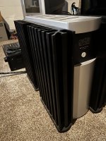
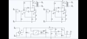
Early this year, I completed my first "from scratch" tube amplifier build. I used JE Labs 2A3 Deluxe schematic. Prior to that, I had only built kits (Audio Note Kit DAC 2.1, Bottlehead phono stage, Bottlehead Crack).
The JE Labs amp sounds great (to me!), but as I develop a deeper understanding of the ins and outs of tube amplifier circuit design, I suspect that I could do a lot better. (Those of you who hate two-stage driver circuits and/or 2A3s being driven by 6J5/6SN7, I've read plenty of your posts and am sympathetic to those views.)
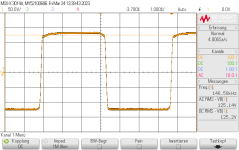
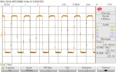
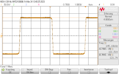
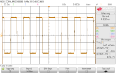
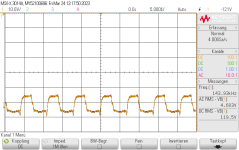
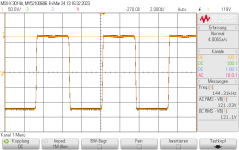
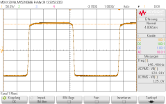
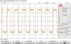
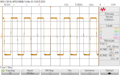
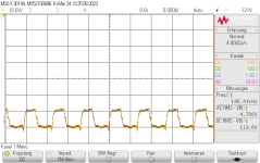
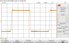
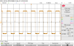
I borrowed a rudimentary oscilloscope from a friend and, during my short time with it, observed asymmetrical clipping near maximum output volume using a Type 76 tube. I'm guessing that that had to do with the 6J5 operating point but I am not sure.
Two issues that I want to explore (beyond making sure I have the fundamentals of the operating points down):
- Global negative feedback
- Lowering gain
The circuit can be found here:
JE Labs Arkiv (up to 2008): JE Labs SE300B Classic and Deluxe
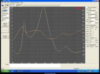
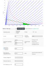
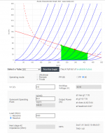
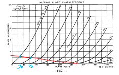
But first I want to know if I'm understanding the operating points correctly. I'm attaching a few images illustrating the following:
- Type 37 operating point (input tube)
- 6J5 operating point (driver tube)
- 2A3 operating point
I hand-drew the type 37 since
Universal loadline calculator for vacuum tubes - Vacuum Tube Amplifiers - DIY does not support the type 37.
The type 37 is biased at -2.2 V and swings between ~30V and 75V, with quiescent current @ 2.2mA.
The 6J5 is biased at ~-70V, the plate swings between 240V and 320V, and has quiescent current @ 3.18mA.
The 2A3 is biased at ~-50V, the plate swings between 270V and 420V, and has quiescent current @ 56.8mA.
I determined the quiescent current by dividing the voltage at the cathode by the cathode resistor.
The "Universal Load Line Calculator" shows that the 6J5/6SN7 operating point is pretty awful. It may actually be worse than the chart shows, since I am unclear on whether or not the "load" that I enter into the "Universal Load Line Calculator" should just be the anode resistor (22 kOhm) or the anode resistor + the cathode resistor (44 kOhm). If I use 44 kOhm, the load line is really atrocious.
6J5 Operating Point?
At this point, I'm not sure what's preventing me from changing the quiescent current of the 6J5 to ~6 from ~3 mA. On the load line calculator, that change moves the 2nd harmonic distortion from 4.39% to 1.22%. This would simply involve modifying the cathode resistor (I believe?). But if I do that, do I compromise the operating point of the 2A3? I'm not against also modifying the 2A3 operating point--I just don't know what happens with the 2A3 if I change the operating point of the 6J5.
Too much gain? Negative feedback?
As I mentioned, the amp sounds great, but I believe I have too much gain. My DAC is ~2V RMS out and the volume control on the amp doesn't need to go much higher than 10 o'clock for things to be pretty loud. I suppose that means I could implement some global negative feedback into the circuit to control that? It would be a fun exercise to implement a switch which would let me turn the feedback element on/off at will to see how it affects the sound.
Otherwise, would moving the overall operating point of the 6J5 "to the left" accomplish a reduction in gain? Or, just by virtue of the tubes used, is the amount of gain present in the circuit set in stone?
Other options?
Obviously one option to pursue is a CCS for the 6J5 and use it to establish a constant operating current of ~6 mA, which should keep it (for the most part) below max dissipation.
For those that want to suggest I scrap it and start over with a single-stage driver--eventually I would like to do that, but for now, I want to move incrementally and see how changes to the circuit affect the overall sound and performance.
Thanks for your time!
