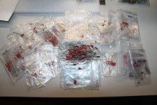
Tubelab SSE build Capacitors

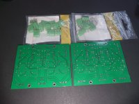
For Sale: I have some tubes and (2) Tubelab SSE PCB’s

Probably best for someone starting out and wants to roll tubes or plays guitar too.

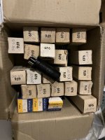
(8) Shuguang “Coke Bottle” 6L6GC tube. I used two of them in the Tubelab SSE for a couple hours. I have no way of testing them. They are all clear. One tube is different style than the rest.

(2) Matched pair of JJ 6CA7. Never used.

(2) Matched pair of JJ 6L6GC. Never used

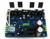
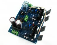
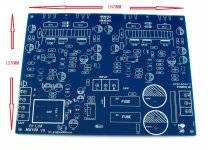
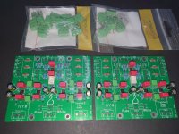
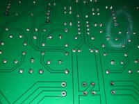
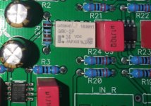
(2) Tubelabe SSE PCB’s. NOS. Never used.

The Shuquang site says the coke bottle style has been discontinued.

I would like to sell the kit as a whole. $325 shipped in USA. PayPal only. Thanks
IMG_1629.JPGIMG_1628.JPGIMG_1627.JPG

Xsim 2way crossover.

Hi, Im try to use Xsim. But not coming long. Im building a speakerbox for the beach. Two 6.5 inc woofer on each side facing to the sides, and two tweeter facing the forward ( to the listener ). Gone drive it with a 2+20W class D amp. Using Focal Polyglass 6.5 inc and Scan Speak D3804. I dont know how to get and put in the ZMA files. Can I watch at the curves without the files or are there to much information missing? The woofer and tweeter has almost same sensitive dB and Re.

Frank
IMG_7051.jpg
IMG_7049.jpg
IMG_7048(1).PNG

Cardioid whack & boom how to prevent?

Yesterday i heard several cardioid subwoofer systems for a big audience (40K). I found the bass to be cartoonish, like old batman cartoons "Whack" & "Boom" one note. If you could improve the sound quality of a cardioid subwoofer array? How would you go about it? If sound quality was number one. Closed box, bigger bandwidth, improve spacing? All physical option in the design of the line itself, without sacrificing directivity, what would be possible?

can anyone offer help understanding the flow of this circuit

Hello, good day everyone on this forum. i would like to know if there is anyone here that could explain the basic operating principles of this amplifier. 1 channel is down and ive replaced all the diodes and semiconductors but still have 69vdc on q7 transistor.......i have already removed all the mosfets from this channel and still get 69vdc at the base of q7 ? any help would be appreciated thanks Frank........the board number is 1806 ...this is a soundcraftsmen pm860

Attachments

Volunteer for testing an I.R. remote for Nakamichi 1000ZXL

Hello,

After a (too) long silence, I have finally completed my Wireless remote control for the NAKAMICHI 1000ZXL / 700ZXL: it has already been succesfully tested by two ZXL owners, but I would like another volunteer to test it, in order to be 100% sure that there is no issue !

The volunteer should be located in Europe to avoid the Customs paperwork...

The system can remote control a Nakamichi 1000ZXL via a dedicated (not a chinese generic) I.R. remote control, with the names of the buttons matching properly the names of the original wired RM-300.

An Android Smartphone application is also available to use your Smartphone instead of the I.R. Remote: it can be useful in case of something hides the infrared signals, such a TV screen for example.

The system supports ALL the original RM-300 functions, including all the RAMM functions, with the exception of the Cueing 1/6th that is not supported by the current Firmware version.

Here are a few photos:
ensemble boitier et zappette2.JPG

zapette RM-300_AVE_bordures.jpg

Please contact me if you are a volunteer to test it.

The price of the system is not yet defined, but if you are a volunteer, you will only be charged by the costs of parts (no labour, no margin, just the costs of the parts).

Thank you !

Advice needed: mono > stereo headphone amp build

I've built this headphone amp (before I knew about diyaudio): https://www.instructables.com/Make-a-Headphone-Amp/

I want to use it to amplify a mono signal into stereo headphones, so I put in a mono jack for input and ran the tip to both channels of the volume pot (the first thing in the circuit). My audio probe and plugging into a stereo audio recorder both tell me that the signal is getting to both channels in the (stereo) output jack, but through the headphones I get near silence. Any idea of what's going wrong? or suggestions for how to fix it?

UPDATE: the output signal stays the same strength even if I unplug the battery or take out the opamp. In fact, I put in a new opamp and got a loud signal through the headphones for a split second, which suggests I've done some bad wiring and blown the opamp somehow. (Any tips on why opamps blow much appreciated.)

Thanks!

From a fellow audio enthusiast

Hello Guys,

i have been reading for a while now , have not posted anything yet . So time to change that .
I have an electronics background, and looking forward to working on some valve and solid state projects .
I really appreciate the atmosphere here and a wealth of knowledge and experience that lurks within the community.
Best Regards
Mil

P.S.
much thanks to the admins for sorting out my posting issue.

Three-way or not?

Hi everyone.
I have a question about speaker ways.
The manufacturer wrote in the technical specification that the loudspeaker is three-way, however the crossover diagram shows that is not three-way.
Could someone explain this to me?

Attachments

  • A.jpg
    A.jpg
    125.4 KB · Views: 119
  • HTC crossover.jpg
    HTC crossover.jpg
    24 KB · Views: 103
  • TW MF.jpg
    TW MF.jpg
    363.2 KB · Views: 102
  • WF.jpg
    WF.jpg
    146.3 KB · Views: 92

Tweeters Scanspeak D3004/664000 beryllium illuminator x2 400e

Like new, only used for testing, i'm letting them go because i can't afford them, best tweeters i've ever had btw !

Shipping everywhere, paiement by paypal of bank transfer

Selling for 400€, price new is 1000€, still have the invoice

Attachments

  • IMG_20220627_234428.jpg
    IMG_20220627_234428.jpg
    477.1 KB · Views: 185
  • IMG_20220627_234412.jpg
    IMG_20220627_234412.jpg
    389.4 KB · Views: 186

DIY “datsV3” not working

So, I followed a guide on YouTube as to how to build a measurement cable for getting TS parameters and impedance curves from drivers similar to how the datsV3 works. It’s basically a few 3.5mm jacks, 100ohm resistor, and some alligator clips to attach to the driver. I then bought a USB sound card to plug into my laptop.

The problems arise when I try to run the calibration on the cable in REW. The open loop part works just fine. When I try doing the shorted calibration sweep though, it comes up with an error saying that the input level is too high in comparison to the reference output.

When I test continuity and resistance everywhere on the 3.5mm jacks, it all checks out. No shorts, nothing is mismatched, and nothing is “open” where it shouldn’t be. I’m wondering if the guide that I followed is simply out of date because of an update in REW(he’s obviously using an older version in the video), or if I’m missing something. I did figure out that I have to use a stereo jack instead of a mono jack for the mic because this sound card only accepts a stereo jack on the mic input. So I just soldered the two positives on the jack to the one positive wire going to it.

For Sale Twisted Pear IVY III modules (2x)

I am selling two Twisted Pear IVY III modules.
The terminal blocks are not mounted, but included. J1-J4 are not populated.
R32-R35 are only populated on one board.

The price is 50€ per piece plus shipping (from Germany).

Regards Martin

Attachments

  • Boards_1.jpg
    Boards_1.jpg
    496.2 KB · Views: 172
  • Boards_2.jpg
    Boards_2.jpg
    415 KB · Views: 180
  • Boards_3.jpg
    Boards_3.jpg
    285.6 KB · Views: 136
  • Boards_4.jpg
    Boards_4.jpg
    412.8 KB · Views: 173

PCM1794 -- simplest I/V possible needed

In the
Testing the pcm1794 thread,
https://www.diyaudio.com/community/threads/testing-the-pcm1794.221743/

smms73 described an I/V test rig comprised of:

this test was made by connecting the pin IoutL+ to a classical ampop I/V converter (opa2134) with a resistor of 50 , 100, and 150 ohms in series.

the pin IoutL- was connected to ground.
https://www.diyaudio.com/community/attachments/opamp-iv-png.306974/

What I need is fast solution to getting acceptable sound from the output of a PCM1794. Something one just plugs RCAs into and get okay sound (or at least a hint of what is possible with the PCM1794)

Will the test rig described above suffice?
Or does one need more stuff added?

Moving from Intel to Apple Silicon

I was not sure where to post this soI thought this forum would be most appropriate.
I have been writing for Dolby Atmos on a 5,1 Mac. I used open core legacy patcher to get me to Moneterey. This worked but was a bit buggy and I eventually tried Ventura as this has enhanced ATMOS support in the OS. SO when my work gave me a MacBook M1 Pro, have been doing some research because I do not wish to change my RME Raydat which is PCIe.
Also not using a laptop before in the studio brings other problems such as having to unplug all the connections all the time. We have use Sonnettech computer housings at work for years, but they also make PCIe caddy as well as some very useful docks.
My Raydat was bought in 2009 and still going strong. The ports are a bit worn out but I found out I can get new ones from RME
https://www.rme-shop.com/cgi-bin/ss001802.pl?page=search&SS=toslink&PR=-1&TB=O&ACTION=Go!
So when I make the switch she will get a fresh set of ADAT connectors.
I made a couple of video of what I found on the Sonnettech website.
Login to view embedded media And some very useful thunderbolt docks.
Login to view embedded media

BIG Leap LTD & TSL difference

Sorry of this has been discussed, searching for TSL and LTD isn't exactly concise.

I was considering making a box for the Dayton Epique E180HE
https://www.daytonaudio.com/product...-mmag-extended-range-subwoofer-4-ohm-per-coil
when I noticed over in Audioxpress that there is a huge difference in LEAP's TSL and LTD measurements of the Qts,
https://audioxpress.com/article/tes...e-subwoofer-from-the-dayton-audio-epique-line
and most people go with the LTD measurements, and the box difference is quite a lot, a 35L box compared to a 185L box (sealed, Qtc 0.5).

As I said it's hard to search the definitions of these terms, so I don't know what they mean, but I do notice that many people prefer the LTD measurements over the TSL, what are they?

811a AB2 Sanity Check

Hey everyone,
i want to build a PP DHT amp next and was thinking about using the 811a as they can work on relatively low B+ and are still affordable (at least the russian and chinese versions). I came up with the following schematic:

c62a40128a59998a074851bd5c5c09f2.png


Spice says 80W at 1.8% THD but the 811s are at running hard at that point drawing 350mA peak at the plates and 22mA peak at the grids. May have to dial it back a bit. Idle current for the 811s is set to 28mA.
For heating the 811's i'd use 2x MeanWell 3.3V supplies in series. I can connect all output tubes to the same (floating) smps when using fixed bias correct?
Now i still have a few questions..

  • Are there any obvious mistakes in my schematic?
  • Is the Hammond 1650R a suitable output transformer? I suppose it would saturate at max. output, not like i'd ever run it at full power tho.
  • Should i regulate the +/- 100V Supply for the mosfets? Don't want the supply to sag too much when the grids draw current.
  • Are the russian G811's any good? Alternative would be the Psvane ones.

Looking forward to your input!

Boombox build: General port placement, size and tuning

I've built a kit or two before but I'm planning to build my first speaker design as a boombox with two TCP115-4s and SB 26STCNs. I've built a box that is roughly 8.5l tuned to around 58 hz. In the front and middle will be a closed box for an infotainment radio and the rest of the box will be opened to both woofers. Dimensions are 46x22x17cm and space is getting tight especially when using some LiFePo4 batteries at the bottom.

First question is port location. Due to there not being so much room I'm left with having to mount a single round flared port facing one of the sides. Is there some reasons this will be a bad idea? I see many youtubers and even JBL using side mounted PRs but I don't know if the extra cost is worth it nor do I like Winsid showing I'll have a lazy slope downwards when I want this to "boom".

Second is the port width. I have the options of using 35, 42.7 an 50mm ports. Winsid shows that the 50mm first port resonance is 1017hz. I read about subwoofer port resonance but it doesn't really satisfy my situation. The crossover point will be around 2400hz if this helps. What size port is usually used for 4" speakers?

3rd is the tuning. Essentially each TCP will be getting 4.25L and winsid projects a 1.5db bump occurring around 60hz and the f3 being around the speaker's FS. From vituixCAD the FR starts rolling down around 100hz. With the woofers getting their rated power, will I run into any mechanical issues?

Any other advice would be welcomed. The wood is 15mm and there is some battens and extra bracing for the radio enclosure inside the box. This is my first iteration and I mainly want to use it to test what will work and what won't especially since some of my friends already want me to build them one already, heh. Perhaps one last outgoing question is what to do concern putting foam inside the box. In my country I can easily get 1-2cm foam for the walls and polyfil but will a more polyfil solution be better?

Attachments

  • boombbox.jpg
    boombbox.jpg
    284 KB · Views: 171

passive line array tops

A friend recommended I look at the Mackie DRM12P tops, but I haven't found much info on them. I was also looking at the Presonus CDL12P tops (which I have heard and installed in a couple churches). I'm mostly doing clubs and currently have 4 JBL SRX722 tops, which work fine, but don't have the same coverage as line array tops.

Anybody hear the Mackie stuff or have other passive line array top recommendations that won't break the bank?

F-5 Questions....

A good friend designed new power supply and amplifier PCB's for the F-5 based on the large IXYS devices. A few made comments on the F-5 when using these devices, and I was not sure what to think. I would appreciate if you all could chime in on what was said, especially those that may have used the large IXYS mosfets. His amplifier runs fine and he says sounds excellent.

One guy said...

"Beautiful boards. But those MOSFETS have CIS values in the11.5 to 14.5 region, and driven by impedances in the 470 to 680 ohm region. You will have poles at 11 khz and 20 khz This means serious risk of self oscillation at 25 khz."

"And to remedy that, one will need to limit the bandwidth of the X10 gain amplifier into 2.5 khz or less.

He is sending me a set of boards so I can build one, bu5t it would be nice before hand if what this guy says in an issue.... I am really looking foreword to this project....

Thanks in advance for commenting on this... I decided to make a seperate post so it did not get burried in the main F5 post.

Mark

Attachments

  • Pass F5.jpg
    Pass F5.jpg
    85.6 KB · Views: 695
  • Pass F52.jpg
    Pass F52.jpg
    75.5 KB · Views: 678
  • F5 3.png
    F5 3.png
    190.2 KB · Views: 677

Anyone have a Consonance/Opera M99 or M100 integrated amp, I'm starting to mod mine

I have had this amp for about 10 years and haven't done much with it other than play with different tubes. I started looking around the web for info on it and found most pictures and reviews showed it having 6L6 outputs, but the 3 different schematics I found showed EL34. The other odd thing I noticed is that 2 schematics showed it connected as a pentode, the other shows connection to "ultra-linear" taps, but all still EL34s. Mine was connected as pentode with G2 connected to B+ thru a 10K resistor and G3 tied to cathode. I pulled the output xfmr caps off and found they actually have the UL taps, so I have connected wires to them and run them down into the bottom area. while I had it apart I decided to check the transformer impedance ratio, turns out it's 4.4K P-P and the taps are 43%, pretty much standard UL configuration. So now I wonder why they would have built it like this? The other odd thing is that they indicate the bias is different for each output tube, and they use different plate resistors in the driving 6SN7, I have no idea why it's built this way?

Anyway, the amp is well built and I am going to play with it in various configurations. First, start with figuring out which tubes to use, 6L6 or EL34.

Your thoughts?

Cheers

M99.jpg
  • Like
Reactions: 6A3sUMMER

Constant directivity horn to 800Hz for a 2" compression driver.

For a personal project i want to use that exellent Faital HF201 mated initially with a 10" woofer i already have in a cabinet that is good to 800Hz (altough i may to to a 12" later) in a constant directivy horn. But it seems that those are not that common. I used that driver a few times for others already with the P Audio 2380 clone of the JBL horn and in that horn it works well, but it's not constant directivity and it's dispertion is to wide for my home use. Off course i could contact people who make custom horns for this, but that is way out of my budget. Are there ready made horns like that with a 70 to 60" horizontal dispertion that does not cost too much (under 200€ for a horn)? Crossover will be dsp anyway as the sensivity difference will be to big to do it passive.

The 18sound XR2046 is the style of horn i would like to have, but it does not load low enough for my use. Other drivers are not really the goal, i really want an own home setup with that HF201, as it's sound, even unequialised is the kind of sound i like a lot. Other Faital drivers are close and sound very good, but not close enough.

12P17L or 2P29L In Pentode As Output Tubes In Amp?

I've seen posts about the 12P17L, which is basically an indirectly heated version of the 4P1L. But they all seem to be using them in preamps wired in triode. My interest in these is, in part, because, being indirectly heated, they presumably don't have the issues with microphonics which the 4P1L has and could be heated with AC.

Anyone try them in pentode as output tubes in an amp? Yes, I know they will be less linear.

I'm considering either a breadboard experiment or maybe dropping them into a vintage console amp chassis. This is mostly out of curiosity so simple, cheap and junkbox parts are the order of the day.

I saw one post by Wavebourn in which he mentions a vintage farm radio that put out 10w using PP 12P17L. In PP, what OPT primary impedance would be best and how much drive would be needed in order to get 8-10w per channel? And what operating points?

I've also seen some discussion about the 2P29L, which is a directly heated pentode but, again, only used in triode for preamp duty. I did try the 2P29L last year when I was breadboarding preamps and it sounded very good. Part of its appeal is that, despite being directly heated, it seems to be immune from microphonics.

Anyone try them in pentode as output tubes, either SE or PP? How much power output could I expect? Again, what OPT primary would be suitable and what operating points?

  • Locked
BEWARE WITH KLYPSO or you will be scammed

BEWARE WITH KLYPSO or you will be scammed like I was with this pair of tweeters:
https://www.diyaudio.com/community/...-664000-beryllium-illuminator-x2-400e.398493/

An empty box with just papers inside. He covered himself from the paypal buyer protection sending an empty box.
Anyway, I paid him like friends and family and I have no chance to recover my money: 400€ + 9€ shipping.

Yesterday morning I received the empty box and tried to get in contact with him, but, as it could be supposed, there was no answwer.
9610.jpg


I reported this scam to local Police in Spain and would appreciate if any French user could report this to French Police as well, because I cannot.
I could give him all the necessary data.

TDA1545 / TDA1543 and Vref (pin 7)

The datasheets for both the 8-pin TDA1543 and 1545 dacs note a Vref connection to the non-inverting side of the right and left I/V op-amps. See schematic for both DACs (pg 3 or pg 4).
http://www.lampizator.eu/lampizator/LINKS AND DOWNLOADS/DATAMINING/tda 1543.pdf
http://vasiltech.narod.ru/files/TDA1545A.pdf
Pulling out my old projects, I realize that for the discrete (non-op amp) I/V stage I built, I did use the most of the datasheet schematic but did not connect Vref (pin 7) to the I/V.
I recall other DIYers at the time doing the same thing.
And sonics are very good and clean.
However, in OEM cd players that use TDA1543 (or 1545), the service manual schematics [example from hfiengine.com: hfe_philips_cd110_130_140_service_en.pdf (1543) : https://www.hifiengine.com/manual_library/marantz/cd-36.shtml (1545) ] do use the full datasheet suggestion, including "elaborate" connections to the I/V opamps..
How important is to connect Vref to the I/V (opamp or discrerte) ?

Wharfedale Diamond 9.1 - different Versions ?

This two way bookshelf loudspeaker is known for good sound and cheap at the same time.
Obviously there are not only one exist Version - go to the attachment.
I note, that one tweeter use a diffuser lens. Which of both versions is to prefer ?
Thanks for an advice.

Attachments

  • 2517611742fa85ec07b88c5277de.jpg
    2517611742fa85ec07b88c5277de.jpg
    128.6 KB · Views: 605
  • b938c6ec43e8915e634d55f95cc6.jpg
    b938c6ec43e8915e634d55f95cc6.jpg
    120.1 KB · Views: 317
  • Wharfedale-Diamond-91b.jpg
    Wharfedale-Diamond-91b.jpg
    132.7 KB · Views: 380
  • Wharfedale-Diamond-91c.jpg
    Wharfedale-Diamond-91c.jpg
    106.4 KB · Views: 595

Implementing the chassis earth/protective earth.

G'day Guys,

A question regarding implementation of the chassis earth / protective earth (whatever one wants to call it)

I have previously used the implementation from Rod Eliots Site.
earth-f3.gif


I was looking inside a PA amp recently and saw a slightly different approach of the screw going down into a tapped hole in the chassis rather than up into the chassis.
20230406_205517.jpg
This approach perhaps makes more sense because as I understand it, legally the protective earth should be unable to be unscrewed from outside of the amp. With the approach provided by Rod one could plausibly unscrew it from the outside whereas this is basically implausibly with the PA amp approach.

So now comes the question:

Could this be more optimally done using a rivet nut?
Something like this
alternate ground 1.png

The advantage I can see is that one has much more thread area with a rivet nut that with a simple tapped thread through the sheet metal of the chassis.

Is it possible that the contact area with the rivet nut to the sheet metal is less than the contact area of a tapped hole?

For the record, the sheet metal that I am currently using is 2mm electrogalv steel.

Linn's SPKR005/1 (LS150 HELIX) and SPKR012/5 (LS-150 HELIX/INDEX-II) - Replacements ?

Linn's old tweeter from first speaker series (Isobarik DMS, KAN, SARA and even NEXUS) are based on the 50 years old Scan-Speak D2008 and replacement is still available (produced from Hiquphon model OW-1 - even Scan Speaks D2008 is still available) - go to the images 1-3 and
https://www.scan-speak.dk/product-families/classic/

But what about the tweeters for the HELIX (first series) - go to image from No 4 and HELIX/INDEX-II (images post #2) ?

Attachments

  • Linn D20-LP-1-front.jpg
    Linn D20-LP-1-front.jpg
    67.1 KB · Views: 151
  • Linn D20-LP-1.jpg
    Linn D20-LP-1.jpg
    45.1 KB · Views: 136
  • Hiq_OW1_Linn_Kit_edited-2_2048x.jpg
    Hiq_OW1_Linn_Kit_edited-2_2048x.jpg
    421.1 KB · Views: 121
  • SPKR005-1 front.jpg
    SPKR005-1 front.jpg
    135.5 KB · Views: 121
  • SPKR005-1.jpg
    SPKR005-1.jpg
    146.7 KB · Views: 125
  • SPKR005-1-V.jpg
    SPKR005-1-V.jpg
    149.3 KB · Views: 135
  • SPKR005-1-IV.jpg
    SPKR005-1-IV.jpg
    150 KB · Views: 120
  • SPKR005-1-III.jpg
    SPKR005-1-III.jpg
    169 KB · Views: 143
  • SPKR005-1-II.jpg
    SPKR005-1-II.jpg
    205.8 KB · Views: 123
  • SPKR005-1+BM.jpg
    SPKR005-1+BM.jpg
    167.3 KB · Views: 151
  • HELIX-SPKR005-1-front.jpg
    HELIX-SPKR005-1-front.jpg
    28.2 KB · Views: 126
  • Helix-SPKR005-1 rear.jpg
    Helix-SPKR005-1 rear.jpg
    233.2 KB · Views: 133

Mouser Restricting Sales to Some Hobbyists

Mouser has started restricting sales of some items to some hobbyists, with Mouser having arbitrarily decided that the affected hobbyists are actually 'Specialty Distributors' reselling certain items. This can occur despite no reselling or distributor activities having ever taken place.

Some commentary out on the internet:
https://rb.gy/t5eq2
https://rb.gy/neb1i

Just a heads up in case it happens to you.

Sony DVD lasers: KHM-310BAA, KHM-270AAA, KHM-240AA: how do we clean them?

Sony DVD lasers: KHM-310BAA, KHM-270AAA, KHM-240AAA: how do we clean them?

I recently obtained a Sony DVP-NS775V DVD/CD/SACD player for $15 USD.

My interest in vintage Sony DVD players (such as DVP-NS775V) focuses on models which play the SACD format. Among them are DVP-NS500V, DVP-NS755V, DVP-NS775V, DVP-NS975V, & DVP-NS90V. The superb DVP-NS999ES is also among these models. But it’s nearly impossible to obtain a DVP-NS999ES for $15. In contrast these other SACD-compatible models can often be purchased for <$25 USD.

But this DVP-NS775V had a problem: Every interior surface was coated with a thick film of very fine white powdery dust. It looked and smelled like the residue from sanding & finishing drywall (gypsum board, plaster). This DVD player was clean on the outside, probably because someone had thoroughly wiped it down externally.

Unfortunately this white powdery dust thoroughly coated the laser lens. This disabled the machine. Discs would spin at various speeds for 1-2 minutes followed by a “cannot play” error message.

With isopropyl alcohol & a fine-haired brush I succeeded at cleaning the lens. This permitted the machine to play standard CD discs.

But plenty of this white dust was also present inside the optical pickup. Using considerably more alcohol and compressed air I removed most of the dust from inside the laser pickup. But not all of it. At this point the machine would play both CD & DVD, but still refused to play “hybrid” SACD/CD discs. There was still too much dust inside the optical pickup.

So I began disassembling the optical pickup. The thin metal cover underneath snapped off easily. This exposed the internal glass mirrors which direct & split the laser beam. The plastic cover on top of the pickup was also easy to remove. This exposed the focus/tracking mechanism which positions the upper lens.

However there is another lens directly underneath the focus/tracking mechanism. This lower lens could not be cleaned except by temporarily removing the focus/tracking mechanism. This is where I got into trouble I think. It was easy enough to remove the focus/tracking mechanism, just 2 tiny machine screws. This allowed me to clean the lower lens, which was also heavily coated with the white dusty powder.

After cleaning the lower lens & reassembling however, my progress backtracked to where the machine would barely play a standard CD. I suspect I misaligned the optics by all of my disassembly/reassembly.

So, my question is this: Have any diyAudio members successfully disassembled/reassembled a Sony optical pickup?

-EB

DIY small monitor

Hello everyone,

I'm looking for DIY monitor to complement my Harbeth p3esr, it cannot be much bigger than the harbeth since I have them at a desk, and it's for nerfield listening. I found the Seas Curv and the Eekels mini both from toels, but cannot find any sound description on them. Oh and it should be comparable in quality with the harbeth otherwise I wont use them.

The DREAM Project

A 20 year-old fantasy, finally "a dream within a dream" ...

Bottom line:
Plug-n-chug myriad diy digital devices into a common battery-powered headphone-amp/IEM combo, with swap time < 1min. Take notes. Compare/contrast. Report as necessary. This thread as main reference.

Other DREAM features:

COMMON: Input (line) device -- such as a well-functioning, up-to-spec CD player (shown); and output stage (as shown: Rudolf Broertjes’ SS I/V Gain Stage, much-modded ).
In-BETWEEN: "Plug-n-chug myriad diy digital devices"

Other goals :

Plug-n-play (but not hot swap, to protect electronics!)
Occams' Razor
All-things/else-held equal
ABX and objectivitist-freindly
Use of test equip. and software for metrics and data acq.: FLIR, DSO, SA, Cosmos ADC.
"Bottom line" is a combo of tools, techniques, developed over time, and its evolution.
Update this thread as necessary.
Vocabulary and grammar: Noun, verb, adjective, adverb, preposition, metaphor, etc.

More coming soon ...

=======Some photos below have been prev. posted in other recent threads or posts ======


Line-up (Overview) of Vintage Receiver Models with AC Speaker Output (not DC) wanted

I am looking for an URL, where are listed all vintage stereo AM/FM receiver so as vintage integrated amps/power amps, which have no DC coupled (resp. no direct coupled) loudspeaker outputs (i. e. a serial capacitor between output and speaker terminal).
Serial capacitors are in use more like in older models, the newer ones have often been changed to symmetrical voltage suooly and direct coupled speaker output. An example is the Marantz 2230 (AC coupled output) and its successor 2230B with DC output (see attachment)
Pioneer, Kenwood, Sansui and much others really should also have such devices built. The SX300 is an additional example - have a look to the pics from
http://www.hifi-forum.de/viewthread-84-11738.html
The great advantage is the possibility, to replace the caps in series to the speakers against precisely tailored values for getting best sonic results in the lower frequency aera (also in order to the corresponding loudspeaker allocation - e. g. sometimes near by the wall and sometimes not) and the absence of serial contacts from relays for DC protect. This is not easy to reach with DC speaker outputs.

Who can send me an advice for such URLs??
in the attachment you will find another example from the Marantz 1060
Thank you for your advices.

Attachments

  • Marantz 2220.jpg
    Marantz 2220.jpg
    121.4 KB · Views: 521
  • marantz-2220B - direct coulped (DC) output.jpg
    marantz-2220B - direct coulped (DC) output.jpg
    23.6 KB · Views: 530
  • Marantz 1060.jpg
    Marantz 1060.jpg
    103.3 KB · Views: 481
  • marantz 1060_2nd_ 006.jpg
    marantz 1060_2nd_ 006.jpg
    204 KB · Views: 508
  • Pioneer SX300.jpg
    Pioneer SX300.jpg
    351.3 KB · Views: 484
  • Pioneer SX300T.jpg
    Pioneer SX300T.jpg
    133 KB · Views: 274

The SAA7220/TDA1387 project

When the '87 remaster of Tales of Mystery and Imagination came out, I immediately preferred it to the orig' 76 in almost all aspects. The MOFi LP and Gold CD improved the '76, but the 2007 remaster (both versions), loudness compressed things horribly! The '87 digital remaster, ironically, sounds best on LP. More recent remasters, including 4oth anniv have bonus material. Almost 300 versions released:
https://www.discogs.com/master/4322...ion-Edgar-Allan-Poe?sort=year&sort_order=desc

Which brings us to another '87 ... the tda1387. Remarkably, no one -- ttbomk -- has preceded it with the classic SAA7220. Still testing it out in the same rig as the TDA1545/DF1704 experiment.
Results promising. Stay tuned ...


USB XMOS + SHARC DSP + ES9016 DAC ... I2S question

Trying to figure out how connection of xmos, dsp and dac should look like.
DAC
https://www.diyinhk.com/shop/audio-...84khz-32bit-es9016-pcm-dxd-dsd-audio-dac.html
DSP
https://www.aliexpress.com/item/32978121788.html
i took only small board with DSP + USBi interface
XMOS
CM6632A based, there is software available for both Master and Slave mode I2s

What worries me is that on DSP side i only have single pins for clocks for both input and output.
Pinout i got in description from aliexpress seller:

  • FS(96KHz) A11
  • CLK(6.144MHz) A8
  • Master CLK(24.576MHz) A14
  • IN A/B A9
  • IN C/D A5
  • OUT1/2 A6
  • OUT3/4 A10
  • OUT5/6 A20
  • OUT7/8 A15
So how to connect all this? Can I just 'split' clocks from dsp and connect to both in and out on dac and xmos??
If needed i can post all the pinout and schematics i gathered.

Attachments

  • i2s.jpg
    i2s.jpg
    113.8 KB · Views: 234

Design Question

I've had this board laying around for a few years and decided to build a schematic for it. I've two questions about this thing???
1. Why would the designer use a TIP42c and a D880 for the drivers? Why not a TIP42c and its compliment, TIP41c? Or D880 and B834?
2. Is there a design name for this type of araingment, LTP. VAS, driver stage... I notice there is no bias adjustment and would not even know where to integrate one.
Any advice is welcome. I have not powered it up yet...
Scott

Attachments

  • c5200_a1943.jpg
    c5200_a1943.jpg
    165.1 KB · Views: 202
  • IMG_0749.jpg
    IMG_0749.jpg
    807 KB · Views: 186

SEAS 8EN/G-EXM

Hello I am selling these Custom Seas Excel C18EN/G-EXM drivers.

These has been mounted in a pair of Ex Machina monitors and have been replaced by their MKII drivers. These are very rare and not available for purchase anywhere and are only made for Ex Machina.

25mm/1” GrapheneQ™ tweeter, coaxial alignment with midrange.
176mm/7”” Textreme™ carbon-fiber midrange, underhung surround, FEA optimized geometry for tweeter waveguide.

Price: 1.600 € for the pair.

Attachments

  • IMG_2187.jpeg
    IMG_2187.jpeg
    366.5 KB · Views: 114
  • IMG_2188.jpeg
    IMG_2188.jpeg
    416.8 KB · Views: 120

Kicad how to do a relay or other component in parts

I'm learning how to use Kicad and have a jpg schematic for a relay attenuator where, for clarity, relays have been split into three sections, solenoid, switch1, switch2. Neat I thought. But how do I do something like this in Kicad?

destructed relay.jpg


A link to a site or tutorial would do. In part at least the problem I've had is knowing what terms to search for to find the information I want. I understand I could create the symbols myself, but don't know how I'd link them together so that for the pcb I'd have a single footprint. Or even if that's the right approach.

OP AMP circuit mods?

I have this 4-channel "Color Organ" in a previously finished project.
And it performs nicely to animate the colored lamps to the music.
Yellow=trumpets - Red=vocals - Green= lower vocals - Blue=bass notes.

However, one thing bugs me....
The lowest frequency just isn't low enough for my tastes.
The "Bass" section of the IC activates higher than I'd prefer, and I'm in a bit of confusion on making it activate at a lower frequency.
As shown, it's around 300Hz.
I have tried 0.1uf caps in place of the 0.47uf, but the lamp doesn't even activate at all. ( actually jumped the .047's with another .047)
I want it to center around 80 to 150Hz.
Anybody here have any positive (not guesses) ideas on how to mod the existing circuit (caps, resistors)?

This is the circuit.
ORGAN PARTIAL.jpg

Polk 10A monitors

I just bought a pair of Polk 10A monitors from goodwill for $120. Cabinets and grills are undamaged but pretty dirty. The surrounds are complete and supple and they have the Peerless tweeters. They have fuse holders but no fuses. I jumper'd the fuses to test them because goodwill allows for returns if stuff doesn't work. I tested them with my garage receiver (25W Yamaha Natural Sound) and they sound pretty good. I am not going to play them again until I get the fuses. Does anyone know what value and type of fuse these should have? I've had no luck finding a detailed schematic.

PS Audio M500 power supply schematic?

Does anyone have a schematic for the PS Audio M500 power supply that came with the 5.5 Preamp?

I have a 4.6 preamp which still works well, but the power transformer in the separate power supply is buzzing. I have sourced a new torroidal 28v-0-28v transformer, and built a nice replacement power supply. The optional PS Audio M500 power supply apparently contained a few additional components: 2 1uF caps, a small rectifier, a bleed resistor, etc
I am looking for a schematic to follow to add those parts. Thanks.

Solder or plugs

Hey all just wondering what the pros and cons are of soldering vs spade plugs for attaching the speaker and connection plates within a speaker enclosure.

This will be for my passive DIY Subs, so no crossovers or amp units, just connecting the two drivers to the back of terminal plate.

Soldering the entire lot could be a PITA and require extra cable.

Will spades offer sufficient contact area?

Maybe solder the connector plates and plug the speakers? or just plug it all?

FS - Temaad 10.5'' Uni-pivot with magnesium arm wand

Hi for sale my 10.5'', reason for selling, going to 12''.
Arm has had light use & Eff Mass is 20 grams. This arm cab be used with standard alignment but really shines when used with Under - Hang.
Comes with Arm Base adaptor that allow arm to be fitted to virtually any T/T
Price $380 plus postage from $25. PayPal accepted

Cheers

Attachments

  • DSC05297.JPG
    DSC05297.JPG
    498.5 KB · Views: 169
  • DSC05298.JPG
    DSC05298.JPG
    284.5 KB · Views: 159

10uf Film Stealth Caps. Audio Research

I bought these from this thread:

https://www.diyaudio.com/community/...ealth-caps-audio-research-custom-made.380821/

I am selling six of them as I have too much stuff and too big of a project list... The price is $20 a piece which is what I paid plus shipping. I have various PCBs as extras ordered from JLCPCB of which I can sprinkle a few useful treats into each package 😉
A lot of Pass designs use 10uf values. I have used these caps in a BA-3 for instance. The Korg B1 Nutube, the B1 etc have 10uf caps in their circuits as well.
Projects by fanatics, for fanatics
Get answers and advice for everyone wanting to learn the art of audio.
Join the Community
507,685
Members
7,884,223
Messages

Filter

Forum Statistics

Threads
406,035
Messages
7,884,223
Members
507,685
Latest member
EvenLouder