You are using an out of date browser. It may not display this or other websites correctly.
You should upgrade or use an alternative browser.
You should upgrade or use an alternative browser.
Filters
Show only:
Rpi HAT => 8 x differential analog outputs – How interesting? Competition? Difficulties?
- By JMF11
- Digital Line Level
- 26 Replies
Kii Three, D&D 8c, Neumann Monitors, Genelec…. And many others rely on digital / DSP / Class D amplifiers, one per driver => I works great. Many don't have anymore Analog sources and use only digitized music. Streamers replace turntables…
Rpi packs some much for Audio applications is a cheap small package. It has great audio features. CamillaDSP is powerful and flexible. Many cheap and great Class D differential analog input amplifiers are available around (TPA3251, TPA3255, Merus MA).
I may have missed something, but the weak link here is how to gap the multiple audio channels in the Rpi to the amplifiers. RME / Okto DAC8 / Motu4 / Focusrite do the job, but are expensive. My first answer has been the digital In / Integrated DSP NeatAmp based on the TAS3251. It works and drive beautifully my LX-Mini. Can we do more modular / versatile / cheap?
Proposal would be a HAT for Single Board Computer that would implement Linux alsa => TDM (multi-channel I2S) => DAC with 8 x differential analog outputs. Linux would be the player, the DSP, possibly the USB interface (USB gadget) or AES67 (if exists on Linux). The HAT would be seen as a 8 channels sound card. Class D amps inputs would be connected to the HAT to implement up to 8 channels. Having differential analog interface, users would have freedom to choose their module.
Rpi / HAT / amplifiers all in the same box. Or balanced XLR - 1/4" TRS to the amplifiers.
8 channels DAC with TDM inputs from ESS, AKM, TI are in the 5-30€ range. Needs good power supplies, clock, buffers, maybe a small uC.
OK, bad luck, the Rpi does not supports TDM (yet). But some alternatives do, run equivalent Linux, support CamillaDSP and MPD… Good enough? The HAT would be along the Rpi GPIO header compatible to ease interfacing with other SBCs that would have similar pinout. And maybe one day a Rpi will do TDM…
Performance target would be DAC datasheet performance, using datasheet implementation (ex not select the 90€ DAC, but select a good one that squeeze most of the performance in the 5-30€ range).
What would be your feedback on the use case? Is it something that we need? In which type of projets would it be usefull?
What would make it not so sexy? What are the alternatives it would be in competition with?
What are the expected difficulties:
I don’t have the skill in all needed areas. Would some willing to contribute?
Feedback welcomed!
Candidate DACs:
Best regards,
JMF
Rpi packs some much for Audio applications is a cheap small package. It has great audio features. CamillaDSP is powerful and flexible. Many cheap and great Class D differential analog input amplifiers are available around (TPA3251, TPA3255, Merus MA).
I may have missed something, but the weak link here is how to gap the multiple audio channels in the Rpi to the amplifiers. RME / Okto DAC8 / Motu4 / Focusrite do the job, but are expensive. My first answer has been the digital In / Integrated DSP NeatAmp based on the TAS3251. It works and drive beautifully my LX-Mini. Can we do more modular / versatile / cheap?
Proposal would be a HAT for Single Board Computer that would implement Linux alsa => TDM (multi-channel I2S) => DAC with 8 x differential analog outputs. Linux would be the player, the DSP, possibly the USB interface (USB gadget) or AES67 (if exists on Linux). The HAT would be seen as a 8 channels sound card. Class D amps inputs would be connected to the HAT to implement up to 8 channels. Having differential analog interface, users would have freedom to choose their module.
Rpi / HAT / amplifiers all in the same box. Or balanced XLR - 1/4" TRS to the amplifiers.
8 channels DAC with TDM inputs from ESS, AKM, TI are in the 5-30€ range. Needs good power supplies, clock, buffers, maybe a small uC.
OK, bad luck, the Rpi does not supports TDM (yet). But some alternatives do, run equivalent Linux, support CamillaDSP and MPD… Good enough? The HAT would be along the Rpi GPIO header compatible to ease interfacing with other SBCs that would have similar pinout. And maybe one day a Rpi will do TDM…
Performance target would be DAC datasheet performance, using datasheet implementation (ex not select the 90€ DAC, but select a good one that squeeze most of the performance in the 5-30€ range).
What would be your feedback on the use case? Is it something that we need? In which type of projets would it be usefull?
What would make it not so sexy? What are the alternatives it would be in competition with?
What are the expected difficulties:
- linux side?
- hardware side?
- others?
I don’t have the skill in all needed areas. Would some willing to contribute?
Feedback welcomed!
Candidate DACs:
- AK4458,
- ES9027PRO,
- PCM1690,
Best regards,
JMF
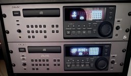
Sony CDP-D500
- By monitormax
- Digital Source
- 6 Replies
Any suggestions as to where to start modding my CDP-D500? I’ve got 2 one sounds like the soundstage is less open and sort of missing something. Less 3d I’d say . I was thinking of switching out some caps to see if that would help . Both run the 1702 chips . Not sure if changing those out would help . I do like the sound of the other CDP-D500 I have so I’m thinking might be bad caps or resistor somewhere in the other one . Any suggestions on where to start ?? Not sure what brand of caps or which ones I should replace as I’m new to this but have some experience building guitar pedals so I can solder 😎 . Any help greatly appreciated thanks
Attachments
The Grace Design M900 USB DAC/Pre/HPA is a real bargain! ($660).
- Digital Line Level
- 21 Replies
I have reviewed the Grace Design m900 for Positive Feedback Online.
- The m900 is built around AKM's latest-generation 4490 chipset, which features 32-bit processing, and supports sample rates up to 384kHz PCM or 256X DSD. The m900's four selectable digital-reconstruction filter settings are very rare at this price point, the options being, sharp or slow roll-off, and linear or minimum phase.
- In order to minimize jitter, the m900's USB interface operates in asynchronous mode, allowing the m900 to be the master clock. In addition to USB, the m900 has S/PDIF coaxial and Toslink optical digital inputs.
- The m900 can operate from USB power from the host device, or from an external power supply (provided). The High-Power supply is especially helpful when listening to difficult-to-drive headphones.
- Made in the USA, with a transferable 5-year warranty.
In my experience, for $660, you can't beat it with a stick.
BTW, the photo is from a German review. I liked the photo very much; but it is not in my review, for the usual reasons.
ciao,
john
Marantz CD67SE enlightenment appreciated
- By melmoth
- Digital Source
- 46 Replies
Hello, to all the community !
having a bit more time those days, I'm putting back on the table a project from the past....
I had, some times ago, the opportunity to buy a broken cd67se (burnt RCA connector, no display) and wanted to try to fix it (I'm not an electronic expert but hey .. let's try to learn something ; )
After some straightforward investigations, and a replaced RCA connector, I've changed two 7805 (Q811 Q871) with LM340T5. At that moment the display decided to switch on... great !
I've decided then to test rail tension and noticed and issue with the 55V one, as well as the output from 79M18 (Q851). After some diode testing, the zener D852 was dead; a replacement put all 79M18 back in business.
Currently, the player still does not work, the motor does not spin on CD insertion and the tray is very slow to open. All tensions of QF01 being ok, I strongly suspect the 55V rail being the issue (it's currently at 5v exactly what the LM340T5 is supposed to output, so I'm not fully sure of how to gain 55V from 5V ... negative feedback ? )
Investigating now around chips, I've noticed that output tension from TDA7073A Q108 is off (one being 1V the other 4V), of course none of the 7073 are properly powered with 55v, but could I have a ground sink on this TDA explaining that I'm not at 55V ?
I've also checked C155 which seem to be 47µF as well as R125 and 126 that are not 1K but only 800 ohms (I don't think it could explain the tension drop... )
From there, well I think my next step will be to desolder the 'faulty' 7073 to swap it with a presumably working one unless some charitable soul from the forum have some enlightenment or experience to share on this CD player 🙂
Thanks in advance !
A power supply for a Genesis car audio amp for home use?
- By Alex P79
- Power Supplies
- 4 Replies
Hi
Apologies if this has been asked before but can anyone recommend a neat and ‘safe’ power supply to convert 240v (UK) AC to high current 12v DC?
I have a nice Genesis Four Channel class A/B amplifier that is currently unused but, with its active crossovers, I think it could be great for driving the bass sections in my OB project.
Gordon Taylor (the amp‘s designer) has recommend a 12v/30 amp supply from Mean Well to me. I’m sure it will do the job but I’m concerned about the open nature of the connections at the front (Young children). Of course, one option would be to build a case for it but before I go down that road, does anyone know of any power supplies that would do the same job but are rather less utilitarian looking and that don’t need to be placed in a case?
I was wondering about a radio or bench power supply but would they work?
If I did go with the Mean Well I could use an amplifier chassis kit that could look nice and I would run the wires to the back panel from the mean well and then use connectors to the Genesis amp.
If anyone has any experience of connecting high current 12volt amps to home AC it would be great to hear what you think.
Regards
Alex.
Banner popping up in middle of thread
- By wirewiggler
- Forum Problems & Feedback
- 1 Replies
I get it the advertising helps pay the bills but this new action of the banner popping up in the middle of the thread is quite irritating it make the page jump up and down before settling.
Bill
Bill

First Watt Amplifier Chassis Question
Hi DIYers,
I am planing to build a First Watt amplifier, thinking of the F4 with Nelson's gain stage front end.
I picked up a junk Forte Model 6 to part out and use for the chassis, power supply and heat sinks. The heat sinks are 7" high and 8" wide. Will these accomodate most of the output boards for the kits on DIY? (I see no dimensions) Also, I have a problem, I fixed the Model 6. The thing is mint, and only had fatigued bad 8A rail fuses. I could sell the existing amplifier boards to recoup costs as the IGBT devices are valuable. Should I keep this amplifier ASIS or use it for my DIY chassis???
What Say You?
Gary
Attachments
AR3 clone rebuild
I have a set of what is best described as AR3 clones. I got them in 1998 from my father as a birthday present, so I suppose that makes them "precious" to me. They were sort of a kit, in that I soldered and installed all the individual drivers and crossovers, etc.
Anyhoo- 20 plus years later everything has failed and I would like to rebuild them.
I tried, before I knew anything about AR3s, they sounded like garbage, then I learned a bit about acoustic suspension, etc.
The drivers need to be completely / very well sealed, right?
Is there anything needed inside the cab, like wool or foam?
Repair Voice Coil lead?
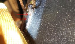
Built a system about 20 years ago using ScanSpeak 18W/8545 woofers. When I went down to listen to music this morning I found that one of the woofers had died. I pulled it out and discovered that one of the voice coil leads running up the side of the cone had broken. I probed around a bit with an xacto knife, hoping to uncover the broken area and maybe solder them back together, but sadly the leads are aluminum and very brittle. See attached picture - red arrows point to the two ends that need to be connected (might be hard to see). I don't see this as repairable since they are aluminum, so I think it is the end of the road for this woofer, but thought I'd see if anyone has a bright idea. Madisound sells a replacement so I'll probably go that route.
Attachments
Any Focal experts out here? Aria 936 tweeters
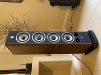
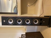
Hello, I just did a 12hr round trip drive yesterday and bought these Aria 936. I had no reason not to believe the guy when he said they sounded great, but unfortunately I just now hooked them up and both tweeters are gone. He is working with me to find out what can be done and offered to fix them. He purchased them in July 2015.
Anyone know how to get to the tweeters? Do the rings around the woofer drivers pry out to get to the screws then access it that way? I’ll be using plastic tools to pry anything on these if that is what is needed. These are 10 out 10 cosmetically.
Thanks in advance
Anyone know how to get to the tweeters? Do the rings around the woofer drivers pry out to get to the screws then access it that way? I’ll be using plastic tools to pry anything on these if that is what is needed. These are 10 out 10 cosmetically.
Thanks in advance
Attachments
Box of loudspeaker drivers for very cheap
Clearing some space for more important projects, I will have the following for sale;
2* small mdf bookshelfs. Need finishing. Vifa midwoofer and seas horn loaded tweeter. One box has drivers glued in the other has drivers non fitted and is not 'cut' to the same shape. Both cabinets rough aesthetically but suitable for playing with or re working. Vifa midwoofers have plastic frames which are damage around mounting points hence glued in. One tweeter has a permanent dent in the dome.
2* mission 8" drivers from mission 763 speakers. Foam removed, remnants of silicone sealant/glue on cone where previous owner tried to fix surrounds. Cheap chinese surrounds included if you want to learn to repair. Untested due to no surrounds.
Morel mdt 39 tweeter, tested fine.
Morel 8"woofer, something like a MW266 not sure.
2*vifa BC25SC15-04 brand new.Z
Possibly some other bits I've forgotten about.
Hope this can go to someone who will enjoy playing with them.
Looking for £50inc for the above inc. uk postage.
Can include the following for aditional ££
B&W mid drivers from xt4 - £40/pair
Yellow kevlar. Outstanding mids that can be mid woofers for low level applications in 2 way (optimised for a 3 way but free res is about 80Hz as I remember, large x-max but linear is probably just a few mm) nit one of the bullet cones was pushed in by child hands and pulled back out by gentle vacuum, it has signs of previous damage.
B&W bass drivers from XT4 - £80/4 off
1 doesn't match as it was purchased new and part of a later batch. B&W assure me it's the same specs. All look a bit tatty - please ask for pictures.
Tweeters from mission 763 (measure well and ideal for the above XT4 units, the B&W tweeter was shockingly bad) £20/pair
Less cheap:
Morel mdm55 pair £135
Scan speak 21W/8555-01 £200/pair
Hitachi HMA-9500 Schematic?
- By thermionic
- Solid State
- 14 Replies
Hi,
Ironically, the schematic for the rare-as-hen's-teeth HMA-9500 MK2 is easily found on many sites, but I can't seem to find a full schematic for the commonly-found HMA-9500 MK1 anywhere... Does anyone have a copy here?
I suspect it is based on the 2nd diagram in the Hitachi Lateral MOSFET apps data (1st diagram is the HMA-7500 / Maplin amp, with BJT-based VAS - 2nd is a FET-orientated design), but in an ideal world I'd have a schematic to check.
TIA.
NB - looking at photos, the MK2 has a few components that the MK1 lacks, so I am not sure that interpreting a MK2 schematic will be entirely advisable.
Tape Mechanism Project
- By Dibya
- Analogue Source
- 7 Replies
This is not going to be "Dragon" killer , this will be decent Sankyo 2 Head Equivalent
with enhancement of modern age like CNCed Capstan for lower Wow & Flutter.
Keeping Design Simple like Tanashin but for superior Performance.
[Having Best of Tanashin and Sankyo]
Modular: Same Base can be tweaked for Both Single/Dual Capstan & 2/3Head with Different Headblock.
I finding someone who have expertise in Mechanism/Mechanical Engineering/Mechatronics,
I can handle electronics /Microprocessor side of project , but i have zero idea in
mechanical side of it.
It will be open hardware platform, anyone can get the Mecha and build their own deck like you can go
and grab any generic OPAMP or Turntable Cartridge make your own turntable. Grab the mecha and make your own Tapedeck.
Except Capstan and Heads [Heads are made by different company] , everything will be opensource, so that their sufficient supply of parts.
Imagine a Vinyl revival without decent current production Turntable , it is not possible, More than new Tape , Cassette Revival needs new Mechanism.
Their Never going to be new Type IV tape , at max we might get decent Type II in Future, thus moving to 3.75IPS speed with 50us Time Constant will allow to have
at-least 63dbA of SNR , thats far better than most Vinyl Cartridge. Their time will come when their will scarcity of parts for Vintage Decks.
Terms of Collaboration:
Please Join me if you are interested,
Otherwise if we keep using our Vintage Deck for Casual playback , we might not have any heads left for them,
These Units are over 30yrs old atleast , can go as old as 50yrs.
Please join me if you are interested in this project.
with enhancement of modern age like CNCed Capstan for lower Wow & Flutter.
Keeping Design Simple like Tanashin but for superior Performance.
[Having Best of Tanashin and Sankyo]
Modular: Same Base can be tweaked for Both Single/Dual Capstan & 2/3Head with Different Headblock.
- Heavy CNCed Single/Dual Capstan with Optical Feedback [PLL Error Correction of Speed].
- 2/3 Head Platform.
- 1 Motor for Driving Reel [Current production Mitsumi motor can be used]
- 1 Capstan Motor [Prototype will use Pacific Stereo Motor for now]
- Good Quality Sendust/Hardened Permalloy Head [Current Production: personally talking with Maker]
- Solenoid Driven Head Block
- Full Logic Control
- Support:4.8Cm/s & 9.52Cm/s Speed
- Asymmetrical Dual Capstan
I finding someone who have expertise in Mechanism/Mechanical Engineering/Mechatronics,
I can handle electronics /Microprocessor side of project , but i have zero idea in
mechanical side of it.
It will be open hardware platform, anyone can get the Mecha and build their own deck like you can go
and grab any generic OPAMP or Turntable Cartridge make your own turntable. Grab the mecha and make your own Tapedeck.
Except Capstan and Heads [Heads are made by different company] , everything will be opensource, so that their sufficient supply of parts.
Imagine a Vinyl revival without decent current production Turntable , it is not possible, More than new Tape , Cassette Revival needs new Mechanism.
Their Never going to be new Type IV tape , at max we might get decent Type II in Future, thus moving to 3.75IPS speed with 50us Time Constant will allow to have
at-least 63dbA of SNR , thats far better than most Vinyl Cartridge. Their time will come when their will scarcity of parts for Vintage Decks.
Terms of Collaboration:
- Co owning of IP of the mechanism.
- Royalty per unit manufactured if ever.
Please Join me if you are interested,
Otherwise if we keep using our Vintage Deck for Casual playback , we might not have any heads left for them,
These Units are over 30yrs old atleast , can go as old as 50yrs.
Please join me if you are interested in this project.
Floor standing AudioFlix - 2 way SB Acoustics
I've just started my new speaker project, a 2 way floor standing using SB Acoustics drivers:
WF: SB17MFC35-8
TW: SB26STC-C000-4
Crossover point: 1700Hz
Box: 30 Liters
Tuning: 40Hz
Veneer: Oak
I'll post measurements down the road!


WF: SB17MFC35-8
TW: SB26STC-C000-4
Crossover point: 1700Hz
Box: 30 Liters
Tuning: 40Hz
Veneer: Oak
I'll post measurements down the road!
Building Mark Levinson 38 preamp chassis from scratch
- By Peter Daniel
- Solid State
- 277 Replies
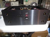
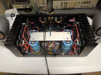
This thread is dedicated mostly to all brave people who decided to buy ML38 boards with a hope that some day they will turn it into a working preamp.
Well, for me such day finally came and here's my working version of that preamp.
Well, for me such day finally came and here's my working version of that preamp.
Attachments

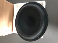
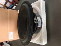
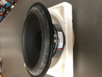
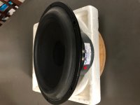
FS: Scanspeak 21W/8555-01 Classic 8" woofer
I'm selling 2 pairs (4x) of Scanspeak 21W/8555-01 8" woofers. They are new and have never been mounted or used. As they can be seen from the picture, 2 of them have the original boxes, and 2 of them don't.
21W/8555-01 has the more expensive magnesium frame, unlike the newer models (21W/8555-10) which has aluminum frame. Features are hard coated paper cone, low loss rubber surround and SD-1 motor.
I'm asking $250 shipped in CONUS for each pair.
21W/8555-01 has the more expensive magnesium frame, unlike the newer models (21W/8555-10) which has aluminum frame. Features are hard coated paper cone, low loss rubber surround and SD-1 motor.
I'm asking $250 shipped in CONUS for each pair.
Attachments
Maya 3 Aspen amp
- By Tubelove63
- AKSA
- 7 Replies
As from today I'm listening to my new amp! Just one thing notering me: there's an audible buzz, groundloop maybe? Asics from that, it sounds very promising!
Marantz CD63 (CDM-12): disc not spinning
- By darrell-k
- Digital Source
- 9 Replies
Hi,
I have a problem with a Marantz CD67. Initial symptom is that after loading a CD, "dISC" flashes a couple of times then remains on display - CD is not read.
Investigations:
Service Mode:
Mode 0 - cue/review keys both move the sled towards the outside of the disk while held down. releasing the keys sends the sled back to the centre of the disk.
Mode 1 - focus servo is operational.
Mode 2 - spindle does not rotate. (though 4.77 volts is applied to the spindle motor (measured at the circuit board connector - yellow/green wires, pins 3 & 4).
Mode 3 - sled moves towards the outside of the disc. Can be reversed with the cue/review keys. At either end of its travel, it keeps pushing at the end stops causing mechanical clicking, sounds like the screw drive pin ratcheting against the cog which cannot rotate any further.
Pressing play activates the focus servo. Without a disk loaded, "err 2" - FOCUS error - is shown (to be expected, I presume). With a disc loaded, I get "err 10" - RADIAL error. (Why not spindle error?)
I also confirmed that the spindle voltage is applied in normal operation, when loading a disk - it rises quickly but gives up after a second or two, falling back to zero. A mobile phone video shows the laser is working.
After disassembly, I applied 3 volts across the motor terminals from a couple of AAA cells. The sled and draw motors turn, the spindle motor doesn't. Turning by hand, it seems stiff. The resistance across the spindle motor terminals is about 2 ohms at rest, varies when turning by hand.
I considered trying to swap the drawer and spindle motors (they look the same), but couldn't work out how to separate the CD carrier from the spindle without risking its complete destruction.
So, is this simply a failed motor? If so can anything be done to fix it, or do I need to replace the laser mechanism (a new laser wouldn't be a bad thing, given a nearly 30 year old machine, but I understand there can be quality control problems with available 3rd party laser assemblies).
Or could the problem be deeper - in the servo board/logic?
Thanks for any advice.
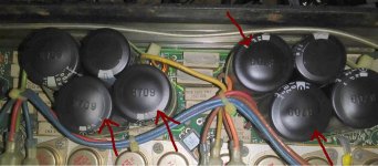
Bulging Capacitors on QSC MX1500
- By JaneyBleep
- PA Systems
- 32 Replies
I just got a hold of a QSC MX1500 Power Amplifier from a local bar at a great price.
Upon opening the cover to clean it ,the capacitors look like they are bulging at the top.
Should i replace them ?
I was listening to it for at least 5 hours before i opened it and sounds really good .
It wasn't getting hot or smelling like smoke .
Thank You
Upon opening the cover to clean it ,the capacitors look like they are bulging at the top.
Should i replace them ?
I was listening to it for at least 5 hours before i opened it and sounds really good .
It wasn't getting hot or smelling like smoke .
Thank You
Attachments
Tannoy System 15 DMT II
Hi Guys,
After some questions about designing a enclosure for the tannoy 3836 (3833)
I decided to “keep it simple” and just use the system 15 DMT II design.
Here’s the problem.
I downloaded the normal manual and the “Operating and Servive Manual” of the Tannoy monitor series.
The normal manual states the system 15 DMT II has a cabinet of 140 litre.
In the “Operating and Servive Manual” it’s 100 Litre !
(outer demensions are the same)
Since the cabinet demensions and the thickness of the used materials for front, back, top, bottom and sides are also described i can safely conclude there is a fault in the the “Operating and Servive Manual”.
(if i take of the size of the panels, it’s 149,5 liter. Then the bracing etc. So i think the 140 litre in the normal manual is correct.)
My question,
The “Operating and Servive Manual” says the system 15 DMT II uses 110 OD x 250mm port tubes.
OD i assume is outer diameter.
Can someone that has these speakers confirm the exact demensions?
Maybe meassure the diameter and length of the port tubes?
Cheers!
For Sale Caintuck Audio F-15 sapele magnum speaker pair
- By propitious
- Swap Meet
- 0 Replies
One pair of Caintuck Audio F-15 sapele magnum speakers. The drivers are Lii-Song F-15. The baffle is 1 1/2 inch thick sapele. You can read about them on the Caintuck Audio web page link to page The Lii 15 Baffle. On that page my speakers for sale are the second and third photos from the top. The attached photo shows the speakers I am selling at my home. Price is $875. They play plenty loud with a two watt tube amp. They disappear in my room with a wide and deep sound stage at eye level. To get the deepest bass, I recommend using a subwoofer like I do. You can read more about them on the web. You can listen to them in my home. I really have no way to ship them so you would have to pick them up in southern Indiana. I will consider meeting half way. PM me. They sound great, but I have too much stuff and have to make room.
Attachments
For Sale TI TPA3255EVM and MeanWell NES-350-48
- By strongbow60
- Swap Meet
- 0 Replies
Hi
As the heading already tells you I have a TI 3255EVM and A MeanWell 48V powersupply for sale.
I would prefer to sell it as a whole but parts can of course can be sold separately. I want to have 100€ for all of it. This includes the board where everything is mounted 🙂
Buyer pays postage and I only sell inside EU.
The EVM board has been upgraded with Elna Silmic caps on the input and also small bypass caps on the bigger power supply caps. These extra bypass caps had an obvious benefit on the sound reproduction, especially for voices. Of course, they can easily be removed.
NewClassD NCDV2 Singularity
Hi all,
has anyone here had experiences with these new NCD modules?
They look really well done, certainly not cheap, but still little compared to finished products of high-end audio jewelry Lol.
There is not much on the web, but if the final result was really good, compared to the other Class D modules available for DIYers, it could be really interesting.
Lu
Marantz ST-54 tuner unresponsive
- By lcsaszar
- Analogue Source
- 1 Replies
Hi all, this tuner works fine most of the time. The issue is with manual tuning. At the upper end of the FM band around 107 MHz sometimes it becomes unresponsive. When it happens I can't change frequency up or down, the only remedy is to turn it off and on. Then I can change frequency with auto scan or in manual steps again up to 108.0 MHz and it will fold over to 87.5 MHz as it should, it works in both directions... until it freezes again. It is a synthesized tuner. Could it be the prescaler chip at fault?
Schematics here:
https://www.electronica-pt.com/esquema/old-tv/marantz-vintage/marantz-st-54-schematics-31705/
Service info here:
https://archive.org/details/manual_ST54_MARANTZ
Schematics here:
https://www.electronica-pt.com/esquema/old-tv/marantz-vintage/marantz-st-54-schematics-31705/
Service info here:
https://archive.org/details/manual_ST54_MARANTZ
New horn/wave guide for midrange AMTs
- By vinylnvalves
- Multi-Way
- 6 Replies
I have previously ran a midrange AMT between 400hz and 7k in an OS rectangular horn, open at the back and have realised after trying it on a simple open baffle that I prefer the presentation of the horn. Whether it’s the directivity or the cardioid nature that the horn gives it don’t know. The horn was designed using the OS profile and super ellipses varying n=9 to n=4 to get the rectangular mouth and throat.


The horn measurements, offering so lower end boost. Since knocking up these temporary horns about 5 years ago, the only modification I have done is add an acoustic lens to break up the nasties you get from the horizontal bars , in the 2khz and 4khz range. So having watched the ATH thread with interest, I am wondering whether I can design a better horn? The mouth round off I did in CAD was just by eye.
So I am looking for advice, on the vertical and horizontal dispersion I used 60 degs and 90 previously, and whether there are any tricks that can improve the verticals.
WTB OPA2134 SMD x 2
Looking for a pair of OPA2134 in smd format. Out of stock everywhere I've looked in North America and not expected until later in 2023. Let me know if you have a pair you're willing to let go of. In Canada, but I have a mailbox in the US if necessary.
Thanks
Thanks
Exists Mid-Range with titanium cone
Hi, I would like to know if there is a mid-range speaker with a cone made of titanium?
driver compression test
hi, i have something to ask.
Are the tests and measurements that are done on compression loudspeakers always performed together with a horn or a waveguide? .
if this is the case then the result is the sum of the characteristics of the two elements.
Let's take for example this test:
https://audioxpress.com/article/test-bench-faital-pro-s-new-hf1460-pro-sound-compression-driver-1
The horn used is LTH142. but if I use for example a karlson K-tube, what are the characteristics that change?
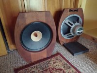
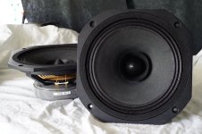
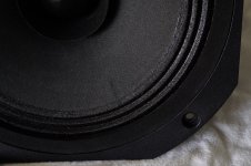
For Sale EMS LB8 MkII for sale
Hi,
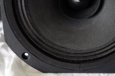
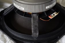
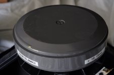
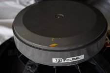
I´m selling a pair of used LB 8 MkII from EMS, France.
The drivers have a few optical marks and are optically not as new.
Technically perfect.
Basket voids have been filled with elastic damping material.
Price is 360€ for the pair, including shipment inside EU, and takes the visual imperfections into account.
All the best
Mattes
Attachments
-
 DSC06294.JPG778.3 KB · Views: 202
 -
 DSC06295.JPG508.8 KB · Views: 157
 -
 DSC06296.JPG581.6 KB · Views: 160
 -
 DSC06297.JPG319.4 KB · Views: 154
 -
 DSC06298.JPG170.8 KB · Views: 156
 -
 DSC06299.JPG151.4 KB · Views: 138
 -
 EMS LB8 MkII No.1 Rub and Buzz.jpg156 KB · Views: 147
 -
 EMS LB8 MkII No.2 Rub and Buzz.jpg155.5 KB · Views: 164
I'm a newbie. Need help with connecting my first Bluetooth Amplifier Board
- By berkal
- Construction Tips
- 4 Replies
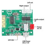
I recently purchased the Bluetooth 5.0 Amplifier Board Mini 5W*2 Stereo Power Amp Decoder Audio Module.
https://www.ebay.com.au/itm/195668964001
I purchase the following batteries:
Polymer Lithium Ion Battery LiPo 1100mAh 3.7V 603450 JST Connector
https://www.ebay.com.au/itm/133597363483
Polymer Lithium Ion Battery LiPo 500mAh 3.7V 702530 JST Connector
https://www.ebay.com.au/itm/175225850886
Both batteries separately connect to the red port with no issue but I don't get any power. I have tried charging with the Charging Micro USB Cable with no luck. I am able to get power to the board and connect to the Bluetooth when connecting the micro USB cable.
What am I doing wrong?
Attachments


DAC Setup in Daphile
- By TayyarBAcak
- PC Based
- 3 Replies
I use MX DAC with Daphile without any problem.
I am having problem when I connect T+A DAC (DAC 200). Namely: It recognizes T+A as the DAC used, but it appears as disabled and I cannot enable it.

I am having problem when I connect T+A DAC (DAC 200). Namely: It recognizes T+A as the DAC used, but it appears as disabled and I cannot enable it.
Hitachi HMA-9500 for parts
Hi,
I have a HMA-9500 where one of the mains transformers is missing. Anybody interested in parts, heatsink assemblies or whatever? I`m sure we can work out prices that will be acceptable. As I`m located in Norway, the heavy parts should preferably go to EU area.
Alternatively, does anybody have the right, as seen from the front, transformer?
R
18" woofer choice: Faital
- By youknowyou
- Multi-Way
- 35 Replies
hi everyone
my design will cosist of a 3 way, 1st order series xo
theres many Faital 18" woofer with smooth roll off and no serious peak up top, making many of their woofers suitable for my projects
question is, which is their best for low spl?
cheers and many thanks for all the help!
my design will cosist of a 3 way, 1st order series xo
theres many Faital 18" woofer with smooth roll off and no serious peak up top, making many of their woofers suitable for my projects
question is, which is their best for low spl?
cheers and many thanks for all the help!
Threshold SA 3.9e
- By spersanti276
- Solid State
- 14 Replies
Hello, is it possible to have the manual of this fantastic amp?
I am particularly worried about the possibility of driving the 3.9e from my Aleph P1.7 preamp in balanced mode, because I have read that the xlr input impedance of the power amp is only 600 ohm while in the P1.7 manual it is recommended to keep the master volume in the position of least attenuation (where it has the highest output impedance!).
I can't find anything on the web........
Thanks,
Stefano
Energy Pro 22 tweeter replacements ?
- By UserAbuser
- Multi-Way
- 27 Replies
Energy Pro 22 tweeter replacements, And now a crossover question.
Edit - Additional question at the bottom....
Yes I saw the other threads about this, but thought I'd ask (again) anyway 🙂
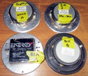
A friend has handed me 2 pairs of energy pro 22 speakers to repair.
One pair has original tweeters that are close to burnt out.
The tweeters measure ~7k ohm and have no output.
The other pair have mismatched tweeters.
One is the normal aluminium fascia, the other is a plastic fascia.
And just for fun, they neither measure or sound anything like each other.
Unless I am mistaken, if the voice coils are gone, then no one can repair it.
That's ABI Tech and Human Speakers.
Has there been any development in replacements or repairers since the older threads ?
My worst case scenario is to find a similar electrical match tweeter then graft that onto the old face plate followed by a little crossover tweaking.
Thoughts Comments Suggestions ?
------------------------------------------------------
Late edit - 5-4-2020 - Crossover question.
I have found a crossover schematic which shows the changes between the Pro 22 and the Reference 22.
I will add the sales brochure and schematic in a new post as I can't add it in on this post.
The changes are oh so subtle.
Looks like the reference version;
Raises the tweeter level half a db.
Lowers the bass drivers crossover and increases the roll off by a
minuscule amount.
Is this possibly a tweak to account for the port being moved to the front on the Reference version or is there another reason ?
(port is on the rear of the Pro, and the front on the Reference)
And yes I know it'll be pure speculation without the driver parameters for proper simulation. 🙂
Edit - Additional question at the bottom....
Yes I saw the other threads about this, but thought I'd ask (again) anyway 🙂
A friend has handed me 2 pairs of energy pro 22 speakers to repair.
One pair has original tweeters that are close to burnt out.
The tweeters measure ~7k ohm and have no output.
The other pair have mismatched tweeters.
One is the normal aluminium fascia, the other is a plastic fascia.
And just for fun, they neither measure or sound anything like each other.
Unless I am mistaken, if the voice coils are gone, then no one can repair it.
That's ABI Tech and Human Speakers.
Has there been any development in replacements or repairers since the older threads ?
My worst case scenario is to find a similar electrical match tweeter then graft that onto the old face plate followed by a little crossover tweaking.
Thoughts Comments Suggestions ?
------------------------------------------------------
Late edit - 5-4-2020 - Crossover question.
I have found a crossover schematic which shows the changes between the Pro 22 and the Reference 22.
I will add the sales brochure and schematic in a new post as I can't add it in on this post.
The changes are oh so subtle.
Looks like the reference version;
Raises the tweeter level half a db.
Lowers the bass drivers crossover and increases the roll off by a
minuscule amount.
Is this possibly a tweak to account for the port being moved to the front on the Reference version or is there another reason ?
(port is on the rear of the Pro, and the front on the Reference)
And yes I know it'll be pure speculation without the driver parameters for proper simulation. 🙂
Attachments
Klipsch K510, B&C DE750TN-16, Fastlane Eliptrac tweeters
I have for sale a single K510 horn and B&C DE750 along with a pair of Eliptrac K77 tweeter replacements with B&C DE10s from Fastlane audio. Asking $350.00 to be sold as a bundle am willing to trade for a power amp such as a Amp Camp Amp kit. Can be shipped, but probably going to run $30-$50 once packing materials are purchased. Shoot me a PM with any questions.
Fastlane tweeters have been sold
Pics coming shortly
Fastlane tweeters have been sold
Pics coming shortly
Nanodigi vs 2x4 HD
Hi,
I’m considering a minidsp, main purpose is for the subsonic filter and a low pass filter for subwoofer operation.
I don’t want the standard minidsp 2x4, because I don’t like the idea of ADC-processing-DAC, due to impact on sounds quality, even though I’m sure this will be fine for my purposes if used for the subwoofer only. I know that once I get my hands on one of these units, I’m going to enjoy playing with it, so want to future proof myself and consider putting HPF on my floor standing speakers (and trying eq’ing full range, more for fun, than for gain)
I’m therefore considering the minidsp 2x4 HD or the Nanodigi. I’d take a digital in, from various sources, USB from Laptop (my primary music listening source) and maybe a digital in from a TV.
My understanding is that the nanodigi has all the benefits of the 2x4 HD ?, just instead of analogue outs only, it has digital outs only. If this is the case, I’m tempted with the nanodigi, as I can take digital from sources, pass through nanadigi, one digital out straight to my hifi amplifier for driving floorstanders (even if straight pass through eg no eq). Then another digital out, through a higher quality (than minidsp 2x4HD) external DAC (maybe $100 DAC), over to the subwoofer.
This to me appears to be the best route for sound quality purposes, but so long as the nandigi has all the features of the minidsp 2x4 HD. My concern is it’s the minidsp 2x4 board and not the minidsp 2x4 HD inside a nanodigi. I’d like all the benefits of the minidsp 2x4 HD, including ability to upgrade to Dirac Live at later date.
Also, the nanodigi is specified with SPDIF outputs, so I can tie this into a Digital Coax Input on my hifi amplifier ?
Any comments or advice on the above would be appreciated.
Many thanks
martin
Audio Technology Flex Units 12" Woofers, Questions
I have been interested in AT's woofers, but from a customer's point of view they are very sparse about product details.
Regarding the 12D772510 KAP: Has anyone measured these? My questions are how high do they extend, at what frequency do they break up, and at what is their directionality like?
What advantage might be realized by the optional larger 220mm x 25mm F-size magnet?
The concept at this stage is, to pair a woofer with the Bliesma 74B-6 and RAAL 140-15DAM in 100L, possibly 20-25Hz tuning, mostly lower listening levels under 80dB at 3-4m distance. The crossover point for this woofer and the midrange may be around 500Hz or higher, and that depends as much on the woofer as the midrange.
Burnt my tweeters and i cant find a replacement part
- By Michael Kr
- Multi-Way
- 16 Replies
Hi everyone,
I Have had my hands on some M-AUDIO EX66 studio monitors for a while and i was recently listening to music and out of a sudden without any weird noise or anything like that the speakers were only playing mid and low frequencies, I tested the speakers on a tone generator 9000hz was the max that it could play and 10000hz only if i had the speakers loud enough
I Have been searching everywhere for replacement parts and i cant seem to find any, Can anyone suggest any tweeters that are as good as them or any solution to my probelm in general?
Any help would appreciated.
Speakers Specifications:
OPA1612AID Substitute
OPA1612AID's for the AMB Audio Behinger DCX2496 are on deep backorder from Mouser and Digikey. Is there another OPAMP that can be substituted and have the same performance.
NOTE: I realize I could stick just about any dual 8pin OPAMP in place but the goal here is high quality audio performace.
NOTE: I realize I could stick just about any dual 8pin OPAMP in place but the goal here is high quality audio performace.
Passive conversion to active
I’m sure this isn’t new but,
I want to experience an active system utilizing as much of the gear I already have as possible. I’ve got 3way hybrid speakers. The woofer is in a ported box with mid and tweeter on open baffle ( Dick Olsher designed Basszilla). I also have a Marantz Sr 7300 receiver (6 discrete channels). Why not add a MiniDSP and disconnect the passive networks and resupply the speakers directly from the dsp.
Bad idea? Doable? Ridiculous?
I do have additional amps that could be used, a Pass F6, and a pair of 300b monoblocks.
Helping Seniors Stay in their Homes
- By Fast Eddie D
- The Lounge
- 22 Replies
I heard this news item yesterday and it made me very happy.
https://wgntv.com/news/features/volunteers-help-repair-more-than-75-homes-in-chicagoland/
It's very common for home repairs and maintenance to get out of control for senior citizens. This can have some unfortunate consequences for the residents and also the community. Repairs can stack up and it's really expensive to get someone to come in and fix your house.
Volunteers went into houses in Englewood and did thousands of dollars of repairs and maintenance for free. All supplies are donated. Without this, I fear that many seniors would eventually be forced out of their homes.
This is how communities are supposed to work. I got some help fixing up my house as well as help with other issues I had. It made all the difference in the world to me. My health is much better and my quality of life is greatly improved. My only regret is that I didn't do more volunteer work when I was younger.
Paralleling two TDA7293 with balanced inputs
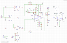
Schematics is attached.
Gain of the first stage is 1.1 and gain of the TDA chip is 10.
Any comments are appreciated!
Gain of the first stage is 1.1 and gain of the TDA chip is 10.
Any comments are appreciated!
Attachments
Help really needed, I can't prise driver out of PMC DB1 cabinet after removing all bolts
- By mojofilters
- Multi-Way
- 12 Replies
I thought I should start a new thread just for this specific issue, although it's obviously related to my ongoing attempt to source replacement drivers, contained in another thread.
I've successfully removed the 4 bolts (including their washers) holding in one LF driver, using the correctly sized metric Allen key as per PMC's own instructions.
Unfortunately the driver simply won't come out. I've tried using gravity, then all kinds of prising techniques, but it's just stuck fast!
I can't afford to cause damage, as I need to quickly put this driver in my other box. The other makes no noise at all, but after gluing up the worst tears in the first driver I'm trying to remove, it makes a passable sound.
Hence I want to check it in the other box, where the driver shows no physical damage and makes no noise at all. I want to ensure I have only blown that driver, rather that caused damage to the crossover as well/instead.
I'm trying to do this as quickly as possible, having found potential replacement drivers in Norway. I've managed to borrow a soldering iron for today, but it never occurred to me that I'd struggle to get the driver out of box after I've removed the Allen head bolts.
I'm really worried about causing damage, like I said I can't afford to break this driver any further, I really need what's left of it to test that it's just the driver in the other cabinet that's damaged, not the crossover. I also want to be able to buy these replacement drivers from Norway before someone else does, and I've only borrowed this soldering iron for tonight, expecting it to be an easy swap and test procedure.
For those unfamiliar with this cabinet, there's no access to the rear of the drivers due to the transmission line inside. Hence removing them from the front seems the only option. The help materials I managed to find all referred to much larger, PA sized type drivers, and the way this little 13cm one is built in seems quite different.
Help me diyaudio.com/community, you're my only hope!
TPA3116 (2x) board PS
- By Henk Haring
- Class D
- 4 Replies
Hi, i am running a small TPA 3116 stereo board with two TPA 3116 chips to feed my subwoofer (240 watt) on a 24 volt 4 amp universal notebook PS. Is this enough current or is it better to buy a switching supply 24 volt / 10 A. ? I am in dought if i get better bass performance with a stronger PS. Thanks for the input.
Feedback on Brandon3212276
Hi everyone:
I just completed a transaction with Brandon3212276. He was pleasant, polite
and super easy to work with. Payment was immediate, and he got back to me
quickly to let me know when the goods arrived in good condition.
I would definitely do business with Brandon3212276 again.
Thanks.
I just completed a transaction with Brandon3212276. He was pleasant, polite
and super easy to work with. Payment was immediate, and he got back to me
quickly to let me know when the goods arrived in good condition.
I would definitely do business with Brandon3212276 again.
Thanks.
Would someone please remind me where swap meet reviews are?
Hi:
Just did a very pleasant transaction with someone from the Swap Meet section and would like to leave a review and have them leave one for me.
I swear there was a review section here somewhere, but I've looked and looked and can't find it.
Can someone please tell me where it is?
Thanks.
Just did a very pleasant transaction with someone from the Swap Meet section and would like to leave a review and have them leave one for me.
I swear there was a review section here somewhere, but I've looked and looked and can't find it.
Can someone please tell me where it is?
Thanks.
Morel MW 144 based loudspeakers!
Hello dear friends 🙂
I recently got (almost as present) four (4pcs) brand new MW144 drivers from my friend.
Now i am eager to build some sweet D'apolito book shelf or florstanders, BR or compression or TL. No matter what kind but to be sweet reproducers 😉
Would buy two Morel tweeters for project.
Is there any plans for such a nice soeakers?
I am willing to pay for such plan if in egsistance 🙂
Best regards to all diyers outhere!
Yours truly
OberonGT
LinearSystems LSK389 compliment to the Toshiba 2SJ109?
Hello dear community,
I own some original Toshiba 2SJ109 because I wanted to build the AlephJ.
Now I'm interested in JeffDeGaar's Up-Amp...
The LSK389 is currently available from LinarSystems, can I use this as a compliment to the 2SJ109 and these differential amplifiers according to Papas Susy?
Thank you for your help!
Best regards
Mike
Why this constant upgrading?
- By celef
- Everything Else
- 81 Replies
I keep reading about new products in hifi magazines and wonders if new products really is better then older ones, to me majority of the products seems to go sideways and not forward, why would anyone be interested in buying a product that is not better then the last one? Like cables, how much better can a new cable be then your good old cable?
JBL 4344 MK 2 volume of 2123 internal enclosure
- By Bruderkuss
- Multi-Way
- 1 Replies
Hi,I would like to build a 4344 clone. As I have 2123 middriver I wonder which would be the right size of internal enclosure and how to stuff it.
Clone will be more like 4344 Mk 1, only the middriver will be 2123. I will use digital crossover + lm3886 amps.
best regards
mike
Clone will be more like 4344 Mk 1, only the middriver will be 2123. I will use digital crossover + lm3886 amps.
best regards
mike
REcapping Sansui AU5900
- By fjadouce100
- Solid State
- 5 Replies
I am planning to recap my recently acquired AU5900, starting with signal path caps and the 2 big power caps.
1. What do you recommend for caps in the signal path?
2. What good 2x 15000uF brand is recommended (without breaking the bank)
3. Will someone kindly list or encircle the caps in the signal path on the schematics ( from HIFI engine), as I am a bit confused about the signal path ( as it is not traced as in MArantz schematics)...I am not a technician, but I understand basic electronics and have soldering skills.
For Sale LR Phono PMillet (premium parts)
Up for sale is never used LR phono total assambled with premium parts.
I have decided not to install it as I have another phono wich I am very pleased with.
So here is your chance to get an easy ticket for an LR RIAA phono. The board is fully populated.
For fully working phono you need an psu or 2x 12V SLA battery and a small case + OPamps of your choice,
I will include NE5534 as I had in mind to use them instead of AD797.
If you want to buy just send me your offer and lets see...(for orientation the 4 x inductors cost 280 EURs)
Price: 300 EUR (eqv. in USD)
The item is located in SLovenia EU.

C3 and C6 are PSU caps will be soldered before shipping!
I have decided not to install it as I have another phono wich I am very pleased with.
So here is your chance to get an easy ticket for an LR RIAA phono. The board is fully populated.
For fully working phono you need an psu or 2x 12V SLA battery and a small case + OPamps of your choice,
I will include NE5534 as I had in mind to use them instead of AD797.
If you want to buy just send me your offer and lets see...(for orientation the 4 x inductors cost 280 EURs)
Price: 300 EUR (eqv. in USD)
The item is located in SLovenia EU.
C3 and C6 are PSU caps will be soldered before shipping!
-
Locked
TA2022 V 1.2 by LJM problems
- Chip Amps
- 2 Replies
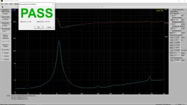
I have continous noises whistles that cuts the sound of music and after few seconds music start again, also one channel the tweeter sounds with a high frequency sound like frying eggs if I change the amp output terminal to speakers the sound change to the other channel, any help woul be really appreciate. Measured the gain with a dummy load & it's OK, also measured DC offset at the output terminals resulting near 0Vdc so both OK.
Login to view embedded media
Login to view embedded media
Login to view embedded media
Login to view embedded media
Electro Voice T25 mid and T350 tweeter
They need a little love. they sound great
T25$ 225$ mids and shipping for all four
answer to [ dustychi1@gmail.com
the T 350 tweeters need cosmetic work
T25$ 225$ mids and shipping for all four
answer to [ dustychi1@gmail.com
the T 350 tweeters need cosmetic work
Attachments

Retrofitting a 12V trigger in for Yamaha RX-V2400 receiver
- By loetkolben
- Solid State
- 14 Replies
Just wondering while trying to parse the schematics of my Yamaha RX-V2400 whether it would be possible to retrofit a 12V trigger input? It does not have one. Appreantly there are some variants of this model that came with a trigger input which makes me hopeful
If possible a solution that operates with standby power on/off vs. full.
I attached the schematics
If possible a solution that operates with standby power on/off vs. full.
I attached the schematics
Attachments
TubeLab SSE - Thermistor Part #
- By Tibetan
- Tubes / Valves
- 7 Replies
I'm working on finalizing my parts purchase list for the SSE board. Digging through some threads here it appears that an Amphenol CL-140: Digikey Part #KC014L-ND is the correct thermistor. Can someone confirm that please. Thanks.
Digikey - Thermistor
Digikey - Thermistor
Bruel & Kjaer 2619 service instructions,schematic
- By alexco
- Equipment & Tools
- 0 Replies
Service manual
Attachments
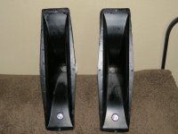
Beyma CP22 Membrane Flakes ???
I bought two nicely designed DIY PA Mid-High units which had served for a long time, both equipped with two Beyma CP22, and one EV1824M each, so six drivers all in all. 4 of these drivers were ok. Instead, both Beyma CP22 of one and the same cabinet had broken aluminium membranes. Broken membranes in a very strange way to me. They are broken into in a lot of small aluminium flakes.
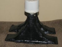
Both these two broken drivers stilll sound somehow (one expectedly flawed and the other quite miserably) when fed e.g. with white noise, so their voice coil is still intact, at approx. measured 7 Ohms. It seems strange to me that it's the inner part of the membrane which is badly "flaked", e.g. central to the voice coil, while the outer part of the membrane, e.g. peripheral from the voice coil, is ok less one spot on one driver where there is a single hole in it. The membranes are broken in kind of a "flaky" way. Very strange to me. Many of these mini aluminium flakes had then migrated to the periphery of the membrane where they got stuck on some glue leftovers.
The central parts of the flaked membrane is the part which is located under the central phase plug. Inside this phase plug, I discovered some quite sharp leftovers from the manufacturing process.
Can you help me to understand what happened to these two "flaked" tweeters?
Intact sample

Flaked samples


The one with the single hole in the outer section

One sample of a sharp manufacturing leftover under the phase plug

Both these two broken drivers stilll sound somehow (one expectedly flawed and the other quite miserably) when fed e.g. with white noise, so their voice coil is still intact, at approx. measured 7 Ohms. It seems strange to me that it's the inner part of the membrane which is badly "flaked", e.g. central to the voice coil, while the outer part of the membrane, e.g. peripheral from the voice coil, is ok less one spot on one driver where there is a single hole in it. The membranes are broken in kind of a "flaky" way. Very strange to me. Many of these mini aluminium flakes had then migrated to the periphery of the membrane where they got stuck on some glue leftovers.
The central parts of the flaked membrane is the part which is located under the central phase plug. Inside this phase plug, I discovered some quite sharp leftovers from the manufacturing process.
Can you help me to understand what happened to these two "flaked" tweeters?
Intact sample
Flaked samples
The one with the single hole in the outer section
One sample of a sharp manufacturing leftover under the phase plug
Repair of Polk woofer
I know this may not be the right place but I had a cone suck in and get stuck and was wondering what the next step is there floor starting polks the bottom speaker is the one that's sucked in
Attachments
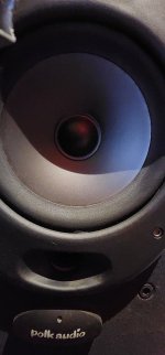
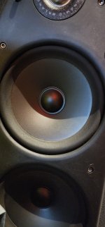
DELICA Model 1001 Tube tester
- By adam2a3
- Equipment & Tools
- 0 Replies
Hi everyone,
I recently aquired the DELICA Model 1001 tube tester, (made in Japan). I am looking for any available info, like Tube Data list.
I recently aquired the DELICA Model 1001 tube tester, (made in Japan). I am looking for any available info, like Tube Data list.
Weird diode failure
I am currently building a HV supply (+/-5kV)
As usual, the debugging process has been littered with various mishaps, like probe slips, etc.
Nothing exceptional, and I had installed spark-gaps and others measures in case things went wrong (which they did, big time).
Despite all my precautions, the regulation was lost, resulting in voltages well over 5kV appearing in unexpected places, causing arcing everywhere.
Since the bypass caps are 10nF, the discharges were severe, and when I tried to restore the circuit, I noticed anomalies: some diodes used for function selection were damaged, low-impedance as expected, but anomalies remained.
In the end, I resorted to test them all thoroughly, and I noticed that one of the 1N4148 had gone completely open: no leakage or conduction in any direct way.
Basically, it was completely open, which is exceptional for a diode having a whiskerless construction. It is a Telefunken device, completely ordinary, and it showed no external damage.
Such diodes normally fail short, or disintegrate completely, which was not the case here.
I lost quite an amount of time trying to diagnose what was wrong, because I had never seen such a behaviour before.
The moral is that anything can happen and will happen: never disregard even the the most unlikely possibilities. I lost a significant amount of time trying to figure out what was wrong, because I excluded the open possibility.
Diy balanced line level attenuator
- Construction Tips
- 0 Replies
I’m looking to build a unit with balanced XLR input and output that can attenuate the volume with a trs expression pedal jack. I would like the box to have a single knob on it as well to set a minimum volume. I know practically nothing about circuits, but from what I’ve been reading I think I wanna make it based on a vca so that the expression pedal is just a voltage divider and can be 20+ ft away from the unit within my rack. I’d like to be able to set the minimum volume so for example, I could make it -6db and control the volume from -6 to 0db remotely. I’d love to know if this is doable and if someone could help me with what parts / wiring could accomplish this. Thanks in advance!
My new 6216 design
- By astouffer
- Tubes / Valves
- 18 Replies
Hi all, here is something based on the 6216 pentode. It's an odd tube that nobody really seemed to notice. Datasheet for the curious. https://frank.pocnet.net/sheets/127/6/6216.pdf The advertised use was an active filter to replace an iron core choke. Pretty high heater current for only 10 watts dissipation. I used a 5670 because the chassis was from a previous project and the sockets were wired for the WE 407A, same tube but a 20v heater. Output iron is vintage Tamura and the power transformer is from a hifi chassis.
No pictures yet as I'm still tweaking the design. My chassis used octal output tubes so I'm sketching up some adapter plates so 9 pins can be mounted in their place. Going to get them laser cut from somewhere.
No pictures yet as I'm still tweaking the design. My chassis used octal output tubes so I'm sketching up some adapter plates so 9 pins can be mounted in their place. Going to get them laser cut from somewhere.
Attachments
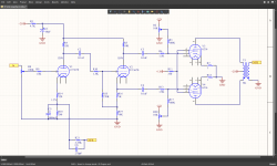
DJ-Mixer directly into 2 DSPs or DJ Mixer into compact Mixer first?
- By Johannes619
- PA Systems
- 8 Replies
Hello, what is the best way to connect a DJ-Mixer to a PA-System that uses 2 DSPs ?
I've been connection my gear as follows: DJ-Mixer -> Behringer Xenyx -> DSP -> speakers
Now I have the problem that I need to use 2 DSPs (a new 8 output dsp is coming, but its not coming in time)
I would do it as followed as I don't want the Behringer mixer in the chain because it doesn't have XLR outs:
DJ-Mixer -> XLR-y Split cable -> 2 DSPs. Can you do it like that? or should I buy something like the Allen Heath Zed6 to put in between the dj mixer and dsp.
I normally like the idea that I can control volume via an external mixer.
if I don't use an external mixer and plug the dj mixer right into the dsp I have no control over volume other than setting it so that when I max out the Mix1 Volume of the DJ mixer the pa is at max level. (DJ mixer is a xone92 btw)
Is it generally ok plugging a DJ mixer directly into the DSP? or should you use an external mixer like the Zed6 for gain and volume control in between the dj mixer and the dsp?
The 2A3 Tube Amplifier
- By CharlesArm
- Tubes / Valves
- 25 Replies
Hi!
Are you familiar with this project?
What can you say about it?
https://audioxpress.com/article/the-2a3-tube-amplifier-a-tribute-to-simplicity-and-warm-sound
Are you familiar with this project?
What can you say about it?
https://audioxpress.com/article/the-2a3-tube-amplifier-a-tribute-to-simplicity-and-warm-sound
The sound of 47Labs DAC clones
- By TheSoundMann
- Digital Line Level
- 29 Replies
What do they sound like? Do they often need further polishing?
Tannoy 3149g drivers pair
For dale a pair in good condition drivers from tannoy. They have fited new HE surrounds. Despite the age in verry good condition. Without crossovers, but I will give zhe buyer crossover plan that I have become directly from tannoy. Shipping no problem. Payment paypal or bank transfer. Price 500eu plus shipping.
Attachments
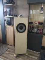
Yamaha CR-2020 suddenly stopped working
- By findog3103
- Solid State
- 3 Replies
Just turned on my integrated amp and it turns on but no sound. There was a brief very low sound of the record playing but then no sound. Changed speakers still nothing. Tried another amp and the speakers work. Headphone plug has no sound as well. All features light up but no sound. Help please.
Routing of Feedback from Output to LTP
- By kptseng
- Solid State
- 20 Replies
Hello Everyone,
I've been trying to work on PCB trace routing, and have been cracking my head on the route of the feedback from output back to LTP.
The plan is to have 2 layer PCB, with top layer for signal and power and bottom layer for signal star-ground and local decoupling 0v.
I also intend to use SMD resistors as much as I can.
I used to run traces under THT resistors, and feedback usually trace back to LTP "jumping" across the VAS stage through the feedback resistor. But with SMDs the gap between the 2 pads are just too small to put through any trace................ I usually use 1mm trace for signal.
My questions are:
1. Is it wrong to run the feedback trace on the bottom layer, meaning the feedback resistor will be mounted underneath, and it will cross the VAS on the top layer with a gap of 1.6mm (thickness of PCB)?
2. If this is ok, should the feedback resistor 10kR be closer to the LTP (after crossing the VAS), or closer to the output (before crossing the VAS)?
Would appreciate your thoughts, many thanks.
Car Amp turn on without Rem Terminal bridge to +12v
Hi, I've a class D car amp that was connected to battery charger and it worked fine with rem terminal attached to +12v to power on. Few days ago I notice that the amp powered on without rem terminal bridge to main +12v.
Any idea what that might be the cause? Amp works fine tho without rem connected to +12v.
Any idea what that might be the cause? Amp works fine tho without rem connected to +12v.
Audionote Soro
- By electricroo
- Tubes / Valves
- 3 Replies
Does anyone have an Audionote Soro SE. The version with the two resistors in the 6SL7 SRPP circuit where the feedback resistor and capacitor connect. Resistors R21 an R26 on the schematic. I'm interested in that particular circuit and am curious as to what Audionote used. Resistor value is not on the schematic that I have. The schematic is dated 29-01-03 (01/29/03).
Thank you
Thank you
Dolby 5.1 Receiver Ampflier | "Handmade" vs Commercial?
- By crinkled
- Everything Else
- 8 Replies
TLDR; I found these "handmade" amplifiers on youtube, are they any good when compared to the commercial ones?
I have been looking to get a Dolby 5.1 system for my house, and I've been looking all over for some solutions when I came across these "handmade" Dolby receiver amplifiers.
I do understand a little bit about electronics and audio but I'm no enthusiast by any means. So, when I saw these "handmade" amplifiers, that too at amazingly affordable prices (15,000INR to 25,000INR ~$200 to ~$300) I thought of going this route.
However, as did more research, I only got more confused. Would these "handmade" amplifiers be any good? I get that the commercial ones have standardized testing and QC to ensure quality, and I'm just not sure about these "handmade" products. They also sell the speaker units as a whole kit in some cases.
here are the youtube links (all show the amplifier internals)
Login to view embedded media Login to view embedded media Login to view embedded media Login to view embedded media
Tube Adapters
- By markw51
- Tubes / Valves
- 2 Replies
Ever try one of these EL84 to 6V6 adapters? Geared toward guitar players. How about for hifi?
https://www.amazon.com/VHT-AV-SP-AD...kills&sprefix=el84+to+,alexa-skills,89&sr=1-1
https://www.amazon.com/VHT-AV-SP-AD...kills&sprefix=el84+to+,alexa-skills,89&sr=1-1
-
Locked
Short list of high end class A/B amplifiers
- By mr_jj
- Solid State
- 46 Replies
I'm looking for ideas for building my own solid state class A/B amplifier, which should be meet the following specifications:
- Class A/B design
- Capable of delivering 50W rms into 8 ohms.
- I don't care if it is based on MOSFETs or BJTs, although I do have a slight preference for MOSFETs. The main thing is the performance.
- Exceptional THD performance up to maximum power levels over the audio frequency range.
- I don't care how complicated it is since I'm a professional electronics engineer. But I believe things should be no more complicated than they need to be.
TDA PCB Take a look
Hi, I was making myself a PCB for TDA7375 ( original from old Blaupunkt car radio ), anyway.
I was wondering if my GND is good or it is a ground-loop . Please take a look.
Also what resistor value to use for bridging the signal and power grounds?.
I was wondering if my GND is good or it is a ground-loop . Please take a look.
Also what resistor value to use for bridging the signal and power grounds?.
Attachments
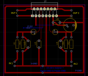
Classic Aleph Amplifier for Modern UMS Chassis
- By rhthatcher
- Pass Labs
- 143 Replies
This thread is for bringing back a classic with a modern twist.
Recently I rebuilt a pair of Rawson Aleph 5 monoblocks and the sound took me right back to the Aleph 3 I bought 15 or so years ago. That was my first Pass amp, and it was glorious. Since I fired those A5’s up I knew I needed to make a classic Aleph amp. Every day after shipping the A5's to their owner I craved that Aleph sound. Thinking back – why did I sell that Aleph 3? It’s the one that got away. It’s why I’m on this forum. As always, Blame Pa, right? And a big THANK YOU to Pa for the green light on this!
Right after the A5’s I was working on the layout for Aleph 2 front end boards and MOSFET Daughter boards. I also got to talking with Jim "6L6" about the classic Aleph circuit. We discussed the concept of a single board Aleph with some options… Some brainstorming brought this concept forward:
I started with the Aleph 30 schematic and added some updates based on DIYAudio threads over the years:
I built a prototype pair of Aleph 30 monoblocks last weekend for testing, using the 2SJ313's in the front end. The amps sound fantastic, as expected. Very authoritative lows with beautiful mids and highs. These went into a pair of monos that I rebuilt a few years ago. They had 20V donuts, not 18V – close enough.
During the build, I noted changes that would make the next rev more user-friendly. Most changes were to pads and details on the silkscreen. Those changes are done in a new revision. The built boards are my V0.0c Prototypes. The render of V0.0d will become V1.0a
Highlights of the changes on the new revision include:
C5, C9, C10 (220uF) updated footprints with 5.0 and 7.5mm LS pads
Updated C6, C7, C8 footprints for 5.0, 7.5, 10mm LS pads.
Updated silkscreens details on PCB: V+, V- , Output/Current Source, etc
Add AC Gain Test Jumper
Changed ZTX450 footprints - spaced out and larger pads
Updated trimpot footprints for triangle / straight line pins
Updated pads on most component footprints to be larger
Added part designators / IDs on silkscreen so they can be seen when parts are populated
Moved power MOSFET positions with respect to UMS - moved inboard.
Updated daughter board connections
I’ll make a run of these updated boards with a group buy if there is interest. I’ll follow up with details of BOM, AC Gain setting notes, build notes, etc.
To-do – does anyone want to chip in?
Build Notes at Post #72
https://www.diyaudio.com/community/...er-for-modern-ums-chassis.379571/post-6874343
Recently I rebuilt a pair of Rawson Aleph 5 monoblocks and the sound took me right back to the Aleph 3 I bought 15 or so years ago. That was my first Pass amp, and it was glorious. Since I fired those A5’s up I knew I needed to make a classic Aleph amp. Every day after shipping the A5's to their owner I craved that Aleph sound. Thinking back – why did I sell that Aleph 3? It’s the one that got away. It’s why I’m on this forum. As always, Blame Pa, right? And a big THANK YOU to Pa for the green light on this!
Right after the A5’s I was working on the layout for Aleph 2 front end boards and MOSFET Daughter boards. I also got to talking with Jim "6L6" about the classic Aleph circuit. We discussed the concept of a single board Aleph with some options… Some brainstorming brought this concept forward:
- Build a Classic Aleph circuit on a PCB for UMS heatsinks – Front End + Outputs & Current Sources
- Make it Flexible / Expandable - the "Swiss Knife Aleph". Include the ability to add additional PCB(s) for more semis. Want an Aleph 3/30? How about a 5/60? Got enough heatsinks for an Aleph 2? Want to try an Aleph 40? Be the first in your town to make the Aleph 1 million? The base PCB will handle 4 output and 4 current source MOSFETS, add board(s) as needed.
I started with the Aleph 30 schematic and added some updates based on DIYAudio threads over the years:
- Aleph Reloaded: 2SJ313 optional / updated R13 https://www.diyaudio.com/forums/pass-labs/267857-aleph-design-reloaded.html
- Bypass cap by zener Z5
- Added some trimpots for tweaking, added a jumper for AC Gain test (newest PCB rev)
- Added SE Only jumper by inputs – a tip of the hat to CSample on his F1 boards for that idea.
- Added an additional pair of MOSFETs on the base PCB
I built a prototype pair of Aleph 30 monoblocks last weekend for testing, using the 2SJ313's in the front end. The amps sound fantastic, as expected. Very authoritative lows with beautiful mids and highs. These went into a pair of monos that I rebuilt a few years ago. They had 20V donuts, not 18V – close enough.
During the build, I noted changes that would make the next rev more user-friendly. Most changes were to pads and details on the silkscreen. Those changes are done in a new revision. The built boards are my V0.0c Prototypes. The render of V0.0d will become V1.0a
Highlights of the changes on the new revision include:
C5, C9, C10 (220uF) updated footprints with 5.0 and 7.5mm LS pads
Updated C6, C7, C8 footprints for 5.0, 7.5, 10mm LS pads.
Updated silkscreens details on PCB: V+, V- , Output/Current Source, etc
Add AC Gain Test Jumper
Changed ZTX450 footprints - spaced out and larger pads
Updated trimpot footprints for triangle / straight line pins
Updated pads on most component footprints to be larger
Added part designators / IDs on silkscreen so they can be seen when parts are populated
Moved power MOSFET positions with respect to UMS - moved inboard.
Updated daughter board connections
I’ll make a run of these updated boards with a group buy if there is interest. I’ll follow up with details of BOM, AC Gain setting notes, build notes, etc.
To-do – does anyone want to chip in?
- Figure out any changes of component values for “Aleph 40” using 4 up/4down MOSFETs on a single PCB. What rail voltage? What resistors need to change? Anything else?
- Build Aleph5/60 or Aleph 2 with 2PCB’s per channel. The connection points are there. Populate the front end on one board and spread the MOSFETs on the 2 PCBs. I thought of making UMS compliant extension/daughterboards with 3up/3down or 6up/6down MOSFETS, and 6L6 asked “why not just use the same board without the front end?” Does anyone care to beta test it?
- Who will make a “Turbo” version?
Build Notes at Post #72
https://www.diyaudio.com/community/...er-for-modern-ums-chassis.379571/post-6874343
Attachments
-
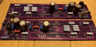 A30+ Proto V0.0c partially built.jpg546.7 KB · Views: 2,269
 -
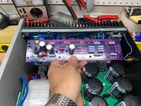 A30+ Proto V0.0c UMS Check.jpg829.9 KB · Views: 1,783
 -
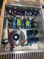 A30+ Proto V0.0c under test.jpg884.2 KB · Views: 1,676
 -
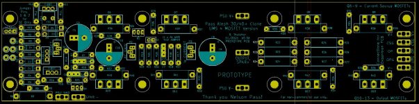 Aleph 30+ Layout No Copper V0.0d.JPG126.5 KB · Views: 1,689
 -
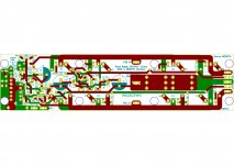 Aleph 30+ Layout With Copper V0.0d.jpg693.4 KB · Views: 1,593
 -
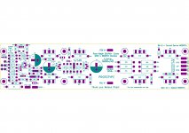 Aleph 30+ No Copper V0.0d.jpg598.6 KB · Views: 1,633
 -
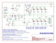 Aleph 30+ Schematic Prototype V0.0d.jpg962.2 KB · Views: 2,775
 -
Aleph 30+ Schematic Prototype V0.0d.pdf65.4 KB · Views: 551
Rotary Switch
Hey folks, I need some advise on the use of a rotary switch...
I have an amp that uses a rotary switch to change the output transformers different taps (ohms). What brand(s) are you all recommending for this type of switch. Being that the signal goes through the switch, I'm thinking it should of decent quality.
Thanks in advance...
Stacey
I have an amp that uses a rotary switch to change the output transformers different taps (ohms). What brand(s) are you all recommending for this type of switch. Being that the signal goes through the switch, I'm thinking it should of decent quality.
Thanks in advance...
Stacey
Load more
Projects by fanatics, for fanatics
Get answers and advice for everyone wanting to learn the art of audio.
Join the Community
507,689
Members
7,884,368
Messages