Hello !
Here is my first post about my recent work around speaker building.
This forum has been a great source of learning for this project, I guess it's the right thing to do to show you the actual results !
This project began with the aim of building a speaker system for listening sessions in various locations around my home. The brief was for something that sounded good, big, within a manageable budget and with DSP capabilities to adapt to a wide range of different listening conditions.
So it's a project conceived at the crossroads of Hifi and PA philosophies.
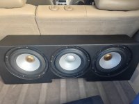
This being my first loudspeaker manufacturing project, I turned to the well-known recipe of a 15’ BR in a large box (135L), with externalised compression and its horn. For obvious design and manufacturing reasons.
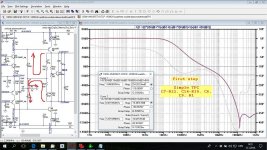
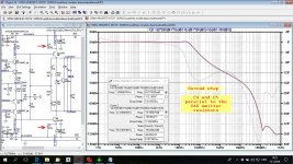
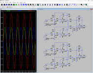
The choice of a DSP also led me towards an active crossover. This led me towards multi-amplification.
Here's the list of components:
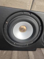
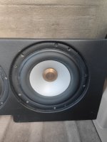
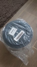
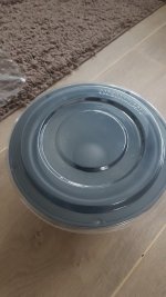
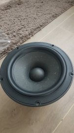
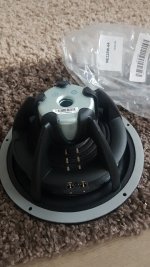
15‘’ Faital Pro 15PR400
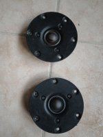
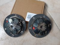
2‘’ Beyma CP750Ti
B&C ME60
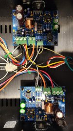
Behind the scene:
DBX DriveRack PA2
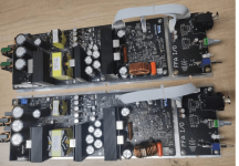
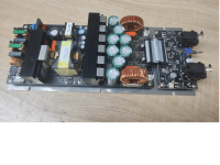
Crown XLS 2002 (for the tops)
Crown XLS 2502
The project is currently at the end of its first phase, and there's still work to be done. For example, the horn is due to be replaced, along with a potentially better tuning of the port, and a fair amount of cosmetic finishing.
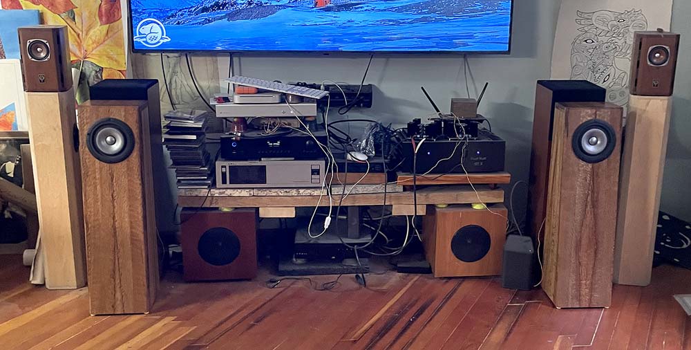
The system is currently located in my living room, which is not particularly practical for listening at correct volumes and which has some modal resonance problems. When the warm weather arrives, I'll do a series of outdoor measurements, which I'll post here if you're interested!
For the moment, and after several weeks of critical listening, I'm happy with the result as a first project, although I'm not reinventing the wheel, this simple system ticks most of the boxes in the desired specifications.
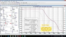
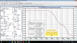
My first criticism would be that the vent perhaps deserves better tuning. Although I've followed the measurements given by WinISD, I feel there's more to be done. Fortunately, I've made sure that the vent can be modified more or less easily.
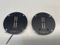
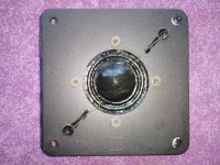
Although the compression is effective in its frequency ranges and pleasant, I'm missing quite a bit of information beyond 10kHz, or even lower. That's why I'd like to add a remote tweeter, (Fostex T90A, Visaton TL16H etc), with its share of questions, but we'll certainly have the opportunity to discuss them!
There's still some work to be done on the insulation, but after several tests with different materials, 45mm cotton panel glued on the internal sides and lower back panel seems to be giving the best results for the moment.
The ME60 horns were chosen temporarily to start listening, but are due to be replaced. Not having had the opportunity to make comparisons with other horns, my criticism is limited for the moment. I'd love to produce my own horns, and that will probably be the subject of another dedicated post.
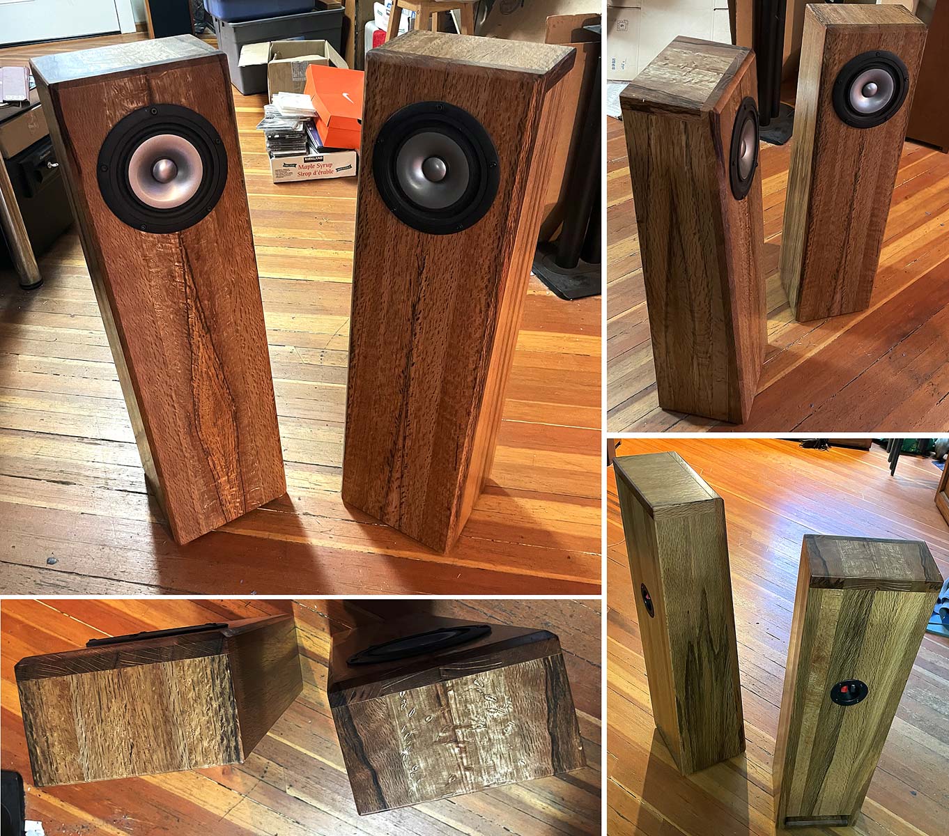
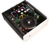
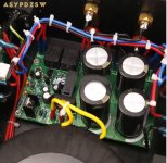
Here are few pictures of the fabrication:
Feel free to ask for details about the design, or even the plans! One of the goals of this project is to provide everything needed for anyone who wants to build it themselves and improve upon it!