Do you have a favorite driver that you would like to use in a mass loaded transmission line (MLTL) like a TABAQ, Pensil, or Metronome, but no one has yet run a simulation for it with MJK's software? Sometimes, folks on this forum can be very generous with their time and provide you a simulation if you ask. I have seen Bjohanessen do this many times for me and others. But in case you do not have the fortune of a full-blown simulation in MJK, but would like to hear what your driver sounds like in a MLTL, this thread is for you.
Let me first say that, this is not meant to replace a real simulation, but is rather an observation I have noticed that has worked a few times. I imagine that there are drivers where this will fail. For MLTL's where you want to push the tuning frequency below the natural free space frequency of the driver, choose a driver with a moderately high Qts (> 0.5).
This idea arose out of something I noticed happening on several occasions with a good result. I call it the 'accidental MLTL' technique because it may have been luck or chance but it seems to work a few times now for me (and at least once by others). I originally posted this in Bjohanessens's TABAQ thread but figured it was enough to spin off a new thread. I will repeat that post here...
If you happen to have MJK's MLTL worksheet, give this a try by running a simulation with your driver and running WinISD and calculating the CSA, length, and vent and compare the two. It would be interesting to hear your results.
----
Use WinISD bass reflex software (free) and plug in your driver's T/S params and design a vented bass reflex speaker enclosure using the default optimal case. That will give you the volume of the box and the vent cross sectional area and length.
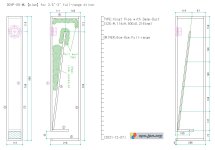
Now choose a maximum length you are willing to have based on practical size constraints, typically 30 inches to 40 inches long. This will correspond to a quarter wave length that is probably higher than the tuning freq of the bass reflex design that came out of WinISD (circa 60 to 75 Hz).
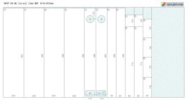
Calculate the cross sectional area (csa) of the transmission line using volume from WinISD and the length you set. If the csa is bigger than you prefer, you can go off the optimal case by going back to WinISD and adjusting the box volume manually to a smaller value and tweaking the frequency even. You can play with the vent to get it to a diam and length you like. Typically, I do this because the default vent is not very practical. Then use new box volume and vent dimensions to calculate the new csa based in length of the line again.
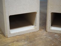
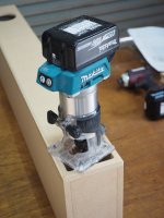
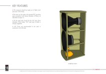
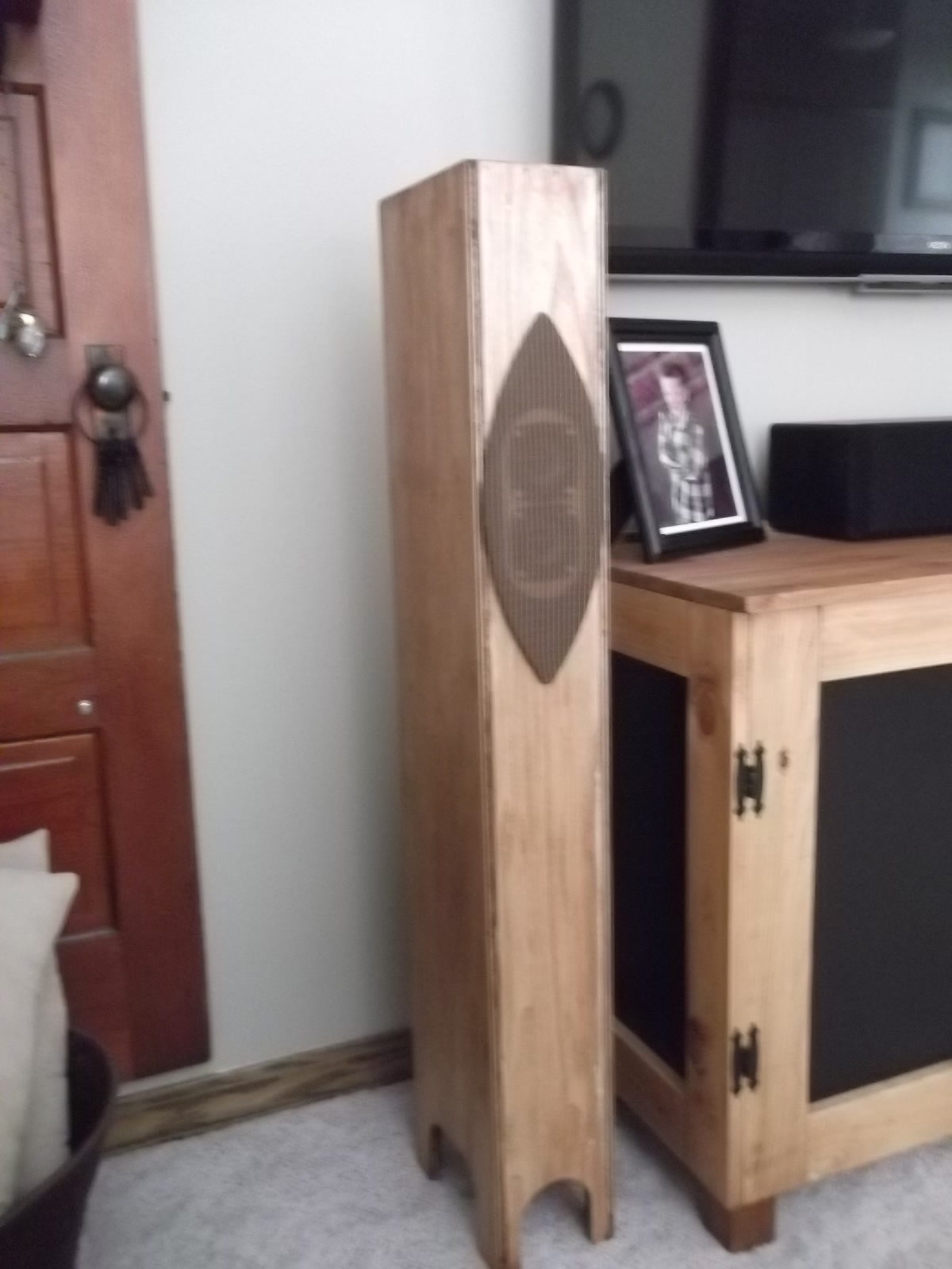
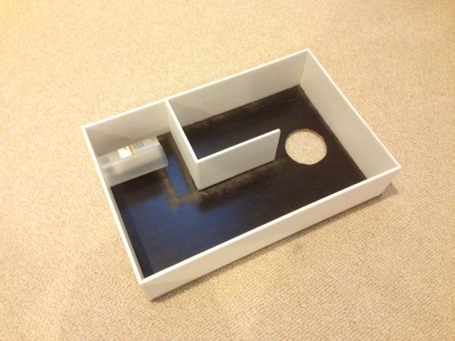
Now build the enclosure with the csa and length and put a vent with dimensions from WinISD at the distal end. On the closed end, measure 1/3 of distance down and make cutout for driver and mount it there. Put polyfill stuffing from closed end to about half to 2/3 of the way down the line. Adjust this to taste, less stuffing gets more boomy bass. More stuffing gets tighter bass at expense of amplitude. I have found that the position of the driver need not be exactly at 2/3 and indeed can even be at the closed end.
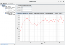
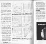
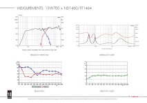
Doing this approach will guarantee that at worst, the speaker will perform as a bass reflex optimized for volume and vent size. But if physics of a MLTL and quarter wave theory kick in, you will end up with a speaker that has deeper bass extension than predicted by WinISD. The speakers that I have built following this recipe have measured very well when I look at what is coming from the bass port - typically, I get the low frequency extended or 'pulled down' by an additional 15 Hz from the plain bass reflex prediction. The speakers also sound great - very balanced when the bass port output integrates with the direct radiation from the driver.
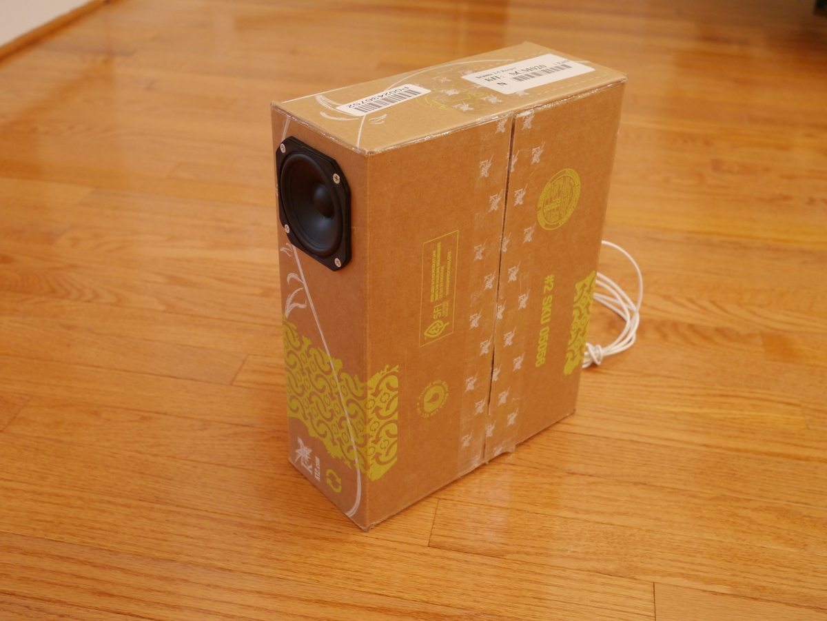
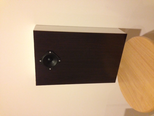
If you want to experiment without investing too much in wood, use foam core to build quick and dirty speaker. Even cardboard can be used as a test speaker for this.
----
Here are the two examples that have worked for me:
http://www.diyaudio.com/forums/full-range/223313-foam-core-board-speaker-enclosures-148.html
http://www.diyaudio.com/forums/full-range/223313-foam-core-board-speaker-enclosures-109.html
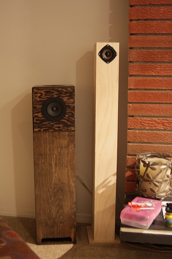
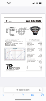
A third example not by me might be Cogitech's "nano tower" speaker with the ubiquitous TB W3-881si. Which I think was also designed as a bass reflex with WinISD but due to its slender aspect ratio and length, happens to have some very nice bass deeper than one would expect based on accounts from builders.
http://www.diyaudio.com/forums/full-range/200912-nanotower-tang-band-w3-881si.html
Update : 4th example is a quad driver bipole with W3-881si
http://www.diyaudio.com/forums/full-range/234535-tangband-w3-881-mltl-build.html
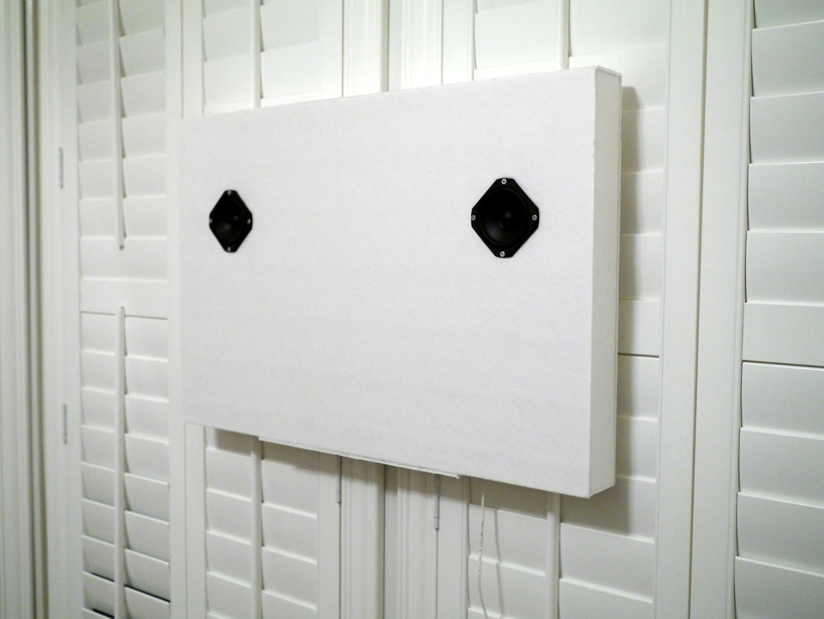
Fifth example is a folded AMLTL with a Vifa as wall or bookshelf speaker:
http://www.diyaudio.com/forums/full-range/231951-accidental-mltl-technique-16.html#post3466655