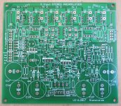
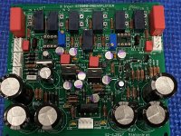
I have a few PCBs (as shown in photo) for the construction of a stereo Line preamplifier as was presented in my article in Audioxpress January 2019.
The preamplifier is based on OPA627 and has three unbalanced stereo inputs and two unbalanced stereo outputs.
Due to copy rights I cannot post the article here.
If someone has access to the article and want to build it, the price for each PCB is 28 Euros (shipping is included).
The preamplifier is based on OPA627 and has three unbalanced stereo inputs and two unbalanced stereo outputs.
Due to copy rights I cannot post the article here.
If someone has access to the article and want to build it, the price for each PCB is 28 Euros (shipping is included).
Attachments
Here are some more specifications for the Line Preamplifier:
- 3 unbalanced stereo Line inputs
- 2 unbalanced stereo outputs
- High quality relays on PCB are used for switching between the inputs
- ALPS potentiometer for the Volume
- Almost all of the preamplifier’s circuitry is contained on the PCB
- One OPA627 per channel is used.
- LT1763 and LT1964 low noise voltage regulators are used in the power supply
- Maximum gain of the preamplifier is 22 dB
- Separate power supply is used for the relays
- Turn-on delay and Mute circuit are included on the PCB
- Better than -70 dB crosstalk between channels at 1kHz
- Maximum output 6 Vrms at 600 Ω
I have purchased and built 2 of these boards with great results. I have paired one with an Aleph J power amp and the other with a refurbished Dynaco ST120A. I think they sound great through my ESS AMT-1 speakers from the late 1970's.
I did some rudimentary frequency response and harmonic distortion measurements with an HP signal generator, Tek oscilloscope and a Digilent Discovery 2 USB harmonic distortion analyzer. I didn't keep the data but I remember the output was flat way past the audio band with a 750 mV RMS signal, and the harmonic distortion was barely measurable.
I highly recommend these boards.
I’m definitely interested.
A search of Audioxpress found an article by George N. About a P3 preamp. If that is you, downloading the article results in a zip file that contains four files that each appear to only be the components list. No other information. I assume the article should also have contained power supply information, enclosure recommendations, etc.
Any ideas where I might be able to acquire the rest of the information?
Thanks,
Jeff
The article appears in Audioxpress January 2019, pages 58-65.
It has the tittle "The PR-3, A High quality stereo Preamplifier".
It has not posted on line and I am sorry but due to copy rights I cannot post the article here.
What you downloaded is only the Supplementary material for the article which includes the parts list.
If you could find the above issue you will have all the information.
I have purchased and built 2 of these boards with great results. I have paired one with an Aleph J power amp and the other with a refurbished Dynaco ST120A. I think they sound great through my ESS AMT-1 speakers from the late 1970's.
I did some rudimentary frequency response and harmonic distortion measurements with an HP signal generator, Tek oscilloscope and a Digilent Discovery 2 USB harmonic distortion analyzer. I didn't keep the data but I remember the output was flat way past the audio band with a 750 mV RMS signal, and the harmonic distortion was barely measurable.
I highly recommend these boards.
Any chance you could share info on your build? Power supply, enclosure, pictures maybe?
Thanks,
Jeff
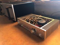
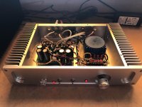
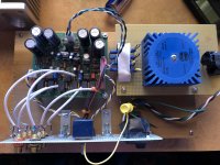
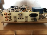
Here are pictures from my 2 builds. I did one on a breadboard and I paired it with a refurbished Dynaco ST120A. It is on my project list to put everything in a nice case. Maybe this spring.
I put the second in a chassis that I bought off Ebay and I use it with an Aleph J power amp. The case came with the heat sinks but they aren't needed.
For the power supply, you just need a transformer since the rectifier, filter caps and voltage regulators are on board. I used a Talema toroidal with dual 15VAC secondary windings.
There are 3 inputs to the board that get connected to the preamp input through a relay tree. I'm just using 2 of the inputs so I just have a channel 1 / channel 2 toggle switch, vs. a rotary 3 position switch.
These are high quality boards and the finished products sound great.
Attachments
Hi George,
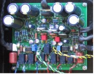
I finally received your preamp pcb and had time over the weekend to populate it. Unfortunately, I have to wait for a chassis now before I can get a listen
I couldn’t get the polystyrene caps, so I replaced them with Wima films.
Cheers!
I finally received your preamp pcb and had time over the weekend to populate it. Unfortunately, I have to wait for a chassis now before I can get a listen
I couldn’t get the polystyrene caps, so I replaced them with Wima films.
Cheers!
Attachments
Trying to order all the components before the pcb arrives, but having trouble confirming packaging.
Is everything through-hole or is there some surface mount? In particular the first line of caps, C1, C4, C15, etc. come in several different packages. Is there more detailed information somewhere other than the components list? The pictures in this thread help some but perhaps I should wait until the pcb arrives.
Thanks,
Jeff
Thanks, Vunce.
I did find your picture helpful, but looking at C1, C4 for example, your picture doesn’t show the mounting method obviously. They look like surface mount electrolytics but there are no pads on the bare pcb, just holes so I assume they are radial electrolytic cans. There are not any part numbers for the caps or resistors on the components list.
I’m sure once the board arrives I’ll be able to figure it out, but was hoping to get a jump on the components order.
BTW if you have a nice chassis suggestion, plus any other advice would be greatly appreciated.
Jeff
No prob Jeff!
Those are OS-CON polymer type caps:
https://www.mouser.com/ProductDetail/Panasonic/35SEPF22M/?qs=OE1iw1LrrPH%2BR6aZEdSlWA==
As for the chassis, I looked for a preamp “sized” case with two knobs. That was my criteria. Holes for inputs/outputs, LEDS and power switch I will machine.
Those are OS-CON polymer type caps:
https://www.mouser.com/ProductDetail/Panasonic/35SEPF22M/?qs=OE1iw1LrrPH%2BR6aZEdSlWA==
As for the chassis, I looked for a preamp “sized” case with two knobs. That was my criteria. Holes for inputs/outputs, LEDS and power switch I will machine.
Thanks again, Vunce.
While I have your ear, the bridge rectifier is speced at 1000V but only sees 15vac. Mouser won’t have 1000v units until May but have 800v units in stock. Need I wait or go to another supplier?
Also, I am pretty unfamiliar with LEDs. One size fits all given the dimension specs? And is the RLD3 2.4k resistor for the LEDs? Can’t find a RLD3 on the schematic, and no 2.4K resistors shown either.
Jeff