Dear DIY Audio Community,
In this thread I like to discuss a amplifier / speaker protection circuit that I designed.
Foreword:
I once fried a speaker by turning equipment on the wrong order.
As a countermeasure I improvised a circuit to delay speaker connection on power on.
So far so bad.
I like to get rid of the improvised delay circuit and have a real protection circuit instead.
There are a lot of modules available on the market, some even extremely cheap to buy.
I also found lots of circuits.
But none work the way I need them to.
My requirements for a speaker protection circuit:
1. Delayed connection of speaker after power on.
2. Instant speaker disconnection on power off.
3. Quick speaker disconnect in case of DC on amplifier output.
4. Latch relays off when any fault occurred.
5. Can be used for my dual mono design without hard wiring ground of the two amps together.
6. Can be built from parts I have at home or can source easily and cheap.
7. Is component selection invariant.
8. Is supply invariant from 12V to 24V.
9. Can be configured in a lot of ways so that others can make use of it easily.
From the circuits I found I liked the DIY Audio circuit best that is also used for the boards in the DIY Audio store.
It already fulfills requirements 6 and 7 and 8.
But this circuit has serious drawbacks I tried to get rid off.
I spent lots of time developing a circuit that hopefully does what I envisioned.
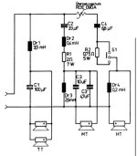
Circuit description:
The circuit has following modules:
1. AC to DC rectifier
2. Linear regulator
3. Relay status indicator
4. Turn on delay circuit
5. Latch circuit
6. DC detection
7. Instant off on AC loss
Module description in detail:
1. AC to DC
This is a standard rectifier. Nothing to explain.
2. Linear regulator
This is made up of discrete parts and a very basic circuit. I'm not sure whether this is a good design since I've never done any before and don't know the pitfalls. Feedback from the great engineers of the DIY community is very appreciated.
3. Relays status indicator
I used this circuit from the DIY Audio schematic. I find it a nice solution with the blinken light. Just tweaked component values to my needs. The LED blinks until the relays are engaged and then lights constantly.
4. Turn on delay circuit
I started with the DIY Audio schematic but added a Schmitt trigger for clearly defined switching of the relays because this was missing.
5. Latch circuit
A failure is a potentially catastrophic event. Should the speaker survive the first wave and the relays succeed to disconnect the speaker in time I don't like to give the disaster a second and third chance to ruin my speakers. This is why I designed this latch circuit to keep the relays disengaged after a fault occurred.
The latch is triggered by pulling the node called DC-DETECT to ground. So this can be triggered by any open collector output.
6. DC Detection
Again I used the DIY Audio circuit to start with but found it has two drawbacks:
First it is not sensitive enough. This may be intentional to avoid false error detection.
Second is that it can't detect simultaneous failure of both amps with one going positive and one going negative DC. Murphy will make that happen for sure especially since the DC event is a catastrophic failure condition and everything bad that is possible will happen here.
I also added resistors in the ground path to separate the two ground from each other. Hope this works as intended. For a stereo amplifier I recommend to leave R24 and R25 away and instead double the value of R22 and R23.
7. Instant off on AC loss
I found this circuit on the web and it does exactly what I need. Once the AC goes off the relays shall go off too quickly. There might be too much charge in the power supply capacitors that delay relay turn off. So the AC is sensed and makes the latch trigger once gone.
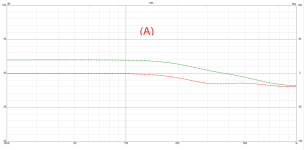
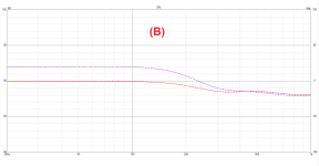
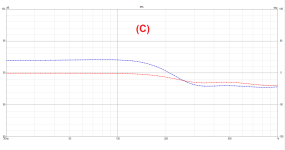
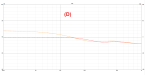
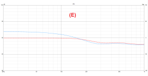
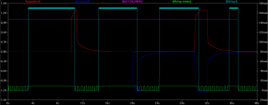
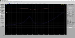
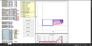
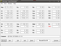
The circuit simulation shows that the circuit seems to behave the way I intended.
Turn off DC threshold is ~2V.
Relay turn off delay is ~70ms.
Please review the circuit and let me know your thoughts.
Did I get something totally wrong?
Do you have ideas to improve the circuit?
Thank you very much and best regards
Lee
Attachments:
- Schematic as PDF
- Schematic as LT Spice schematic
- Screenshot of operation with latch disabled to show every case that is covered
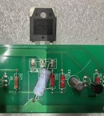


![20230716_213018[1].jpg](https://www.diyaudio.com/community/data/attachments/1101/1101692-94d897ce11fa165d58b25598de637975.jpg?hash=lNiXzhH6Fl "20230716_213018[1].jpg")