Seas FA22RCZ full range project

I have bought a pair of seas full range speakers. And now i hope
the good people in here will give me some input on what type of
cabinet is the best for this driver.
Should i go for a horn construction like Dallas or Jericho or a closed 60 L box
or 70L bass reflex box both the closed and the bass reflex boxes are found in the app notes from seas.

http://www.hasaudio.co.nz/images/SEAS/H1597-08_FA22RCZ_Datasheet.pdf
http://www.hasaudio.co.nz/images/SEAS/FA22RCZ_AppNote.pdf
An externally hosted image should be here but it was not working when we last tested it.

All sugestions are welcome in this prosess. I just hope i get a lot of ideas to try out.

Crossover for B&C reference design

Hi,
I built 4 coaxial speakers according to the B&C CX10.64 reference design. For initial testing, I bi-amped them. Completely blown away by the sound !!!

Next step is to build and install a crossover. Unfortunately, the information the B&C provides is limited to the schematic with component values. (see attachment)
I understand, of course, that they don't want to name brands here, but I get a little lost when searching for components.

Can you help me on my way with this. There is so much information that I can't see the forest for the trees.
I had already understood that low resistance coils (thick wire) and high voltage capacitors help reduce distortion.
But where is the sweet spot? The speaker in question is a coaxial type with 500W continuous power.

Also, I think it would be useful to use some kind of protection to protect the HF driver. But what?
Any other things I should pay attention to?

Thanks for your answers.

Regards,
Johan

Crossover CX10.64.png

DAC advice needed

Firstly, I know absolutely zero about DACs! So I would like advice on how to improve the performance of my system in subjective terms of ‘being there’ with - mainly - small scale classical music. I have a large collection of mainly older CDs.

My present CD set-up includes a TEAC T1 Transport (which is a troublesome thing) and a Philips 850MkII used for SPDI/F output only. My DAC is a SABBU - Second version. So any recommendations MUST have SPDI/F coax input. At my age I wish to spend less than a fortune and will consider Ready to Connect boards, good fully sorted used boards/units. Any used offers must be from UK/Eu.


[The rest comprises a well built Hypnotise pre, a Bonsai KX2 Power amp (Also a Bonsai first version NX, Joachim Gerhard ‘Sonics Allegretto’ speakers all connected with Yamamura Churchill
Ic and spkr. cables].

Being ‘beyond elderly’ (82 in 5 weeks) and have a very shaky right hand so only the simplest soldering is possible. I have a few useful chassis units suitable for boards and a few transformers, but would prefer a plug and play solution which will comfortably out-perform the SABBU.

Many thanks,

Brian
  • Like
Reactions: matsurus

The TO39-AMP (40 Output Transistor Fun Project)

Hello all,
may I introduce my newest build:
A power amplifier, only with TO39 metal can transistors (-> this project on my own page, in german)

Some month ago I got a large amount of old unused electronic parts.
Including many transistors in TO39 housing: BC140, BC160, BSX45; also many electrolytic capacitors of larger capacity: 4700uf etc ..
Too good to throw away, so what can you do with it?
I got the idea to build an amplifier with it and only use these TO39 transistors, even for the output devices.
Some might think that's nonsense, but it doesn't matter: here the thing is and it works.

amp1.jpg

After countless LTSpice simulation runs, I finally made the PCB layouts and had the boards made.
Since you always order several boards, I designed the layouts in such a way that the remaining boards could also be used for "normal" amplifiers, e.g. with TO126 and TO264, SOT-93 or similar transistors. For this reason, the TO39 output transistors sit on their own circuit board.
The capacitors in the parts convolut were all axial, so the power supply board has space for axial and radial smoothing capacitors.

pcb1.jpg pcb2.jpg

The power supply is regulated and offers a stable voltage of + 20V and -20V.
More is not possible for the amplifier, since the transistors BC140 / BC160 can only withstand 40V.
The supply contains an electronic fuse which switches off the operating voltage of the amplifier if a set current value is exceeded.
There is also an interface that enables the power supply unit to be shut down with an external switching voltage; this is e.g. used by the DC-Protection.

pwr_sup_1.jpg

The output transistors are sitting quite close together and have no heat sinks; with convection only they don't get rid of their heat, so a fan is required. Here, however, a very low air flow is sufficient, so that no annoyingly loud, powerful fan is necessary.

amp3.jpg
So the amplifier can continuously deliver 30 watts into 4 ohms (per channel) without unhealthy heating.
If someone misses the obligatory small coil at the output: it will later be on the DC protection board; but at the moment the Amp works without it, no problems.
Everything is fitted onto a PVC plate for the function test. The next goal is to make a suitable housing. And, consequently, to replace the SOT-93 series transistors in the power supply unit with the extra board with TO39 transistors.

Here are some more photos and oscillograms.

amp2.jpg amp4.JPG

output board assembly:
the resistors for the output transistors are fitted to the downside of the board.
after every new fitted transistor was tested, if they all work as one
assembly1.jpg assembly.jpg
(There are 7 PNPs, 8 NPNs on the main board, 20 PNP / NPNs each on the output board, a total of 55 transistors, per channel)


sinus 1000 Hz .......................sinus clipping 1000 Hz............rectangle 1000 Hz..................triangle 10000 Hz
(each with probe head 10:1)
sin_1k.jpg clipping_1000hz.jpg rect_1k.jpg triang_10k.jpg

-> this project on my own page, in german

What on earth have I done to my amp....

Amp: Audio Research D70 MkII

Background: I have been attempting to identify and replace resistors that are causing fuzzy output distortion. I have also disconnected the 16 and 4 ohm outputs, and wired a pair of modern binding posts to the 8 and 0 ohm outputs.

I discovered that somehow, the amp is now producing an upward curve starting around 1k and peaking at +4 dB at ~18k (see attached measurements, both channels). I have verified that this is not a problem with my measuring equipment by testing another amp. I'm taking measurements with a 7.5 ohm load resistor at 1v output level.

My first thought was that I screwed up a resistor value, but I've been careful about that, and I'm not necessarily replacing matching resistors on both channels if only one seemed bad, so how would I get identical behavior on both channels?

Second thought is that someone I crossed wires from the output transformer and created this effect? But I'm not sure how that would even work.

I'm on the verge of throwing it at my tech and having him pull my *** out of the fire, but I'd at least like to try fixing whatever I've done....

Attachments

Thorens TD160 plinth plans/dimensions

Hey all,

New member here about to take on a TD160 restoration project. I've scoured across the site and internet and have not found proper plans or dimensions for a new plinth.

I could take apart my TD160 and measure and all that but my wife's uncle is a woodworker and would enjoy building a new plinth but I would have to send him the dimensions/plans as he lives several hours away.

Any leads to help a guy out?

Thanks in advance.

Allen & Heath Zed-14 Pre-EQ modification

I recently purchased an Allen&Heath Zed-14 for a price that was too good to refuse. There is one thing about it that is a total non-starter for me, the pre-fade Auxes are Post EQ and Post insert. Given the lower price point of this model there are no internal jumpers to configure the options on these auxes. So, off to the service manuals.

I have a plan that needs a bit of critiquing. I have included the schematic for the Mixwizard set up for pre-eq aux, and traced the signal path.
I have also included the Zed, highlighted the stock signal pat,h and circled the components that see audio in red for stock, blue for modifications. There's a blue "X" where I plan to place the cut and a blue line where I plan to tap. My main concern is that when the highpass is not engaged, there appears to be no 47K pull-down resistor for C18.

Thoughts?
Chad

Attachments

  • Wz3_16_2 mono input markup.PNG
    Wz3_16_2 mono input markup.PNG
    172.2 KB · Views: 130
  • ZED14 mono input markup.PNG
    ZED14 mono input markup.PNG
    153.1 KB · Views: 182

ADC output noise in digital reverb circuit

Hi guys,
I’m trying to troubleshoot a noise issue in a digital reverb circuit that’s driving me nuts. Here’s the schematic. Hope you could
Give some advice, I don’t own an oscilloscope and this makes troubleshooting a pain.

I was able to trace down the noise to ADC U201 SDOUT. When shorted to ground, U202 DIN is also grounded and the noise stops.
Grounding U201 /RST resets U201 U202 and U203 and the noise goes away while grounded, but reappears once /RST is high again.
Grounding U201 AINL does not eliminate the noise , therefore I thought the problem was isolated to U201. Replaced it with another cs5340, but no luck. Also thought about this being a problem with the supervisor circuit u205, and replaced the stc809 with a mpc809t but still no luck.
Any ideas??
Thank you very much,
Fran

Attachments

  • IMG_8646.jpeg
    IMG_8646.jpeg
    142.8 KB · Views: 187
  • IMG_8647.jpeg
    IMG_8647.jpeg
    136.7 KB · Views: 155

Using online UPS to power a system

Setting up a system I will use for a small festival I arrange annually, and have been thinking a bit about the power situation. Typically I will rent a 20-40kVA trailer but both the cost and efficiency is not that great.
As I understand when it comes to generator power you can not treat it as a normal outlet where if for example you have a outlet that is fused at 16A, you will have excess power for peaks on top of that. So that is why for example my sub amp, a Morin x-1304 rated to output up to 4x7380w, can be connected with a regular schuko plug. The average consumption will be about 1/8 of the peak assuming a crest factor of 9dB and pushing it just into clip, resulting in a actual draw of 3690w. Surely it is pushing it to run the amp att full load on all channels in 2 ohm, but in theory possible.
Now with a generator you will not have the extra peak capacity. If the generator can deliver 20kVA that is typically some 5-7kW per phase, leaving very little headroom.
The 40KvA trailer is great and provides really nice stable power and gives resonable headroom, but it does cost quite a bit to rent and run.

So, the frustrating part is that it seems like in reality I would not need such a large generator. If I just had enough capacitance, it only needs to provide enough for the average consumption. So for example with my current system the speakers are rated to around 10500W RMS. Assuming extremely compressed music with a 6dB crest that gives 5250w draw. In reality I would probably be down a DB or so from max and normally play music with 7-8dB crest, giving around 2625w actual draw.
So rather than renting a machine that delivers many times more than I need, can I not add a buffer between generator and amps to handle the peaks and instead run a much smaller generator?

Perhaps a large inverter generator like a 7kW Honda will actually provide enough peak power, but seems to only exists single phase versions, do get very expensive and hard to find for rental in the area.

One solution would be an online double conversion UPS. Those used to be very expensive, especially if they should be able to handle these kind of power levels, but looking at Alibaba there are some units below €1000 with shipping that can deliver over 10kW on 3 phases with a 3:1 crest factor according to the specs. Add some €500 LifeoPO4 cells having great capacity for momentary discharge, and it seems like I could build a little wagon to act as buffer between generator and system ensuring smooth constant sine wave output with greatly increased peak capacity.

So add to that an old 3-phase 10kVA diesel for €500 or so, and then for around €2000 total have something that I would think will beat the €5000 Honda by far when it comes to how much peak power it can deliver.

I'm not that knowledgeable about electricity, and especially high voltage 3 phase, but seems quite doable with off the shelves products not requiring any expert knowledge, but can ask an electrician for advice if needed.

Is it a bad idea, and have I made any miscalculations or incorrect assumptions?

DIN rail /SMPS for audio

I have been wondering if a din rail/smps is a good option for an audio power supply. One that I have been looking at for 24 VDC output is the SDR series by Meanwell. The noise is a repectable 100mv @20MHz and with a filter should be able to be reduced. Is there any negatives with using a din rail system for audio? This is the link I was looking at https://www.bravoelectro.com/sdr-120-24.html
Thanks for comments.
MM

Passive filter attenuation of breakup-related distortion in a woofer

So it seems pretty well-established at this point that a parallel LCR in series with a driver (as opposed to a series LCR in parallel with a driver) can function to suppress any extra HD from the increased sensitivity around breakup (and, I guess, HD-driven IMD too).

But, can a typical passive low-pass filter do the exact same thing, e.g. 2nd order LR or 4th order LR, as long as the slope starts early enough that there is significant attenuation around the peak?

Ian Canada Purepi 3.3v no power output

I recently built a streamer consist of:
Purepi, Rpi4b, receiverpi ddc, amanero 384, fifopiq7, hdmipipro and Ucconditioner 3.3v. All the device are function ok, except the J2- 3.3v of purepi ;no power output. I have checked and tested the fuse, it is ok. I have set the S4 switch to off position (enable battery function). All the D11, D1,D13,D8, D10,D4 LED are lit, but the J2 - 3.3v still no power output. Is anybody facing the same problem? what could go wrong? From the photo, u can see no power output to the ucconditioner. Pls assist. Thank you.
20240226_212547.jpg

How to turn a dual mono F4 into a mono block?

Simple question,

I had a F4 built as a dual mono, two 230VA (if I recall correct) transformers to feed the whole thing, got proof 25W not enough to feed my speakers and I am sure if I sell those to buy more sensitive ones I won't buy again anything this big in size (and $$$) thought I might have another F4 built and use them as mono blocks, what would it take to convert the already made one into it?

Grazie

DIY HiFi PA 12” and matching subwoofer ..

For install in room 8x11 x3,5 meters about..

pro hf10ak with matching horn? What horn is best? Spaciality is important!! Think David Mancuso.. good components for crossover.. Mundorf, jentzen, etc aircoil if possible and needed

What is the best 12” driver?
Beyma
Bms
Faital
18sound
Lavoce
?

What software is best to calculate volume, shape, crossover? Would like to have passive crossover on subwoofer also? 18” ? Or 15” down to 30hz -3db I’m thinking?

Simple, old school? Decent kick..

Suggestion for design?

Thinking something like this..

IMG_0479.jpeg

IMG_0480.jpeg

DIY hifi Pa speakers and subwoofers with passive crossover..

For install in room 8x11 x3,5 meters about..

pro hf10ak with matching horn? What horn is best? Spaciality is important!! Think David Mancuso.. good components for crossover.. Mundorf, jentzen, etc aircoil if possible and needed

What is the best 12” driver?
Beyma
Bms
Faital
18sound
Lavoce
?

What software is best to calculate volume, shape, crossover? Would like to have passive crossover on subwoofer also? 18” ? Or 15” down to 30hz -3db I’m thinking?

Simple, old school? Decent kick..

Suggestion for design?

Thinking something like this for subs..

IMG_0480.jpeg

Attachments

  • IMG_0479.jpeg
    IMG_0479.jpeg
    166.6 KB · Views: 78

BRZHiFi PAT-A80 Filament Voltage Adjustment

I don’t mind saying that I love the sound of tube amps, but the volts inside them terrify me. I have a rudimentary understanding of how they work, but I am not DIY when it comes to construction. I prefer to leave that to the experts. But I recently bought some 'upgraded design' Chi-Fi mono 300B SET amps and something has thrown me…on the back of the units is a pot for regulating the filament voltage. All the manual has to say about this knob, translated from simplified Chinese, is: “Note: Filament voltage balance adjustment knob. Tube parameter discrepancy can be adjusted to improve signal-to-noise ratio.” I assume this pot adjusts the AC voltage on the 300B heater, and a bit of research suggests for the 300B this should be ~5V. It has been suggested that hum can be suppressed by adjusting the heater voltage. Am I on the right track? Should I play with these knobs (one on each channel) and let my ears do the adjustment? Or is this more about compensating for the mains supply voltage variation from 220VAC – the manual says “The power supply voltage must be within 5% of the specified voltage.”

I’ve got a DVM and was thinking about how I should measure this voltage. Should I power up the amp with the 5U4C rectifier and 6H8C input stage installed, but the 300B removed, and measure the voltage across pins 1 and 4, or is this dangerous? Alternatively, to measure under load (and fully up to operating temperature) I have considered wrapping some thin wire around pins 1 and 4 of the 300B before inserting them, and measuring the voltage in situ.

I don’t want to try any of this until someone tells me I’m a bloody idiot and should leave well alone, or otherwise…

Thanks, Rowan

looking for new - or old - dac chip

Hi all.
I love my pcm5102A based dac, i2soverusb, the non preringing filter, the dedicated power supply etc.
After bout 10 years i would like to explore other stuff, specifically what i missed in my build is the non ability to try different output stages.
Yes, i know that the specs are not so good and there are far better dacs out there, i don't mind.
I know it will be very difficult to find a better - to me - sounding dac in therms of rythm, pace, easy to listening, 3D etc.
But, 10 years are too much to stay, so could you suggest any chip that allows me to choose at least an iir low latency filter and that has a (dual) current output?
I'm really considering even the direct dsd route, but one doesn't exclude the other.
In the end, the nos multibit with deep 7th order lpf is not for me, I ended up to like the more detailed presentation of the delta sigma, but only when it is not too much "digital", this is what make me think it would be difficult to find an alternative.

Everyone has different tastes, of course.
This is good for us in the hobby.

Edit:
it is difficult to me to listen to very good dac, diy or not, so i have to follow my path.
A very good multibit build is not so easy to do, and i'm afraid to do so much work only to realize that i would need more "resolution".
Maybe i have to move for a listening first.
If anyone in Austria/Southern Germany would like to invite me to listen to a diy DAC, I would be happy to accept.
Pm me if it is the case.

Bit of help? PSU for DL-1656 CL m series Compressor/Limiter modules

Hey All,

Hope all is well,

I have 8 Calrec DL-1656 CL m series Compressor/Limiter modules racked.

When I purchased this unit, I brought it knowing that the PSU was not working, after inspecting the circuit board and the PSU I found SO MUCH mouse urine and fecies throughout everything. It had housed a few generations of mice.

So, I cleaned it all, there was slight corosion in places but nothing a cotton bud and some isopropyl couldn't solve.

After the deep clean, it fired up and everything was working perfectly.

Though, after a few months, it sporadically did the issue again, which I am under the assumption that the PSU is overloading the modules, as all the meters go full signal red, pass no signal and after powering it on and off and fiddling with the PSU, it comes good again.

The PSU is a calrec ams ZN2275 0I, I can't find anything online about it.

It has multiple DC outputs +8L, +16L, and -16L.

It has a 5 Pin DC O/P

PINs

1 -16A
2 - CR
3 - +16A
4 - OL
5 - +8L

Just wondering for powering these vintage modules what would be a modern option in order to replace it or if need be, how I'd go about making a custom PSU for them?

Ideally I'm looking to seperate these into 4 racks of 2 modules, does anyone have any recomendations on how to go about doing this project?

Hope someone can help, or point me in a direction that will help.

I have attached some images for reference.

Thanks!

Attachments

  • 426402273_6958170944294856_827628606183593688_n.jpg
    426402273_6958170944294856_827628606183593688_n.jpg
    110 KB · Views: 50
  • 430449643_25126044297009904_4330656112074868295_n.jpg
    430449643_25126044297009904_4330656112074868295_n.jpg
    96.6 KB · Views: 44
  • 430877707_8125356944157583_3741725823503184298_n.jpg
    430877707_8125356944157583_3741725823503184298_n.jpg
    74.4 KB · Views: 43
  • 431009314_25004160412563217_1920049113720173630_n.jpg
    431009314_25004160412563217_1920049113720173630_n.jpg
    156.5 KB · Views: 56

Piezo element to MIC level WITHOUT attenuating after an amp, how can I handle it?

So I'm tooling around with the idea of putting a bunch of cheap Piezos in guitars, specifically with the idea of using mic preamps to amplify the signal. I am absolutely aware that other amp\preamp solutions are much much better. This is for funsies\be different.

As I understand it, these "pickups" have an output that is slightly higher than a mic, but vastly different impedances as I understand it. Now I don't know the difference between "input and output" impedance or how any of that works which is why I'm reaching out for help.

There are "DI"s available for this, but from what I can tell, these are designed to take a signal that is being amplified from the source pickup, put through a preamp, and then attenuated back down to mic level. What I am looking to do is actually just go straight down to mic level and match the impedance. Basically I want a Neve or API to act as the preamp that comes immediately after the pedal. From what I gather, it might be possible to do this with just a couple chosen components and a cable.

Anyways, I'm having trouble getting information on this and understanding it, even though I'm fairly well versed in gain staging otherwise. Information of getting the pickup to designed amps to take it up to instrument level are abundant, but I have a different use case.

White whales ina pod, tube based personal portable

Hello all, first some background. In 1993, while in high school, I started my first job in KFC. With all that money that I never had before, I really wanted to first buy a really nice music system. I had already started DJ'ing and also performed Shabba Ranks lines on the mic. I was so ready to move on from my DJ rig in my bedroom. I started reading all the reviews in AU hi-fi mag and taking handfuls of Greensleeves sampler CDs to all the high-end shops around Sydney. Nothing really seemed to do the music justice. I used to have a portable with CD and cable to stick the headphone out to my PA. I took this to an op shop that carried a lot of secondhand electronics. There magic happened, a wooded cabinet for $10 sounded better than anything on York Street, Sydney. It had these huge speakers built in and a record player! And line in!! And mic in!!!

Needless to say, I saved a lot of money and bought new decks and a mixer kit from Jaycar 😀

A friend and I carried it home all of 600m, which seemed like 6000km. This thing was heavy

Things went south for me from there. Firstly, abusing new-found freedom in the anonymity of a city of 3 million, dropping out of year 12 in high school, getting married very early and eventually into self-employment as a fishing rod manufacturer and design consultant. Fifteen years later I followed my conscience and got out of the blood sport industry and bad marriage and took up taxi. Today I am with the person that I am right for and with a small family but toeing 50 and in semi retirement at the end of healing from the past life

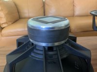
Every day since 1993 I think about that old system and how good it sounded. In time, I learned about the nature of tubes and why that thing did what it did, and still don't know why I have never revisited that. I have fond myself longing for a small portable that sounds that good and something my wife and I can down time with. Or I can sit at sunset on the steps of the sailing club at the beach and enjoy some dub and even play my bass along with

I have the preamp already for plugging the bass into any hi-fi, so the instrument side of this portable is a separate issue already resolved and can apply to this or any other system with a line in

While fitting this to a new bass amp two years ago, I thought about how cool would that have been to plug into the old system that had that glinty golden sheen on the bass of Robbie Shakespeare and Aston Barrett. Things get smaller over time, so why not the old system. After pondering this for the last two years, I think I should dive in head first and build and enjoy this thing instead of just thinking about it

Please take it in the spirit intended and coming from someone fairly uneducated

The thread discussing the LF driver side of things

The thread discussing the FR stereo drivers


I have compiled a good parts bin

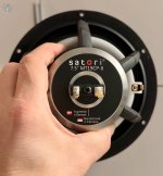
Visaton waterproof FR drivers

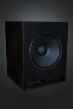
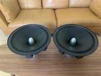
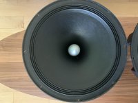
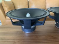
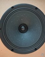
Various 6.5" subs and one JBL BB3 replacement bass driver

Dayton reference alloy PRs, no name PRs

DS18 ZXI-354 FR drivers

7" SBA or Wavecor sub, can't tell

2.75" SBA or Wavecor FRs, can't tell

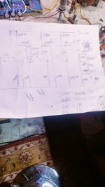
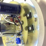
DC24V 2.1 poweramp with DSP TPA3116D2 based with 50w+50w+100w at 4R+4R+2R

Just the DSP

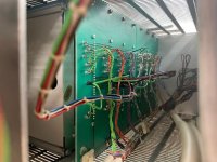
Just the poweramps in separate stereo and mono boards including TPA3116, TPA3118, PAM8403, PAM8610

DC12V to DC24V 15 amp stepper

DC12V to tube power stepper

Various 12v batteries and chargers

Creality 6 Max printer

Desktop CNC router + laser module

Mini industrial table saw

Comprehensive hand and power tools

Calibrated mic

Audio interface

Various software

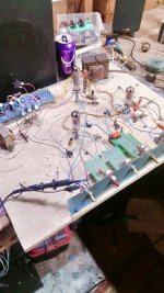
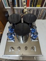
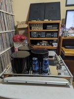
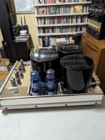
6SN7 tube preamp PCBs and tubes

6SN7 tube headphone amp PCB and tubes

5670 PCBs and tubes

Lots of passives

ECC83 tubes

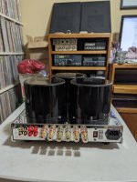
The tools are all for my main interest being bass amps, bass instruments and WIG vessels and the audio components are for trying to achieve the portable through trial and error. During the course of discussion re the FR drivers, it seemed like the starting point of the project, the headphone amp was a bit under equipped, so I am adding an EL34 SET kit into the parts bin including very well specified output transformers as well as Psvane red EL34s. Also adding an analog voltage divider network and analog sub controller to the mix. And a pair of 1.75" JBL long stroke type 15wrms FR drivers

Thinking about adding a very well-made TPA3221 stereo board from NVarcher into the mix too for the sub to run straight from 12v instead of lesser chips already on hand

I feel that I have sufficient mix of parts to trail and error with to end up with a very small version of the HMV unit that is perfect as a low output personal music system for two. Will introduce the model for the max allowed dimensions for the chassis as I work various things out

Troel's Loudspeaker 3 versus Faital 3WC15

I know there will be opinions on better and/or more economical choices. Putting that aside here is my request for opinion set:

Room: Largish 25'x25'
Amplifier(s): Tube SE ~10-15 or Tube PP 15-25W
Doesn't need to play loud, 85db is plenty for me, value midrange vocals and imaging

Loudspeaker 3
  1. Cost (US) $3024
  2. Compression/Horn tweeter
  3. Hypex DSP driven woofer
  4. 92db/2.8v sensitivity
  5. Nice flattish impedance load to amp

Faital 3WC-15
  • Cost (US)$2639
  • Satori Be tweeter
  • 94db sensitivity

Both options using Pro drivers.
So apart from the cost difference each option has interesting features:
LSIII, DSP Hypex woofer driver, horn tweeter
3WC-15, Be tweeter!

If I had to choose between the 2, I am leaning to the 3WC-15. What say others?

  • Locked
For Sale Tango Hirata SE Output Transformers

SOLD

One pair of old Hirata Tango XE-60-3.5s output transformers for sale. This is the earlier generation of Tango, which is the 'original' series, not the later ISO or what not.
Excellent condition, with some mild chipping of paint around the edges which is typical of these transformers due to age.

1695029960620.png


Asking for US$1100, which covers EMS priority shipping to most countries in EU, UK and US. These are 4kg each and the packing will be likely 10+kg for the pair. Trust me, I paid more than this.

Below is a pic of the transformers. And i will be glad to provide more pic in PM if you are interested.
I can accept Paypal Friends /Family only. I have made more than 30 transactions here in this forum.
No bad surprises, all are happy buyers.

Sony MHC-C305 - any use?

Clearing out my parents house, got ahold of their old MHC-C305 sound system. Was hoping to find a use for it by hooking it up to my tv, but seems it only has aux in and mic/phones in ports. Anything I can do with that? I don't really have much use in a radio/cd/cassette, so unless I can find some novel use, probably headed for the dump.

Not my area of expertise, not sure I even posted in the right place, so bear with me!

dual opposing 8 inch

OK for my tiny sub project I am trialing 2 8 inch opposing SB Acoustics subs

8″ SB23MFCL45-4 / Polypropylene - Sbacoustics

They are beautiful drivers.
I am trialing this method of coupling with 4mm threaded rod, 4 mm bolts and hex rod coupler (coupling nut). See pic. Yes I know they are too close - mybad did not measure depth. I might need to increase box size a little.
I tightened it so much the MDF started to bow in the middle.
At the very least I think it needs some sort of extra support, even just a bit of pine in the middle where it bows.
But the main problem is that it needs top and bottom off to be able to install the rods. This is almost impossible to do when you consider finishing (I was going to wood veneer).
Is all this really worth it? Are just normal wood screws really that bad?
It is such a small box I would think the drivers are pretty well coupled anyway.

Attachments

  • PXL_20211030_122433646.PORTRAIT.jpg
    PXL_20211030_122433646.PORTRAIT.jpg
    406.8 KB · Views: 3,845
  • Like
Reactions: lenta and _henry_

PSU for DL-1656 CL m series Compressor/Limiter modules

Hey All,

Hope all is well,

I have 8 Calrec DL-1656 CL m series Compressor/Limiter modules racked.

When I purchased this unit, I brought it knowing that the PSU was not working, after inspecting the circuit board and the PSU I found SO MUCH mouse urine and fecies throughout everything. It had housed a few generations of mice.

So, I cleaned it all, there was slight corosion in places but nothing a cotton bud and some isopropyl couldn't solve.

After the deep clean, it fired up and everything was working perfectly.

Though, after a few months, it sporadically did the issue again, which I am under the assumption that the PSU is overloading the modules, as all the meters go full signal red, pass no signal and after powering it on and off and fiddling with the PSU, it comes good again.

The PSU is a calrec ams ZN2275 0I, I can't find anything online about it.

It has multiple DC outputs +8L, +16L, and -16L.

It has a 5 Pin DC O/P

PINs

1 -16A
2 - CR
3 - +16A
4 - OL
5 - +8L

Just wondering for powering these vintage modules what would be a modern option in order to replace it or if need be, how I'd go about making a custom PSU for them?

Ideally I'm looking to seperate these into 4 racks of 2 modules, does anyone have any recomendations on how to go about doing this project?

Hope someone can help, or point me in a direction that will help.

I have attached some images for reference.

Thanks!

Attachments

  • 426402273_6958170944294856_827628606183593688_n.jpg
    426402273_6958170944294856_827628606183593688_n.jpg
    110 KB · Views: 44
  • 430449643_25126044297009904_4330656112074868295_n.jpg
    430449643_25126044297009904_4330656112074868295_n.jpg
    96.6 KB · Views: 37
  • 430877707_8125356944157583_3741725823503184298_n.jpg
    430877707_8125356944157583_3741725823503184298_n.jpg
    74.4 KB · Views: 39
  • 431009314_25004160412563217_1920049113720173630_n.jpg
    431009314_25004160412563217_1920049113720173630_n.jpg
    156.5 KB · Views: 41

Running EV SX300 Cabs on 600W

Hi guys.

Someone recently gave me a Cerwin Vega CV-2800 Amp. Thing is a beast and I wanted to make sure it was working properly so hooked up my SX300 which is a 300W 8Ohm Speaker with 600W Program and 1200w peak apparently.

The cerwin runs at around 600w Per channel I think I read somewhere at 8 Ohms. Know it is pushing it a bit but wondering how stable I'm sitting if I just wing it and use it as the usual driver. If it is going a bit too far anyone have any idea of some fairly cheap second hand cabs that would go with it, even if I need bass bins to actually get some proper use out of this amp? I've tried looking for Peavey cabs but they actually seem pretty low rating. I was gonna go for Pro-15s and Pro Subs on each channel but I don't even think they'll be supported.

Thanks for the help in advance.

Slight 100 Hz hum with no signal in pure class A amplifier?

Hi all, I'm interested in an Aleph 3 DIY power amplifier, but someone told me to check (and I don't know how because I don't have the possibility to listen to it on my chain) that it doesn't suffer from a slight hum at 100 Hz in the absence of signal , a problem which, again in his opinion, is very common for pure class A amplifiers.

Has anyone who owns or has built the Aleph 3 or other pure class A amplifiers ever actually encountered the problem of slight hum at 100Hz with no signal?
Or could this be a problem that only this person had on one occasion?

Thank you very much

Latest firmware update DENON DVD 3910 and dvd 2900 Enjoy :)

Latest firmware update
(EU -SCART MODEL)

DENON DVD 3910 -Version 8280-5
and
DVD DENON 2900


Enjoy 😀

Attachments

For Sale London UK - Big sale of used 300b tubes - 17 must go

I have a stock of 300b tubes which I no longer use in any amps. They are all used and in most cases well used but they all work and have life in them. So useful to get a 300b amp going or to have something in reserve. Here's the list. Not sure of prices but will look up some prices and post them.

JJ - matched pair testing used but fairly goodish.
EH white ceramic base - quad testing OK, fairly well matched
EH single - works but lower emission
Svetlana - pair, one testing pretty good the other no test results marked on it so anybody's guess
Edicron - single testing OK
Valve Art 4300 - pair, expensive when new, well used but still sound nice
Brown base black anode, no markings - matched pair testing OK
Billington Gold - pair, one stronger than the other, test OK+
Billington Gold - single, works but lower emission

Can be collected from Kensington or posted at cost. PM me for more details or offers. Andy

In room / in place nearfield measurements of a symmetrical speaker system - what are the issues WRT crossover design?

I am still (and will most probably always be) a newbie in loudspeaker measurements. Since I am limited by the climate conditions to be able to measure outside to get rid of the reflections. Therefore this is what I do during the cold period to design crossovers for my (mostly) MEH projects. These are mostly symmetrical in horizontal and vertical plane, the round ones even in more planes at certain frequency bands. I tend to think that the symmetry allows getting better results with the method below than for e.g. a standard two way bookshelf speaker. Maybe it can be also considered a point source as a simplification in certain frequency areas?

I measure the bands and the whole speaker on axis as far as possible without seeing a strong reflection in the measurements. In general, this is always too close for serious measurements - I end up usually somewhere between 30 - 50 cm. I use the traces or live measurement (slightly smoothed for better view) to set the crossovers. The measured FRs even this close are usually in a good agreement with manufacturer datasheets and e.g. Hornresp models. Then I move the mic to the listening position, make a few measurements across the area to get an idea what is the speaker response and what is the influence of the room. Some further EQ may be added carefully to balance the averaged listening spot response.

This gives me usually quite listenable results. I would consider this method to be "better than nothing". Would it make sense to measure "polar response" in nearfield at the place of installation or would such a measurement be totally useless and way off from the proper anechoic measurement? From my experiments, especially if a model (like from ATH/ABEC) is available, I think I can see general trends in the measurements that follow the simulation results. All of that with heavy "brain" filtering and using various gating/smoothing settings on the measured data. For example, the midrange narrowing on my large 9 sided conical horn showed up at the frequencies, where it appears in the model.

My target is to identify areas where EQ is applicable and useful and areas, where EQ is contra productive and set up a DSP crossover. I wonder what are the limitations of such approach and where are the risks of being mislead by wrong assumptions. Any input on this topic is highly welcome.

For Sale Akitika GT-102 Z4 Amplifier (4 ohm version, LM3886)

I built this in 2021 from the Akitika kit. It was built following the very detailed assembly manual to the letter. It's worked flawlessly since turn-on...no issues at all, quiet, no noises/thumps, etc. I used it in my second system, never at excessive volume or with difficult speaker loads (primarily Jeff Bagby Continuum II speakers).

For specs, current pricing, and other info, please see akitika.com

Includes the assembly manual, original box, and packaging.

Asking $220, shipping to USA included. I assume overseas shipping would be prohibitively expensive. Feel free to make an offer.


A1.jpgA2.jpgA3.jpgA4.jpgA5.jpg

The all new NA12

I have just shipped the first pair of NA12's. The data for this system can be seen at my website.

Please note that this system is "passive". There are a lot of very smooth speakers out there these days thanks to DSP, but DSP is not a solution without its limitations. It isn't viable for many people. I know of no other passive crossover speaker that comes anywhere close to the performance of the NA12 (The new NS15 is active). This puts this speaker in a class all its own for those who prefer not to go active.

Speaker cone movement with a single-ended Class A amp

I'm trying to understand how speakers behave when connected to a single ended class A amp circuit. Let's say we've got one output transistor biased to the full amplitude of the input signal. This transistor is connected between 0 and let's say 25 volts. Let's assume that the dc offset is 0 volts. In my understanding, if a positive voltage is connected to a speaker, the cone moves outwards, and with a negative voltage, inwards compared to it's resting position.
What I see here with the class A design, that the speaker will receive a variable voltage but always in the positive range, which makes me think that the cone will be displaced outwards (and vibrate in that range) and never inwards relative to it's resting state. Also because of this, when the signal amplitude declines, it's only the speaker construction (spider and edges) that are going to help the cone to return to a lower position, which means it will be controlled less and might not have the time to move without distortion. I hope someone can confirm this, or contradict it to give me some clarification.

Line switcher with power switching?

Hello I have built a diy enclosure and put a 2 channel amp and smps inside and I would like to have 2 inputs. The main input will be a pair of RCA jacks but I would also like to be able to switch to a Bluetooth module when needed. Is there a way I can switch the inputs and also switch the power on to the Bluetooth module at the same time? The BT is powered by it's own 110v to 5v power supply so can be switched via mains power or 5vdc.

Greeting

Hello!
Glad to join.
I am having an issue with my new Pathos Heritage MKii Integrated Hybrid System that has gone into DC OFFSET mode and cannot be reset. We cooperate with the dealer and the factory. There appears to be no electronic issues in my setup that could have caused this problem.
The dealer suggests that there may be a crossover or driver issue in my Tannoy Kensington headphones. I have access to highly trained local technical support in Chicago. Is it possible to test crossovers and drivers without sending them to Tannoy for service?

For Sale Pair Of AE TD18H+ Drivers

Pair of lightly used Acoustic Elegance 18” drivers. While I would like to keep them I am moving to speaker enclosures with a much smaller footprint. I no longer have the original shipping boxes so pick up in Kitchener, Ontario is really the only option. Price is $800 CND for the pair.

Attachments

  • 0E49D03A-BD9D-4F6A-A79B-875D2B9FA7C0.jpg
    0E49D03A-BD9D-4F6A-A79B-875D2B9FA7C0.jpg
    916.1 KB · Views: 241
  • DED9F5B9-02CA-40B8-98C0-3BB03FD68819.jpg
    DED9F5B9-02CA-40B8-98C0-3BB03FD68819.jpg
    981.3 KB · Views: 255
  • A92C4CBA-35BF-41A5-8B53-E61155E1B24E.jpg
    A92C4CBA-35BF-41A5-8B53-E61155E1B24E.jpg
    971.6 KB · Views: 217
  • 8D8A8867-7B59-4BB2-A08C-B640E3035355.jpg
    8D8A8867-7B59-4BB2-A08C-B640E3035355.jpg
    859.2 KB · Views: 209

Yorkville / L&M drivers: any worth using?

I'm thinking of making a few econowave-style PA cabinets.

The affordable drivers most people have discussed to death are not as easy to get up here.

But there are a few drivers stocked at Long&McQuade (Canada's biggest chain music store) as replacements for their popular "Yorkville" speaker line.

Sadly, it's not as simple as picking out a favourite Yorkville design and buying CD/Horn/Woofer. But the drivers listed here look like they might have some potential for budget Econowave-style designs:
https://www.long-mcquade.com/depart.../Speakers_-_Speakers_Tweeters_Replacement.htm

Of particular interest:
CDs:

B&C DE750 (not currently working on anything nice enough to justify a 2" CD, but it's nice knowing it's available to pick up locally for half the price of anything like this at Solen or Qcomponents)

Celestion CDX1-1410
$52 for 8 Ohm / 40 Watts Program / 104dB
Haven't seen this anywhere else, and I'm not sure if Celestion part numbers mean anything.

CDX1-1070
$43 for 1" exit, petp diaphragm,
8 ohm/ "24W" / 106 dB
Recommended min. crossover: 2200Hz
Seems very similar to the 1445, which is about the same price if you aren't counting shipping cost. Around half the price of the cdx1-1415 with aluminum diaphragm.

Woofers:

Eminence 122669 / Yorkville 7312
$200 on sale
8Ω 900WPGM 3"V.C. neo speaker


Eminence model - 121427C / Yorkville 7288
$120
- 4 Ohm / 100 Watts Program Power
no other specs


EMINENCE 151845B / Yorkville 7336
15" / 8ohm / "225 Watts Program Power / 550 Watts Peak Power"


Anyone know anything about any of these drivers? Any way to decode the part numbers and get more specs?

I'm considering buying a few of the 1" Celestions to replace piezo tweeters in some older PA boxes.

Head Unit Factory Output

Looking for some help understanding the power output of my factory HU. Relatively new to car audio.

2015 4runner, non-JBL, OEM stats claim 140w continuous. I used a plug and play PAC harness to connect a LC7i powered LOC to a 1000w amp; 60 RMS x 4 channels. Rewired all the doors to the new amp with new speaker wires.

The only spot I didn’t re-wire is the tailgate. I want to change out the tailgate speakers, re-wiring the tailgate is something I’m trying to avoid. I know 4runner factory rear door speakers are wired in sequence to the tailgate. My thought is that I could patch the two rear R & L doors with jumpers to put the power all to the tailgate speakers. I’m guessing that would only give me 35 RMS per speaker though using the factory power output.

Two questions:
1) am I correct on assuming I can get 70 RMS from the factory HU if it’s rated to 140 and I’m only using the rear right and left speaker wire outputs, pushing the power to the rear with the jumpers.

2) if I took the front and rear speaker outputs for left and right from the factory HU and connected them to the rear speaker wire (placing jumpers in the rear doors to send the full signal to the tailgate) would the full 140 RMS end up in the tailgate? Would the LOC that’s currently installed take some of that power away? I’m sure I could just put another amp in but trying to save on space here.

I figured the power aspect makes sense but I don’t understand if the signal would get messed up.

I guess my question is if I took all the outputs from the hu blended into two speaker inputs put it into one big speaker, would I get the full output from the HU power wise and can the speaker handle that signal? Would it sound good?

My thought was to do this and install a component system rated for 70 RMS each with some custom fabrications on the back tailgate.

Sorry if any of that is confusing, like I said I’m still learning. Thanks!

AIYIMA A07 Pro

I already have "Aiyima A03" TPA3116D2 based complete amp.I am about to buy TPA3255 Based Aiyima A07 Pro to feel more BASS than A03.

1) How was the Bass performance over Aiyima A03?
2) I am going to connect 5.25" woofer size Philips Bookshelf Speakers for home Audio Listening.
Will I get a noticable different between thses two models A03 vs A07 Pro?
I am a Bass Lover.

For Sale Yaqin MC-13S Integrated Tube Amplifier

Yaqin MC-13S

Minty integrated tube amp. All original tubes with 6CA7-T blue output tubes. About 30 minutes total time on all tubes. All functions are perfect. Amp is quiet and powerful. Here are the specs:

YAQIN MC-13S is considered one of the best class A/B integrated amplifiers in 2021 by review group of amplifier experts in USA and Europe. Of all the components, the transformers stand out most. Both the input and output transformers are very high quality. It starts with the oxygen-free enameled copper used in the windings for the transformers cores. It ends with the use of 35-milimeter Japanese steel sheet employed in the building of the laminated stacks surrounding the core windings.

Additional Characteristics on MC-13S amp :

manual biasing.
4 switchable line input.
Convenient analog VU-meter.
Spec: Output Power: 40W + 40W (8Ω)
Distortion: ≤ 0.9% (28W)
Frequency response: 10Hz-60KHz (± 2dB)
SNR: ≥ 85dB (A weighted)
Load impedance: 8Ω or 4Ω
Power consumption: 240W
Sensitivity: ≤ 0.26 V
Tube: EL34 x 4, 12AX7B x2, 12AU7 x 2
Dimensions: 470(D)315(W) 175(H)mm
Input Power Voltage: AC110V/220V 60Hz/50Hz (110V/120V/230V/240V)
Net Weight: 22 kg

The amp is hooked up to speakers and can be auditioned most any time in my home. You will not be disappointed. Amazon price is $1000.00 My price is $800.00 firm. Would prefer a local buyer as the amp is quite heavy and shipping is going to be high. I am in Pacifica just off Highway 1. This is amp #4 of 6 I am selling.

415-810-7587

PXL_20240305_160340919.jpg

Attachments

  • PXL_20240305_160350281.jpg
    PXL_20240305_160350281.jpg
    368.3 KB · Views: 82
  • PXL_20240305_160358861.jpg
    PXL_20240305_160358861.jpg
    361.8 KB · Views: 69
  • PXL_20240305_160412668.MP.jpg
    PXL_20240305_160412668.MP.jpg
    378.6 KB · Views: 72
  • PXL_20240305_160437437.jpg
    PXL_20240305_160437437.jpg
    348.5 KB · Views: 72

One Audio HT24-4 24" driver

Guys,
i stumbled across this
https://www.oneaudiousa.com/product-page/ht24

24" driver 3kW RMS, 19hz FS and 36mm xmax , sensitivity looks good also
is it feasible to stick it in on a PA cabinet or this is just for HT/CAR duty

COILSINGLE 4Ω
FS19.97Hz
RE3.05
RMS3000-3500w
QMS5.91
QES.44
QTS.40
MMS1037.7g
VAS348.0 l
SD2002 cm^2
LE1.87 mH
SPL90.03 1W/1M
94.22 2.83v/1M
BL30.04
XMAX36mm
(ONE WAY)
OD24.375
ID22.375
DEPTH11.250
  • Like
Reactions: Booger weldz

Faital 12HP1060 midrange quality in Econowave

Does anyone care to speculate whether the FaitalPRO 12HP1060 would be good enough up to 1.2-1.6kHz to pair with a SEOS-12 or similar 1" CD horn in an Econowave style?

IMG_1197.gif


I'm actually building a 3-way at the moment with its ferrite brother, the 12HP1030. This will be crossed at around 325Hz to a PR170M0 midrange (and at 2-2.2kHz to a STH100/HF10AK combo) for better midrange.

However, this single neo unit (12HP1060) basically fell into my lap with no specific plans for it. They're pricey new, so I won't be buying another for now.

So, just for kicks, rather than selling it, I was considering building an outdoor Bluetooth party speaker based around it (think JBL Partybox). In this application, a two-way would simplify things considerably (physical size, amp modules, cost etc.), but I don't want to waste my time building something that's going to sound like crap.

It's obviously not going to sound as good in the midrange as a lower Le and Mms driver, like the 12PR320 or perhaps even the 12FH520 (never mind the TD12M or 12P80Nd that I have elsewhere), but I won't be spending any money on new parts for this (except for a 13S battery pack to power the TPA3255 modules). Punchy, loud bass is more important than midrange anyway in this kind of speaker, and it would have DSP to EQ the response.

I've got a 6PR150 (with a spare STH100/CDX1-1745 combo), or a 4FE35, or a 3Fe22 (with a suitable spare tweeter) that I could use for mid, but again, I would like to avoid 3-way if possible. And with sheet wood costing what it does now and free time being rare, I'd rather just plan it out right from the beginning and not have to build a test box to see for myself, especially on this meant-just-for-fun project.

Stream Spotify with a MOTU Audio Express and a pair of Adam A7X possible?

Hello everyone,
I am new here, so if I am in the wrong place, please move my post elswhere - thanks for that.
I have a pair of Adam AX7 and a MOTU Audio Express. Is there a way to connect may Smartphone or Tablet to the MOTU in order to use the system for listening to the music? I mean a cable or a blutooth dongle or something like that...? https://motu.com/products/motuaudio/audio-express/summary.html
It´s all connected to a tower PC. I just do not want to start the PC every time I want to listen to the music. Maybe the MOTU is just too old for the purpose?
Thanks in advance for the help!

Ukranian Amp Kit

Hi all ,been on here for a few months reading reading and more reading finally took the plunge and this kit arrived yesterday,cheapish off ebay from the Ukraine.Everything there that was stated in kit and now just wondering if any of the highly knowledgeable members might cast an eye over the kit and circuit diagram and offer an opinion. Million thanks in advance

Attachments

  • 20181130_192518-002.jpg
    20181130_192518-002.jpg
    872.8 KB · Views: 1,929
  • 20181130_192434-001.jpg
    20181130_192434-001.jpg
    282.2 KB · Views: 1,984

classdaudio.com

I am in the process of shopping for a new stereo and am interested in building an amp. I came across classdaudio.com in my travels but there really isn't much info about them other than their website and a very limited few threads here with the newest one from 2016 (that I found) so I figured I would bring it up. So I would like to build an amp to save some money since my overall budget is about 1500 and a good amp can easily double this on its own. What is attractive to me with calssdaudio.com is I can get a 500wpc amp for probably less than $500 finished (DIY) built. Anyone have experience with these amps? are they any good?
I have been briefly looking at other options but price is a big factor. Right now the other front runner is a parts express ICEpower amp build. I'm looking to power klipsch 8000F or fluance floorstanding if budget dictates.

Next speaker choice: FHXL, Silbury, Blanda+Grönsaker, then?

Hi,

I've built a pair of Frugel Horn XL with A11MS, a pair of Silbury with MArk Audio A10.3, and I will start building a pair of Blanda+Grönsaker with A7ms (these last will probably be paired with a sub).

I have to say that I really like the FHXL and I'm in love with the Silbury so much that I'm thinking to sell my Klipsch RF82.
So my question is: what do you think I could explore as next build?

Thanks,
Roberto

1979 Oracle Delphi AC belt size

Hi all
Anyone out there know the size of belt for the 1979 Oracle AC ? I know it's a round one but need help with the size . Thx in advance

Attachments

  • 786AF451-04FD-4F29-8D3F-D0207644F611.jpeg
    786AF451-04FD-4F29-8D3F-D0207644F611.jpeg
    403.6 KB · Views: 70
  • 69870714498__EB6E1620-CC50-447B-961B-4F62BCCCB11E.jpeg
    69870714498__EB6E1620-CC50-447B-961B-4F62BCCCB11E.jpeg
    360 KB · Views: 74
  • 69870712584__C2645407-106E-4849-A096-B82473B9EFDA.jpeg
    69870712584__C2645407-106E-4849-A096-B82473B9EFDA.jpeg
    343.8 KB · Views: 68

Tweeter level and high pass filter

Hello,

I'm looking for expertise on tweaking some high pass filter in order to enhance the tweeter's output.


1708577606176.png


1.Would there be beneficial and not detrimental to the phase, crossover point and else, to play with 2ohm resistor? Is it considered to be before the filter? Could a parallel capacitor be beneficial there?
2. In order to preserve the crossover point - does lowering the 2ohm resistor require higher value of 3.5/1.5 capacitor?
3. Could I play with 3.8ohm as well (value change, parallel capacitor)? How does exactly the lamp and the resistor work in tandem.? How detrimental to the sound is this?
4. The 10ohm resistor, parallel to the tweeter, (value change, parallel capacitor)? Any effect on the tweeter's level (or just to smoothen the response, as I read somewhere)or To protect the amplifier (and woofer) in the event of the tweeter being blown (i.e. open-circuit)??
5, Could one bypass the 3.5/1.5 capacitor-the 2ohm resistor-th 10ohm capacitor at once/with one common bypass capacitor all together?
The tweeter is 8ohm

Too many questions, I realize, sorry.
Much appreciated!

BTW, I'm in a process of replacing all capacitors ... The photo shows intermittent state... JB JFX , bypassed with CDE 104K and 940C
1708580867013.jpeg

Electronic Shirts

My neighbor just told me about his new endeavor:
https://www.electronicshirts.com/

Pretty cool, right? If you have suggestions for him, post them here. I asked him to join the site.

He is also a musician and has a good ear. Let's welcome him to this site.

Here is my favorite:
1709694177975.png


I bet @6L6 has a favorite.


Mods: I know my neighbor, obviously, but there is no financial gain for me from this thread.

For Sale FS: (EU) 2x Sica 5" Coaxials 5,5C1,5CP Z002810

FS: (EU) 2x Sica 5" Coaxials 5,5C1,5CP Z002810

I've had these Sica 5" Coaxials in the storage since I bought them new 3 years ago. I'd like to put them up for sale if anyone is interested.

Condition: unused / open box. Taken out ouf their packaging a couple times to take a look, no usage of any kind, stored in their packaging as shipped by TLHP. (Drivers in their plain factory carton boxes plus outer carton box.)

Price: 100 EUR + shipping cost. Payment via normal SEPA bank transfer.

Shipping: shipped from Hungary, the cost of shipping may depend on the destination, I'm not sure. Estimate at least 30 EUR for shipping cost, these days, I think. (Also, the box is not that small.)

Thanks!

Seeking simple bench top multimeter with big, clear display

I want a bench top meter just to have something that lives on my workbench, in the same place, with a nice clear display that I can easily read. I don't really need any more precision or features than my handheld Kline unit. Just ergonomics.

My preference is a used HP or similar unit over something Chinese from Amazon, but I wont shoot myself in the foot just for "legitness"

help ID'ing a melted capacitor? mounted inline? with 240V supply

Thank you all in advance. My Consonance Cyber 880 integrated amplifier wouldn't switch on. This happened a day following 6 hours of uneventful use the evening prior. I switched it off normally. And the next day, it wouldn't power on at all. No noise, no flicker, no sign of life whatsoever.

With some rudimentary diagnostic skills, I eventually uncovered the culprit: it looks like there is a capacitor mounted INLINE inside the AC wire going from the power socket to the power switch. And it has melted/disintegrated beyond recognition.

I only know it's a capacitor because it looks round, and has a sandwitch layout when viewed horizontally. Please see the photos.

My question is, without having access to the wiring diagram for the amp, what would be the likely type/capacitance/voltage value of this capacitor? And what would be its purpose? It's mounted inline after the power socket, before power even reaches the ON switch.

Attachments

  • IMG_3143.JPEG
    IMG_3143.JPEG
    266.9 KB · Views: 159
  • IMG_3142.JPEG
    IMG_3142.JPEG
    279.1 KB · Views: 187
  • IMG_3140.JPEG
    IMG_3140.JPEG
    800.2 KB · Views: 158
  • IMG_3139.JPEG
    IMG_3139.JPEG
    462 KB · Views: 166

A percentage of SPL at the cone vs. port at resonance

Within the domain of BR alignment, is there a formula that highlights just how much SPL emanates from the cone at a decreasing value as the frequency approaches fb & the port "takes over" duties of output?

I have a driver with only three millimeters of Xmax, but the box is tuned at 15.73 hertz...but just how "little" is the cone traversing at that resonant value? Any mathematics to apply?

--------------------------------------------------------------------------------------------------------------------------------------------------Rick...
Projects by fanatics, for fanatics
Get answers and advice for everyone wanting to learn the art of audio.
Join the Community
507,624
Members
7,880,747
Messages

Filter

Forum Statistics

Threads
405,896
Messages
7,880,747
Members
507,624
Latest member
Neilonpoint