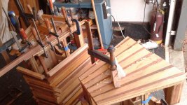
Hi all ,been on here for a few months reading reading and more reading finally took the plunge and this kit arrived yesterday,cheapish off ebay from the Ukraine.Everything there that was stated in kit and now just wondering if any of the highly knowledgeable members might cast an eye over the kit and circuit diagram and offer an opinion. Million thanks in advance
Attachments
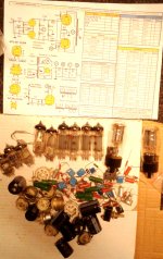
Has everything except trannies , chassis and hookup wire ,has point to point type construction. PP stereo 6P15P(el83)+6N23P = 6N1P(ecc83)+5c4s+6e1p vintage tube amplifier kit | eBay
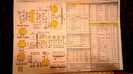
The parts values at the circuit's I/P will expose you high freq. info. loss due to an adverse interaction with the high Miller capacitance of the 6H2Π triode.
The circuit is a differential phase splitter, AKA long tailed pair (LTP), feeding push/pull (PP) O/P tubes. Notice the absence of a NFB loop. Only triode wiring, with R21 & R22 tied to the plates will yield an acceptable damping factor. Speaking of R21 & R22, if you happen to have been shipped 6Π15Π (6p15p) O/P tubes, the value of the resistors needs to be 1 Kohm. The screen grid (g2) in the 6Π15Π is fragile.
Sockets wired for the 6Π15Π will accept the EL84/6Π14Π. Not so the other way around.
It seems you have to supply magnetics and a chassis. If that's the case, purchasing O/P "iron" with adequate magnetic headroom allows for the addition of NFB and the higher power O/P of ultra-linear (UL) or full pentode become feasible.
I'll toot my own horn and suggest you look at "El Cheapo". A lot of what you already have can be adapted to that well proven design. Please notice that "El Cheapo" uses a differential phase splitter too. As drawn, triode mode O/P tubes are shown, but switching to higher power O/P modes is quite feasible, if the "iron" is up to snuff.
Oh yeah, put the (IMO) hokey indicator tube stuff aside.
Attachments
I did some digging. The 5Ц4С is a 5Y3 "equivalent". The 5Ц3С is a 5U4G "equivalent".
I can't comment on the 5Y3 "equivalent". Russian and Chinese 5U4G "equivalents" are garbage, which arc over at power on. The variant to buy in a current production 5U4 is the ElectroHarmonix (EH) 5U4GB.
A 125 mA. capable 5Y3 can't support 4X "12" W. power O/P tubes.
I can't comment on the 5Y3 "equivalent". Russian and Chinese 5U4G "equivalents" are garbage, which arc over at power on. The variant to buy in a current production 5U4 is the ElectroHarmonix (EH) 5U4GB.
A 125 mA. capable 5Y3 can't support 4X "12" W. power O/P tubes.
The parts values at the circuit's I/P will expose you high freq. info. loss due to an adverse interaction with the high Miller capacitance of the 6H2Π triode. <snip>
6e1p, 6h2n 6p14p tubes were supplied
6h2n is really 6H2Π. Transliterate that as 6n2p. For all practical purposes, the triodes are the same as those in a 12AX7/ECC83, but the pinout is like a 6922.
6p14p is really 6Π14Π. It's an "equivalent" of the 6BQ5/EL84.
6e1p is really 6E1Π. It's a "magic eye" indicator type.
A "kenotron" is a rectifier. Is the photo in the initial post actually what was received?
6p14p is really 6Π14Π. It's an "equivalent" of the 6BQ5/EL84.
6e1p is really 6E1Π. It's a "magic eye" indicator type.
A "kenotron" is a rectifier. Is the photo in the initial post actually what was received?
Last edited:
The parts values at the circuit's I/P will expose you high freq. info. loss due to an adverse interaction with the high Miller capacitance of the 6H2Π triode. <snip>
Much better circuit and surely a better amp the "EL Cheapo" I'd build it with the 6 volt output tubes.
6h2n is really 6H2Π. Transliterate that as 6n2p. For all practical purposes, the triodes are the same as those in a 12AX7/ECC83, but the pinout is like a 6922.
6p14p is really 6Π14Π. It's an "equivalent" of the 6BQ5/EL84.
6e1p is really 6E1Π. It's a "magic eye" indicator type.
A "kenotron" is a rectifier.
Just sussed it as you replied thanks
daturat100r,
The "El Cheapo" that was suggested is an alternative amp to build.
But If you decide to build the circuit you started with, your schematic in post # 1, I suggest the following:
R18, 47k Ohms, is the Pseudo current sink for the splitter tube. The top splitter triode is driven by the signal. The top splitter triode plate load R15 is 100k Ohms.
The bottom splitter triode grid is not driven by signal. The bottom splitter triode’s cathode receives its signal from the cathode of the top splitter triode. With the 47k Ohm Pseudo current sink, the bottom splitter triode will have less gain than the top splitter triode. But the bottom splitter triode plate load, R16 is only 82k Ohms, giving it even less gain than the top splitter triode.
Swap the 82k Ohms and 100k Ohm resistors: Make this change: R15 82k Ohms R16 100k Ohms That will make the gain of the two splitter triodes more equal. Then the signal will be more balanced, and the 2nd harmonic distortion, and the 2nd Intermodulation distortion will be reduced.
Of course, you may prefer the sound of 2nd harmonic and 2nd Intermodulation distortions, which is what will happen if you leave the original values of R15 and R16 as they are in the schematic.
Be careful about how many uF you use at C1, especially if you use a tube rectifier. The range given in the schematic is 50 to 270uF. The 5C3S specifies operation with 4uF, and the 5Y3 specifies operation with 10uF. You will not get much hum if you use 4 to 10uF for the first cap, C1; and use 100uF for C2, C3, and C4. Of course you need to keep the transformer HV center tap wire very short to C1 and C2 negative terminals, and then connect a separate wire from C2 negative terminal to the amplifier ‘central ground’ (to localize the current transients to C1 and C2, and isolate that from the rest of the amp). That is good ground loop interference prevention. Do not ground the center tap directly.
The output transformer Turns ratios as listed as 57% Ultra Linear Tap. That will be a little higher damping than traditional 40% UL (57% is closer to Triode mode, and less hard on the screens). In both cases, UL mode or Triode mode, you ought to use the series 100 Ohm resistors, R21 and R22 at the screens (either to the screen taps, or to the plates, respectively).
Triode mode will have about 2 X the damping factor of UL mode.
Depending on your loudspeakers, UL with more power but less damping; or Triode wired mode with less power but higher damping factor may be more to your liking.
R19 and R20 ought to be 1k Ohm, since this amp is either UL or Triode modes, both with plenty of miller capacitance on the output tube grids.
Adding negative feedback can be tricky, will be dependent on the output transformers you use, and how much feedback you use (3dB, 6dB, 10dB). 10 dB of negative feedback will increase the damping factor by about 3 X. Before you add negative feedback, you should listen to UL mode and Triode mode without the negative feedback.
Whatever you decide, have fun building and listening.
Last edited:
You can use the 9 pin sockets you already have, along with the 6Π14Π O/P tubes. The O/P tube RC bias network values change and I'll provide the numbers, shortly.
What sort of speakers do you plan on using? Like it or not, amps and speakers are "joined at the hip" and you need a combination that operate, at least, reasonably well together.
What sort of speakers do you plan on using? Like it or not, amps and speakers are "joined at the hip" and you need a combination that operate, at least, reasonably well together.
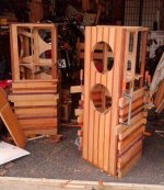
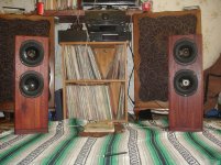
Thanks Eli. Speakers i got are mainly Tannoys of various guises ,am in the process of constructing a pair of three way 10" dual concentrics with dc200 mains driver and some bass drivers from t125's ,a follow on from some cabinets i built for a pair of 636's crushed in the big earthquake.
Its a prelude, or really finishing a project,to constructing some large cabinets,most possibly folded horn, for a pair of 12"monitor golds which should have better sensitivity suitable for valve amps.
Got them earlier this year they were a replacement for my York cabineted 12" MG's i had for nearly 30 years that got regretfully sold after relationship breakdown.They originally came thrown in with a Leak 20/20 with varislope preamp but silly me got talked out of the leaks by a friend who later sold them on(at a great profit).
Really building the amp as along term project ready for when i get a place large enough to house the large tannoys and also as a way of continuing an interest in valve amps ,in the eighties was a partner in setting up a company to produce valve amps for a local constructor/ designer but his paranoia and distrust made it impossible.I left and they limped on ande made a few amps for a few years.Bit of a bummer as had no interest in stealing anything only being keen to help make his product more widely available as well as learning how tube amps work.
This site has been great with its wealth of info and helpful knowledgeable members in stimulating my desire to build me own amp.
Have added some photos of speakers,the larger ones just got their top veneers on today.Dont normally make things that are so "busy" but these are an exercise in using up off cuts from furniture building scrounging etc and sort of inspired by rulers you could by with small inlays of various native timbers.
Sorry rambling on .thanks again Llewelyn
Attachments
I'm anything but expert, when it comes to things Tannoy. A triode wired "El Cheapo" is good for approx. 6 WPC. UL and full pentode modes are good for approx. 12 WPC. So, mid and low 90s sensitivity speakers, respectively, are what you need. Given the NFB loop present, the damping factor is "OK". Remember, no tube amp exhibits the sort of gargantuan damping factor many SS amps do. Keep the impedance curve reasonably flat.
Edcor models CXPP25-7.6K & CXPP25-8K are suitable for a UL mode "El Cheapo". Magnetic headroom is essential, when (like here) a GNFB loop is present. Plenty of metal mass to be found in those models and shipping between New Mexico and New Zealand is going to be very costly. Expect shipping cost to be approx. = to product cost. 
"Crunch" the cost numbers associated with product, shipping, and any import duties imposed. At the end of the day, it may make sense to acquire more expensive "iron" (say James) from a manufacturer physically closer to NZ.
"Crunch" the cost numbers associated with product, shipping, and any import duties imposed. At the end of the day, it may make sense to acquire more expensive "iron" (say James) from a manufacturer physically closer to NZ.
- Home
- Amplifiers
- Tubes / Valves
- Ukranian Amp Kit