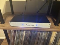
Creek 5350 SE MKI Integrated Amp Restoration
- By frankin4
- Solid State
- 6 Replies
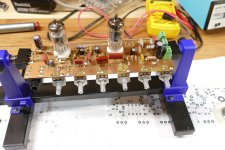
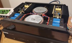
Thought I would post the results of many hours spent getting my 5350SE up and running after it sat idle for months with a channel dropout issue. I suspect there are many of these units sitting in garages and storage bins for similar reasons. After all, these amps are now over 20 years old and who knows how many of them are still working. I bought mine new at the Audio Connection in Seattle in 2002 and it has been in daily use since. The takeaway is that the 5350SE can be brought back to life, with the potential of sounding as good, or better, than ever.
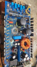
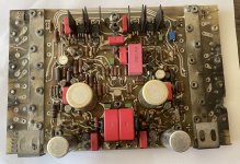
Here’s a list of items I completed on the amp, which I believe is the MK I version, which is a little different from the MK II version and I could not find a service manual or parts list:
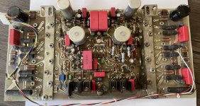
Modifications: Hardwired the pre-amp out/power amp in connection, bypassing the RCA jack and eliminating the U-shaped jumper pins. Replaced the stock rubber feet with solid aluminum feet.
Results: The channel dropout issue is gone and the amp is working properly. It does sound better and by a large margin--perhaps due to the Nichicon KWs, or maybe it was a combination of many things. Music sounds more open, detailed and transparent and bass has more weight and definition. It sounds like a different amp. Even the headphone section sounds better. The improvement is noticeable across all sources and music types. It’s possible the amp may further improve once all the new parts burn in. Channel balance seems improved also—although I have no way to measure it. Anyway, I’m enjoying this amp more than ever and the time and money invested was totally worth it.
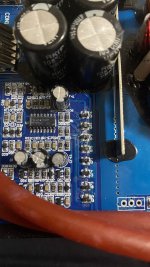
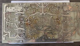
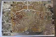
Notes: The most difficult task was removing the Alps input selector, which took about an hour of de-soldering work. You need a very hot iron to get all the old solder out. Good to have a variety of tips for your iron as well. After removal, I cleaned all the contact surfaces with acetone, then 1000 grit sandpiper using a light touch and deoxit, followed by some electrical lube.
I adjusted VR1 and VR101 to achieve a drop across CN2/CN102 of 21.5mV. However, this is the spec for the MKII version and the Destiny. I have no idea if the MKI spec is the same. Any input here would be appreciated.
When trying to isolate the channel dropout issue I swapped Q0/Q12 for Q100/Q112. When I powered the amp on it blew the fuses and one of the Mosfets and produced one of the largest smoke plumes I have ever seen coming from an audio component. I thought the amp was toast--literally.
Some of the failing transistors seemed fine when performing a diode check, but were failing nonetheless. I recommend simply replacing them. This applies to the HUFs, the ZVPs and the BPs. Be careful with substitutes since getting the values right is necessary for a stable running amp.
I’ve never had a problem with the ribbon cables, so maybe I’m lucky. If needed, I will replace them with direct wiring, but doing so could complicate things if I have to remove the PCB in the future. I suspect at least some of the issues others have had with channel dropouts, etc may in fact be due to problems with other components noted herein, rather than the ribbon cables. This is after overhauling four different 5350s and never encountering a ribbon cable issue. It is important to clean the connector pins, however.
It is feasible to remove and open the speaker relays for cleaning (I did it successfully). But the plastic covers are glued on and removing them requires cutting through the glue with an x-acto knife. Then you have to glue them back on. Some degree of mutilation is unavoidable. I recommend replacing them if you have any concerns.
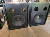
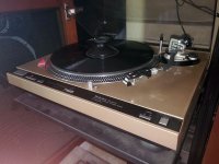
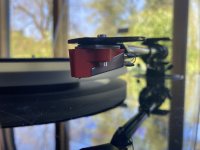
I use the Creek in a mostly analog setup including a Rega RP10 turntable, Sony TC-K777esii cassette deck (restored) and KEF LS50 speakers. I’m probably one of the only ones left on the planet who has a use for two tape loops!
Here’s a list of items I completed on the amp, which I believe is the MK I version, which is a little different from the MK II version and I could not find a service manual or parts list:
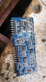
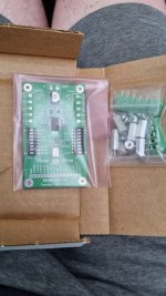
- Removed, disassembled and cleaned the Alps input selector switch, REC-Out switch and speaker selector switches.
- Re-soldered the headphone jack and hot-glued it to the PCB.
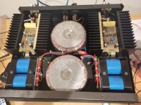
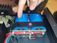
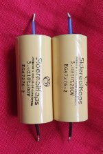
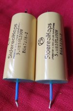
- Replaced all electrolytic capacitors, including the 14 Samwha caps in the power section. For the power section I used Nichicon UKW 50v/2200uf.
- Replaced the main power transistors (HUF 76639P3) with IRL 2910 (x8).
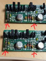
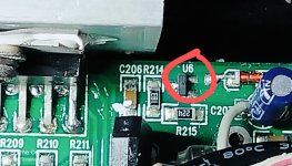
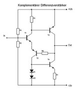
- Replaced Q0, Q12, Q100, Q112 transistors (ZVP 331 0A). **This was the source of the channel dropout issue, combined with failing variable resistor VR101.
- Replaced Q14, Q114 transistors (BP 140-16).
- Replaced almost all other transistors on the main board (BC 556B, BC 546B, BC550B, BC560C). (This was total overkill, but I had time on my hands and the parts were cheap.)
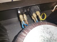
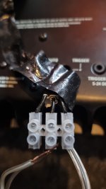
- Replaced speaker relays (TE/Schrack #821024) x2.
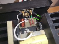
- Replaced power resistors (R28/R44) with 0.33 ohm 7W wirewound flameproof (these are the large ones near the heatsink). The old ones looked a little heat-stressed, although they tested OK.
- Replaced blown fuses with 6.3A T-type (x2).
- Replaced variable resistors (VR1/VR101) with 50-ohm, multi-turn 64Y type (x2).
- Cleaned all speaker and RCA terminals, and the AC input jack.
Modifications: Hardwired the pre-amp out/power amp in connection, bypassing the RCA jack and eliminating the U-shaped jumper pins. Replaced the stock rubber feet with solid aluminum feet.
Results: The channel dropout issue is gone and the amp is working properly. It does sound better and by a large margin--perhaps due to the Nichicon KWs, or maybe it was a combination of many things. Music sounds more open, detailed and transparent and bass has more weight and definition. It sounds like a different amp. Even the headphone section sounds better. The improvement is noticeable across all sources and music types. It’s possible the amp may further improve once all the new parts burn in. Channel balance seems improved also—although I have no way to measure it. Anyway, I’m enjoying this amp more than ever and the time and money invested was totally worth it.
Notes: The most difficult task was removing the Alps input selector, which took about an hour of de-soldering work. You need a very hot iron to get all the old solder out. Good to have a variety of tips for your iron as well. After removal, I cleaned all the contact surfaces with acetone, then 1000 grit sandpiper using a light touch and deoxit, followed by some electrical lube.
I adjusted VR1 and VR101 to achieve a drop across CN2/CN102 of 21.5mV. However, this is the spec for the MKII version and the Destiny. I have no idea if the MKI spec is the same. Any input here would be appreciated.
When trying to isolate the channel dropout issue I swapped Q0/Q12 for Q100/Q112. When I powered the amp on it blew the fuses and one of the Mosfets and produced one of the largest smoke plumes I have ever seen coming from an audio component. I thought the amp was toast--literally.
Some of the failing transistors seemed fine when performing a diode check, but were failing nonetheless. I recommend simply replacing them. This applies to the HUFs, the ZVPs and the BPs. Be careful with substitutes since getting the values right is necessary for a stable running amp.
I’ve never had a problem with the ribbon cables, so maybe I’m lucky. If needed, I will replace them with direct wiring, but doing so could complicate things if I have to remove the PCB in the future. I suspect at least some of the issues others have had with channel dropouts, etc may in fact be due to problems with other components noted herein, rather than the ribbon cables. This is after overhauling four different 5350s and never encountering a ribbon cable issue. It is important to clean the connector pins, however.
It is feasible to remove and open the speaker relays for cleaning (I did it successfully). But the plastic covers are glued on and removing them requires cutting through the glue with an x-acto knife. Then you have to glue them back on. Some degree of mutilation is unavoidable. I recommend replacing them if you have any concerns.
I use the Creek in a mostly analog setup including a Rega RP10 turntable, Sony TC-K777esii cassette deck (restored) and KEF LS50 speakers. I’m probably one of the only ones left on the planet who has a use for two tape loops!