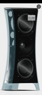
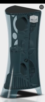
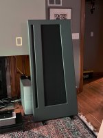
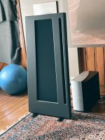
For Sale Accoustat Spectra 1100

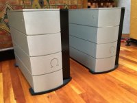
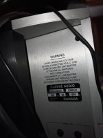
Great condition Accoustat Spectra 1100s. Used to belong to a recording engineer in Australia, made their way here just a year ago. Crossovers upgraded with Clarity Caps and Accoustat’s own documented stability improvements. Power supplies for the electrostatic panels included. Sound great but just don’t work in my space.

Asking $600 $500. Could probably ship them but might be expensive, I would have to come up with packaging. Currently in the Detroit area if you want to hear them.

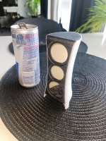
IMG_5114.jpeg


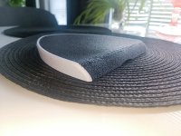
IMG_5115.jpeg


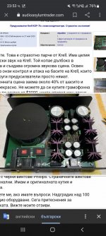
IMG_5105.jpeg

For Sale 4 SEAS 7" woofers/ 2 Peerless 1" tweeters

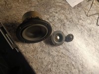
Hi there, I have a couple speaker components figured someone out there could use. These were mounted in a cabinet and work (driven with active crossover biamped for awhile), but I discarded the cabinets and these are available.

There are 4 Seas Prestige H1456-08 ER18RNX Woofers, these are 7" in diameter though the speaker is smaller; these sell for about $120 each.
Selling for $60 each but $40 for the one which I mistakenly dented with my thumb, sorry! (maybe can be an easy fix).


EDIT: woofers sold, tweeters still available

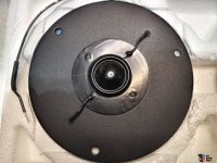
I have 2 Peerless BC25TG15-04 1" Textile Dome Tweeters which sell for about $18 so say sell them for $10 each.

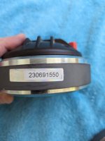
I believe I have the models correct as the links match the physical labels but photographs of the labels on the speaker components are attached for your verification.
I did not buy these, but got them from another user.

Plus shipping or you can pickup in San Diego area.
Mix and match take some or all, its ok w/ me.

Oversized images follow.


04 tweeter.jpg


05 pair tweeters.jpg


I don't deal with speaker parts normally (I build amps) so let me know if these prices are wacky.

Adding bluetooth to a Cambridge AM10

Hi. Clueless n00b here! First look into DIY audiophilia.

I'm giving my son my Rega P1 and Cambridge Audio Topaz AM10 for uni. He's going to source some used bookshelf speakers off Ebay. I'm going to try a self-build to power my old Acoustic Energy floorstanders. That's a project for another day.

He wants to be able to stream via bluetooth to the amp too. I've bought a board for £8 off aliexpress, that uses the Qualcomm QCC5125 chipset and an ESS dac chip, with quite presentable results. At the moment, it's powered by a phone charger with output wires taped to a pair of phono inputs on the back.

There is a 3.5mm auxillary front-mounted input, which he plans to use for laptop input. The bluetooth board has an analogue audio input which, if bluetooth is not connected is passed through to the output. So the plan to make matters more elegant is to put the bluetooth board inside the chassis with the external antenna it shipped with mounted on the back of the amp. Wire the 3.5mm jack to the input of the bluetooth board then the output of said board back to where the 3.5mm output originally connected to the internal circuitry of the amp. Thus if bluetooth disconnected, the 3.5mm input just goes out to the new board and back again but if bluetooth connected, this input is overridden and the bluetooth audio plays.

The quandry is how to power the bluetooth board. I could drill a hole in the back of the chassis and run a usb cable in but it's a bit rubbish - you'd need to either leave it powered full-time or remember to power it up when you use the amp. Now, the amp has an LED array/display which lights up when you bring the amp out of standby. This appears to have a 5V supply. I am not an electronic engineer! Is there any danger in splicing wires from the +5V and GND wires from the LED display to the bluetooth board? That way, when the amp is brought out of standby, the bluetooth powers up and he'll have an amp that does everything he needs from one box.

Thoughts please!

Group Buy for Toshiba Q-Set for the F5Pi

First of all my apologies for the delay.
Partly because I was travelling for 3 weeks, and then needed another week to get everything back to normal.
Partly also I want to wait till the GB for US version to complete first, to avoid running both in parallel.

As mentioned earlier, we can offer a maximum of 21 sets of curve tracer matched Toshiba transistors for the F5Pi.
They include :

a quad of 2SK170BL/2SJ74BL, NNPP matched for Idss, NN-PP matched for Yfs at Idss
a quad of 2SK2013/2SJ313, NNPP matched for Vgs and Yfs at 100mA at 55°C
a quad of 2SK3497/2SJ618, NNPP matched for Vgsand NN-PP matched for Yfs at 1.2A at 55°C

The JFETs and power MOSFETs have different Yfs by design, hence no NNPP is possible for Yfs.
These are the same specifications as used in our prototype.

We shall leave the GB open for 3 weeks, and then we shall call for payment and start shipping.
We do not expect all 21 sets to be fully subscribed, but then we also did not the US version to either.
The Q-sets have already been packed and ready to go any time.

Then of course you want to know how much is the damage.
Currently, the only serious offers on eBay for 2SK3497/2SJ618 are asking for 120USD per quad, unmatched, +10% shipment.
NNPP quads of 2SK2013/2SJ313 Vgs matched are 75USD a set.
And 2SK170BL/2SJ74BL Idss matched are 45USD a set.

As we offer tighter matching tolerances at working temperature, plus Yfs match, we think 2500 HKD including postage is a fair price.
This will include e-Express shipment plus fully insurance to countries where service is available.
Else they will be shipped by registered air mail.
As always we ship FOB, but will keep all shipping invoice in case of loss claims.

Because some of you have already ordered BoM from Fran, we shall deduct 100HKD from the above.
i.e. the Q-Set alone will cost 2400HKD, shipped from Hong Kong, all inclusive.
If you have not ordered BoM, please do so at Fran's GB, for the sake of tidy version management in case of need for revisions.


Many thanks for your support and interest,
Patrick


PS :
1. A complete set of the PCBs used in our prototype, including volume control, will be offered in a separate GB.
2. As Fran also knows, all our "profit" never go to our pocket, but only into future projects, with at least 5 already lined up for 2024.

What can I make from these components?

Hi. I bought an "unknown amplifier". It has Mic and P.U. as sources. Clearly a mono amplifier, somewhat akin to a public address amplifier. Might have been used by a DJ in the past.

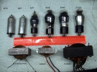
I attach a picture of the principle components. The only thing I can think of to do with these components is to make guitar amplifier. Or a regular "hi-fi" amplifier where left & right audio channels would be mixed together in the mono output. The output I think would be quite low, Maybe 10 Watts? The two 6V6G tubes are wired in push-pull, or class B. It appears it's made in France. There were two outputs, (wired in parallel,) marked H P.

I'm not entirely certain the valve marked "6J7" in the photo is the correct marking for the valve. It's not a triode valve, probably a pentode.

I need to fix that audio output transformer, but will create a new thread for that. Please comment if you have anything to say. Thank you.

Attachments

  • Unknown audio amp (1).JPG
    Unknown audio amp (1).JPG
    577.9 KB · Views: 132

Quick question about TV damper diode specs

I'm a little bit confused about TV damper diode current specs. Specifically the maximum current and the peak current.
I'm using EY88 diodes in my power supply in a full wave center tapped configuration. My amp consumes 250 mA.
EY88 max current is 220 mA. Peak current is 550 mA.
My amp has been working flawless for months so I'm not that worried, but still, they are above their max apparently.
I understand that what they were intended for is not the way I use them,. but I'm having trouble giving it a place. Why the difference between maximum and peak current? Is 220 mA what it can take continuously (non stop) and 'peak' for occasional short bursts? Which one is closer to rectifying 50 Hz AC?
Any insights would be appreciated, thanks.

Zen -> Cen -> Sen, evolution of a minimalistic IV Converter

One day on the return journey of a business trip, I had an idea of using a JFET version of Leach’s MC headamp as IV converter for current-out DACs. A month later, various circuits were simulated, bread-boarded and measured, and prototypes with proper PCBs were built and tested. We also did listening tests using our own SD player and AD1865 DAC, and were very pleased with the results.

I took them to Jan Didden one evening for some distortion measurements with his Audio Precision System One. He was so impressed that he wanted to include the article about this development in his Linear Audio Magazine, Volume 2, due out at the beginning of September. In support for Jan’s enthusiasm in running the magazine, I duly obliged.

So you can now read the entire story in detail in Linear Audio. To facilitate experimentation of the circuits, we shall make available an evaluation kit, but only if there is sufficient interest (minimum 60 sets).

Jan has generously agreed to me publishing the schematics, bill of material, PCB layouts, and some measurement results here. So in theory you can build the circuit without reading the article. But I strongly suggest you do, not only to understand how it works, but also how to adapt it in the many possible configurations to your need.


Patrick

Effect of Stylus friction on LP

I started this thread because there's lot of controversy of what's actually happening between Stylus an Vinyl while playing a record.
The reason not to see it as just a simple gliding process is because the friction coefficient between Diamond and Steel with 0.1 is roughly three lower as the 0.3 between Diamond and Vinyl.
This 0.3 seems rather accurate as measured by Pardee, see attachment 2

Despite the much lower friction, a stainless steel LP proves to be almost unplayable and shows large abrasion damage to Diamond and LP after playing it just once.
So, this posting is a search for the reason, why a vinyl LP can be played over and over with only very minor wear to both LP and Stylus.

I would like to start with a copy of an email I received from Dagfinn with definitions as a reaction to our earlier discussions, it's helpful as a starter for the discussion. In this discussion reference is made to Bastiaans, see attachment 1.

/////////////////////////////////////////////////////////////////////////////////////////////////////////////////////////////////////////////////////////////

Bastiaans states in the intro: "At high bearing loads complete plastic flow sets in and the needle leaves a permanent indentation track, while at lower loads the elastic deformation is predominant."

  • Understanding "elastic" as defined by https://www.britannica.com/science/elasticity-physics "elasticity, ability of a deformed material body to return to its original shape and size when the forces causing the deformation are removed."
  • Plastic: "plasticity, ability of certain solids to flow or to change shape permanently when subjected to stresses of intermediate magnitude between those producing temporary deformation, or elastic behavior, and those causing failure of the material, or rupture (see yield point)." https://www.britannica.com/science/plasticity
  • Yield point: "yield point, in mechanical engineering, load at which a solid material that is being stretched begins to flow, or change shape permanently, divided by its original cross-sectional area; or the amount of stress in a solid at the onset of permanent deformation. The yield point, alternatively called the elastic limit, marks the end of elastic behavior and the beginning of plastic behaviour." https://www.britannica.com/science/yield-point
  • Deformation and flow: "deformation and flow, in physics, alteration in shape or size of a body under the influence of mechanical forces. Flow is a change in deformation that continues as long as the force is applied." https://www.britannica.com/science/deformation-mechanics
So, vinyl is elastic and bounces back until a yield point is reached; where plastic flow sets in, permanently deforming the vinyl. I don't think melting point is at play. Rather the question is when does vinyl reach the elastic yield point, where it starts to permanently deform ever so slightly due to stylus force and maybe increased temperature? Leave a record in the sun for a while, it won't melt, but permanently deform for sure.

From Bastiaans: An important detail is that the "slight permanent indentation" seen is made using a spherical stylus with a relatively small contact patch, which applies a much more concentrated force than a line contact stylus like Shibata.

The Shibata was developed just because of the wear observed from elliptical styli when developing CD4, in the years just before 1970. In order for an elliptical to track CD4 45khz, exceedingly high VTF was needed, and wear was too high. Shibata improved that a lot, and today several line contacts have equal or even greater contact patch compared to Shibata.
A MicroLine tracking at 2g, for instance. It's contact patch is much larger, as is the radius of the same patch. (Or even at lower VTF, like T4P standard 1,25g.)
///////////////////////////////////////////////////////////////////////////////////////////////////////////////////////////////////////////////////////////////////////////////////////////////////////

Conclusions

The main question at the start of this thread was: why is a steel LP unplayable, causing great damage to LP and tip after just one time playing and why is Vinyl so much better suited as information carrier .

  • I was hoping on a Skating on Ice similarity, where a thin layer of very low friction “slurry” is formed under pressure. However no further evidence is found to support this for a Diamond tip riding on Vinyl.
  • That plastic melts into a fluid under the tip pressure as propagated by some can be completely rejected.
  • Temp rise of the Vinyl groove because of static stylus force and dynamic friction while playing, will not exceed at the most a few degrees, where the friction component is dominant.
    See below “Temp rise from pressure versus rotational friction”.
  • As long as the stylus is faithfully following the track, static pressure on the groove wall is far greater than the additional dynamic pressure while playing despite huge acceleration.
    See below “Static versus Dynamic pressure”.
  • However, when the stylus is temporarily mis-tracking because of very high modulation because of a stylus force that´s too low or wrong anti skating setting, the stylus will be catapulted into the air and when landing back into the groove it may exceed the yield point, leading to permanent deformation.
    See below: “Mis-tracking”.
  • The only plausible explanation for the difference between Steel and PVC as the LP’s information carrier may be because of their Young’s modulus that’s 100 times larger for steel as for Vinyl.
    Compare both materials for wheels under a car.
    Rubber (read Vinyl) with a high elasticity, rides comfortably. Even low profile tires (read Shellac) are still doing an acceptable job, but changing the tires for steel versions will make the care undrivable, with great damage to the steel tires and the road.
    Downside however is, the more flexible the groove wand, the more the deviation from the envisaged groove track, leading to distortion of the audio signal.
    LAST with their preservative to treat the Vinyl just once, claims extended LP life and IMD figures that may be 10dB lower as without, so does it increase the PVC’s Young´s modulus in combination with a more slippery surface?
    Unfortunately I couldn’t find any tests confirming this.
    But as Pardee has measured, the coefficient of friction can indeed be lowered from 0.3 to almost 0.1 with certain preservatives.
    That’s why I have planned to do the IMD and the Pardee friction test in the time to come.


Permanent deformation

Bastiaans applied a very thin soap film to the groove wall, played a record and inspected after playing the wideness of the trace where because of permanent deformation caused by plastic flow the soap was scraped from the groove wall. With a 17.8u and a 11u round tip, above 2gram stylus force, theory and practice where perfectly in line and confirming the indentation., a formidable mathematic prestation.
Below 2 gram stylus force the deformation slope did suddenly deviate from the prediction maybe because of a surfboard effect according to a suggestion from Walton.
With a 17.8u diamond and 2 g force, stylus pressure becomes 4.8e4 psi, where the yield point of vinyl is 1.4e4 psi, so permanent deformation because of entering the plastic state was to be expected.

With a Shibata or Line Contact Stylus, the pressure or force per square inch becomes much smaller, so most likely with these more modern styli, deformation will be much less with 2 gram force.

1694805425797.png


Mis-tracking

The earlier mentioned effect of mis-tracking, or stylus loosing contact with the groove, will be followed by a hard landing back into the groove.
According to F=m*a, the pressure on the vinyl because of the huge acceleration force may exceed the vinyl’s yield point, resulting in permanent deformation.

An excellent example is given in the photographic image below, taken with a Keyence VHX-7000 microscope, from a brand new LP played after multiple playings with a Grado Cart with a tracking force of 1.5gram. Stylus shape unknown, but looking at the indent’s shape, most likely a round tip.
The LP in question was Pink Floyd's Time from Dark Side of the Moon

1694805460179.png

Permanent damage caused by mistracking


Temp rise from pressure versus rotational friction .

Some documents are mentioning that, under the stylus pressure, the Vinyl is melting, almost giving the impression that the free air melting point is reached.
Between 70C and 80C, PVC starts evaporate chlorine and at 215C PVC really melts.
Using P*V=R*T should help to prove this huge temp rise. However the Boyle / Gay-Lussac law only applies to gasses and is not of any use in this case.

That under enough pressure the elastic state above the Yield point may turn into its plastic state is true, but this not the same as melting. Compare it to overstretching material that doesn’t turn back into its original position. In this case the tip force of a few gram makes the PVC hardly rises in temp as can be measured on the Diamond tip having a very high heat conductivity, however attempt to measure a temp rise in static position showed results smaller as the equipment’s accuracy.

With a coefficient of friction of 0.3 and a stylus weight set at 2gram or 20mN, force to drag the stylus through the groove is 6mN.
When moving on the LP’s outer groove, speed is 0.55m/sec, resulting in 3.3mWatt turned into heat.
The only halfway reliable tip temp measurement I know of is from van den Hull with 60C, so a 35Kelvin temp rise above room temp.
But others like George came with much lower measured results.
Higher than 60C seems very unlikely because playing at 78rpm would increase the 3.3mW into 7.8mW and accordingly resulting in a ca 107C tip temp.
This could permanently damage the vinyl (or shellac) which does not happen, so even 60C may be questionable.

But still assuming the 60C tip temp as being correct, a large 3u*10u contact surface to conduct as much heat away from the tip and a penetration depth of 10u into the vinyl and using a heat transfer ratio k for Vinyl of 0.15, results according to k*(contact area)/(penetration depth) into 0.45uW/K.
The heat energy transferred from a +35Kelvin heated tip to the Vinyl becomes 35*0.45=16uWatt.

Again back to the outer track that moves with 55cm/sec.
In one second the PVC volume being heated is in 55cm*10u line contact*10u penetration depth is 5.5e-5 cm3 and with a specific PVC weight of 1.4 gives 77.7e-5 gram PVC material.
Specific heat for PVC is 0,9J/(gram*Kelvin)
Applying the earlier calculated 16uWatt for one second equates to 16uJ, and with the 7.7e-5 gram this results in a temp rise for the groove of 0.23Kelvin.
Play a bit with penetration dept and line contact area, and it becomes clear that because of friction temp rise of the groove wall will in all cases stay below a few Kelvin.


Static versus Dynamic pressure

Bastiaans measured on a straight groove, where in real life the tip undergoes huge acceleration forces.
A 0.5mg stylus, being exposed to 2.000m/s^2 will see a force of 1 mN according to F=m*a, to be combined in some way with 19.6 mN (or 2gram) tracking force, so that's seemingly not playing a big role. Static pressure seems to be dominating as long as the stylus faithfully follows the groove.


Hans

Attachments

Should I halve “Re”?

I’m designing three-way “dual woofers” speakers format. The woofers used are 8 Ohms nominal resistance. I wonder when designing the crossovers in the software, should I use “two 8 Ohms drivers in parallel” or “a single 4 Ohms driver”?

In theory, they should have difference on SPL of the woofers. That is one will produce extra 6dB at woofers’ operating range, while the other will not. But, what else?

Getting the best out of Allo.com's new Katana DAC...

Allo's new Katana DAC joins other recent offerings such as the ApplePi DAC, Markw4's experiments with other ES9038Q2M boards, Ian's prototype ESS-based DACs, Abraxalito's LingDAC, and others in raising the bar for RPi I2S DAC Hats. I was one of the lucky ones who given the opportunity to hear this DAC as Allo refined it into the well-performing product it is today. I listened to the Katana with high-performing power supplies and was rewarded with sound in many ways as good as any I've had at home.

I posted some of my experiences with power options for the Katana, isolator, and RPi over in Allo's main vendor thread here:

New FIFO buffer for RPI/SBCs

I'm creating this thread to discuss getting the best from the Katana, including, but not exclusively power options. I'm hopeful Soundcheck and others will post some of their op system, player software, driver, and hardware tweaks. And I'm sure there are other areas to explore.

Based on Allo's recommendations AND my experience, you'll get the best performance from your Katana with 4 power supplies:

- 5V/1A-2A RPi / Isolator input (>1.2A or may not boot consistently in my experience)

- 5V/200mA Isolator output / DAC board (measured 100mA DAC board only)

- 5V/20mA Microprocessor board (with +-15V DC-DC converter disabled, 1A with them active)

- +-15V/100mA-150mA / rail Opamp board

I am focusing on variations on this configuration in this thread.

I outlined the components and configuration of the best supply setup I found in my testing so far in post #4 below. (NOTE that the cost I listed for the RPi and Katana package combined is about $120USD high, due to misunderstanding how Allo listed the components). I will focus on additional options for this configuration in this thread and where I can make comparisons, how they compare to what has been my best so far.

Below are some sources for appropriate completed supplies and kits, and components that will work for the various Katana rails. This is not an exhaustive list, feel free to post or PM me with additional sources and I'll add them here. AND as you have tried them with your Katana, please post your results:

Mamboberry HD DAC+ - Collybia.com - 5V Mambo power supply

Twisted Pear Audio - 5V Placid HD or Centaur, +-15V Placid HD Bipolar or LCBPS, and appropriate transformers

www.ldovr.com - various DC input board sets for 5V & +-15V and DXP complete supplies for 5V

MPAudio | Home of the HPULN | LT3045 based Power Supplies - various DC and AC input board sets for 5V & +-15V and appropriate transformers

www.diyinhk.com - various DC and AC input board sets for 5V & +-15V and appropriate transformers

www.kandkaudio.com - 5V/12watt AC input low voltage power supply kit is what I use for RPi / Isolator input power and would also work well for the other 5V supplies

www.glassware.stores.yahoo.net - several AC and DC input power supply kits for 5V & +-15V.

www.amb.org - various DC and AC input regulator board sets and some parts... YOU will need to source transformers and the remaining parts

www.sparkoslabs.com - high-quality discrete regulators for building your own 5V & +-15V supplies

www.belleson.com - high-quality discrete regulators for building your own 5V & +-15V supplies & supply build articles

www.newclassd.com - high-quality discrete regulators for building your own 5V & +-15V supplies

www.diyaudio.com/forums/group-buys/322596-gb-salas-sslv1-3-ultra-bib.html - Salas shunt regulator boards and partial kits for 5V & +-15V... YOU will need to source transformers and the remaining parts... there are other products and group buys in the DIYAudio Vendor forums, please feel free to recommend additional products

www.jameco.com - low cost 5V/1A & 12V/1A linear regulated wall adapters that can be modified into credible low-cost alternative supplies for the Katana

One supply that has exhibited issues with the Katana is this one:

https://www.audiophonics.fr/fr/alim...re-regulee-op-tl072-mje15034-28v-p-12753.html

Based on several reports, these may require additional C on the output and possible connection to the load after they have fully powered up to function well on the Katana +-15V rails.

My tips on separating the Katana boards without breaking the inter-board connector pins in post 2574 of the main Allo.com thread

AND here's the current state of my Katana:

- 2nd release Katana with firmware fixing the original issue, but not the latest firmware

- Isolator 1.2

- Developmental upgrades that were incorporated in lastest production including additional power lines filtering, updated I/V filtering, and SQ mod (but using an alternative pre-I/V filter not chosen for production)

- +-15V supply (post #28)

- Direct 5V bypassing included connectors on DAC and Microprocessor boards (post #217)

- +-15V on-board LDO bypassing & revised filter Cs (posts #299, #301, #311, #316)

- DAC and Isolator board jumpers bypassed with soldered jumpers

Greg in Mississippi

Simple DSD SRC for BeagleBone

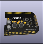
I propose for discussion a new project SRC on dual AK4137. The first AK4137 upsumpling PCM to 176/192, the second converts to DSD256.
Dual AK4137 allows you to convert to DSD256 without significant loss in quality.
This cape cannot claim to be HQPlayer's conversion quality, but it can compete with Roon software conversion.
The firmware for the BeagleBone will be published later. After I debug her work.

The project is open. I will be happy to hear your wishes for further development.

P.S.
I updated the DSD'it versions. A complete set of documentation always available at http:://puredsd.ru

Attachments

  • ak4137.pdf
    ak4137.pdf
    79.1 KB · Views: 777
  • dsd'it.png
    dsd'it.png
    515.1 KB · Views: 2,548
  • Like
Reactions: iperv

OPA1656 distortion when using at low voltage.

In short, OPA1656 shows very high THD level when voltage below +-9 Volts.

Experimenting with Sallen-Key Filter, I observed unusually high distortion level with OPA1656, reported in this thread :
https://www.diyaudio.com/community/...range-oscillator.205304/page-490#post-7012005
and more here
https://www.diyaudio.com/community/...range-oscillator.205304/page-491#post-7014043

To simplify test set-up I change circuits to :
THD measurements.png

You don't have to use SA, distortion level obvious on oscilloscope screen.
I repeated measurements a few times, using sets of resistors:
1). 10 Ohm - 10 kOhm, 2). 100 Ohm - 100 kOhm, 3). 1 kOhm - 1 MOhm 4). 10 kOhm - 10 MOhm

Set 1 produces no visual deviation at all.

Sets 2-4 shows almost the same:
1k3v.png
1k6v.png
1k9v.png


Disregard offset issue with +-3V power, see abnormality with +-6V. Blue line - Input 1Vp-p, yellow - output.

For Sale NOS KEF T27, SP1032 tweeters for LS3/5a clones or replacement of damaged one

I have 5 of those tweeters , one without protective mesh , three with protective mesh and one still sealed in factory box. All came form closed down speaker service shop.
$100 a piece.

Attachments

  • Kef tweeter.jpg
    Kef tweeter.jpg
    120 KB · Views: 137
  • Kef tweeter 2.jpg
    Kef tweeter 2.jpg
    142.8 KB · Views: 135
  • kef tweeter 1.jpg
    kef tweeter 1.jpg
    86.8 KB · Views: 124

Hum (new question)

I put together an amp a few months ago, and noticed there was a bit of hum through the speakers in the midrange when powered on. Other amps I've built before had no hum, so I assumed the large amount of bias current in this amp was the culprit. Not sure why I thought this in retrospect. Recently, I hooked up another amp with much lower bias and there it was again, the same hum. This time, I had to figure the issue was the power supply, since it was the common component in both of the hum producing amps. I used a spectro on my phone to find the major spike was at 180Hz, another lower spike at 240Hz, and some more multiples of 60Hz trailing off from there. Sounds like classic ground loop (I think?). I'm just not sure what's producing it.

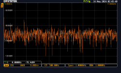
I connected just the power supply to mains and hooked it up to a scope. No chassis, just had the boards on my bench. When Earth ground is connected to GND out the smoothed side of the capacitor bank, I can see the 180Hz spike on my scope AC coupled with the probe on +, shield on GND:

DS0002.PNG

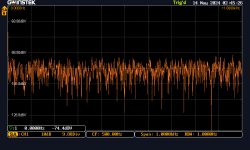
When the mains ground is disconnected, no spike:

DS0001.PNG

This behavior persists regardless of whether or not live and neutral are connected.

Just to sanity check myself, GND should be connected to Earth ground so that fault current has a safe path, right?

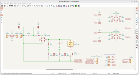
Here's the soft start and rectifier board schematic:

Screenshot from 2024-05-13 13-44-59.png

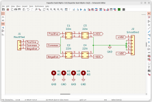
It's connected to the capacitor bank via the Positive-Common-Negative terminals:

Screenshot from 2024-05-13 13-56-49.png

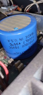
The capacitors are Mlytic 4-poles. H1-4 are case screws. I connected one of the screws to Earth ground via an alligator clip for my test.

Would really appreciate any help tracking down the source of the hum.

Here's a Mystery: Marshall Origin 50 Stuck in Low Power

Customer comes in with a Marshall Origin 50 that once played, but then one day the sound just "turned to sh*t" as he put it.

I found out that the amplifier was stuck in low power mode (3 power settings via toggle, controls screen grid voltages of power tubes).

I discover that the power is being limited by the circuitry related to TR11/12. If I remove TR11, the amplifier can be set to all three power levels and works normally.

If you look at the 4R 8R 16R jacks (speaker outs), you see there are three diodes. Their job is to pull base of TR11 low and enable full power operation.

The way it's supposed to work is that when the barrel of 1/4" plug is inserted to any jack, the cathode of one of the 1N4148 diodes gets pulled to ground.

However, that is not happening. It's the opposite. When the plug is inserted, the contacts open up, preventing the diodes from being grounded. The other side (terminal NR) seems to be the one that SHOULD be connected to the diode, but it's floating on this schematic.

I tested all three jacks with a plug into it and they all behave the same. Plug inserted, D201/202/203 lose ground. Yet the amp supposedly worked, according to customer.

I have removed TR11 to test my hunch and the amp can be set to all three power levels now. The way this is wired, I don't see how this ever could have worked.

1707092998254.png

DIY ProLogic II

I am not using a receiver for my home theater. My source is a personal computer and it's output goes to a four channel amp. (Not a receiver.)

If any of you are in a similar boat, and you're interested in doing some Dolby ProLogic II type stuff, here's how.

OK, first off, what is ProLogic II?

The short answer is that ProLogic II is a decoding scheme that takes a stereo signal and turns it into six channels. There were some later iterations that can turn it into eight channels and there's really nothing stopping you from turning it into a hundred channels. The only limit is your amp channels and your sound card channels.

1204fos.1.jpg

Stereophile did an excellent interview with Jim Fosgate (of Rockford Fosgate) about his ProLogic II decoder and it's history : https://www.stereophile.com/interviews/1204fosgate/

attachment.php


ProLogic II uses a matrix to do the decoding. The pic above is that matrix. Dolby has published their spec and this is it. Let me translate the pic into English:

1) We take the left channel of the source and feed it to the left channel of the output
2) We take the right channel of the source and feed it to the right channel of the output
3) We take .707% of the left channel and .707% of the right channel, combine them, and feed them to the center channel of the output. (Note that this means the center channel is louder than both the left and the right channels.)
4) We take .87% of the left channel, invert it, and combine it with .49% of the right channel, and feed that to the left surround channel
5) We take .87% of the right channel, invert it, and combine it with .49% of the left channel, and feed that to the right surround channel

  • Poll Poll
For Sale Radian 5210-8ohm coax pair 10"

what is the Fr?

  • 67hz

    Votes: 0 0.0%
  • 68Hz

    Votes: 0 0.0%

I bought this pair of Radians from Al at US Speaker thinking I was going to do a coax build, but moved on to other projects so I'm moving them on. They're in mint condition, and the only use they've seen is testing FR and TS parameters. I altered them slightly from stock by removing the mesh that concealed the horn, I think they look much better that way!
Retail is $400 a piece, plus shipping, but I'd like to get $600 for the pair. These are sweet drivers and I'd hold onto them but I need to raise funds to feed my habit 🙂
Here's a link to the specs on the US Speaker page: https://usspeaker.com/radian 5210-1.htm

Photos below, thanks!
IMG_6359.jpeg
IMG_6357.jpeg
IMG_6358.jpeg
IMG_6360.jpeg
IMG_6361.jpeg

Digikey poor customer service

Anyone else had issues with Digikey when it comes to a problem with an order?

Over 10 days ago I received 6 On-semi transistors, 4 of them had bent pins ( even though they were in their original packaging) , that’s not such a big deal but when testing the transistors they’re all out of spec with hfe readings of over 83 ( they should be between 15 to 60 )
I contacted Digikey’s customer service who asked for photos of the damage and the test results ( more photos) , that was 8 days ago , I contacted them again 2 days ago and they claim to have not heard from me since asking for the photos ( I then sent them a screenshot of the sent email) again I’ve heard nothing back .

Up until this I thought their service was excellent and last night I checked out some reviews online and I was quite surprised at the amount of negative reviews.

Looks like Mouser will be getting any future orders from me as they have always been excellent, even when I had an issue.

6F6G PP Amplifier design

Hello!
I am trying to calculate component values for my next amplifier project which schematic I have attached below. The power stage is ok for the moment, I know I can run a B+ of 350Vdc for triode connected 6F6G from the valve datasheet. I would like to use 6N7GT as a LTP phase splitter, as it is accessible to get at a decent cost. I know there is a russian equivalent valve (6N7S) but I have already built some amplifiers based on russian valves and I want this one to be different. The input stage I am thinking that could be one section of 6SL7 triode.

Anyway, the problem I get into, is that I can't find a good loadline for the 6N7GT phase inverter. I am sure that I am missing something as I am not an expert in designing valve schematics. Also, it would be a good thing if somehow would be possible to elevate the cathode of the 6N7GT to around the value of the Ua of the input stage, so I ca have them DC coupled.

Can you please have a look at the schematic and make any suggestions?

Thanks in advance for any bit of info.

Regards,
Mircea

Attachments

  • image_2024-05-07_181447497.png
    image_2024-05-07_181447497.png
    17.9 KB · Views: 399

Sony CDP-CX*** question

Having not been able to cure the display problem on my CDP-CX350 due to unobtainable parts, I have been exploring other models. It seems there have been several that are outwardly identical and that play 300 discs. Does anyone know what actual differences might be between mine and say a CDP-CX335? There were at least four different models capable of playing 300 discs at widely differing price levels. Any Sony enthusiasts out there?

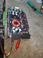
C Audio RA3001 fixed

Here is a a C Audio RA3001 fixed. Stuck in protect. Two MOSFETs blown on Channel 1 and also three small signal transistors shorted.

- Checked all fuses. .. all fine.
-Identitified blown MOSFETs on channel 1 , removed them. Measured as a resistors! Shorted and not open!!
  • Pull out the rail fuses for both channels.
  • switched back on via dim bulb, still stuck in protect..
  • start checking all the signal transistors and diodes, visual check on board too, this takes time and concentration not to miss any...found three shorted transistors (One was a full short across all leads)
  • replaced transistors, checked and checked again, fired up on dim bulb. Comes out of protect , hooray.
  • drain filter caps, insert fuses, fired up and all fine and out of protect still. Just need to replace the two blown MOSFETS.
-DC offset under 10 mV.

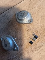
BF423x2, BF422 and two MOSFETs blown.

Not sure what would cause all this to blow like that!

Pic is with three MOSFETs taken out. One was good though.

Attachments

  • 20240513_192255.jpg
    20240513_192255.jpg
    476.8 KB · Views: 81
  • 20240513_192114.jpg
    20240513_192114.jpg
    643.1 KB · Views: 97

DIY Waterproof player for bird songs

Dear audio enthusiasts,

I am new on the forum, and generally new to audio related stuff. Since I'm doing something like this for the first time I'd like to ask for some help in designing and building a small waterproof enclosure for an outdoor speaker. This isn't your typical audiophile project, but more like a simple DIY hobby project of mine. I'm building a small audio device with a single speaker (mono) that will be installed somewhere outside, most likely up on a tree in an open field. The device will periodically play various animal sounds like bird songs and the like. It will be solar-powered, so I will probably want an efficient design to convert maximum amount of energy into sound. The electronics and the PCB are mostly finished - there's a solar battery charger, there's a microcontroller, there's audio data storage, and there's a class-D amplifier IC on the board. I just need to wire up and stuff everything into a box.

I'm having some trouble understanding how to build this box. It's supposed to be waterproof, so wood is likely out of the question. It'll probably be PVC plastic or maybe epoxy/fiberglass, but that's not the main issue. What I'd like to ask about is the shape/size of the box. I've already tried building a test box like a small closed enclosure, but the sound coming out was heavily distorted with some hissing. It sounded like the lower frequencies were more pronounced while the higher frequencies have been cut as if the box acted like a low-pass filter. Then I tried the same speaker with a simple dipole (a plywood board with a hole in the middle), and it worked wonders. There was nice clear sound with no hissing at all. Also, opening the former box did help plenty with the sound quality. Now obviously, I cannot use a flat dipole board directly since it's not waterproof, but I am guessing I will have to use something that is opened on both sides of the speaker to maximize loudness? I also don't want it too big as it's going to be a pain to mount on a tree. Bass and lower frequencies aren't really an issue for this project.

Any suggestions how I should go about?
The speaker I'm using is this one (12 Watt): https://www.cuidevices.com/product/resource/pdf/gf0876m.pdf

Thanks in advance!

Winfield's 100W DC-10MHz 1000V/us amplifier

Rather than continue and extend a fragmented discussion on other threads, I'm starting a new one to discuss my amplifier design, the AMP-70. Fast slew rates are desirable for audiophile amplifiers, for better transient response. My 1000V/us amplifier, which can deliver 100W rms into 8 ohms, could be thought of as an awesome hi-fi amp, but it's really just a laboratory amplifier designed to deliver a full output swing up to 5MHz, even into capacitive loads. (I've included some reduced-size images in this post, the full versions are in the Dropbox folder linked below.)

An externally hosted image should be here but it was not working when we last tested it.


The design is based on the output amplifier in the Tektronix PG508 50MHz pulse generator. We examine this in detail as a Designs-by-the-Masters section in our upcoming book, The Art of Electronics, x-Chapters. I've included this 4-page section in the Dropbox link below. Here's the schematic.

An externally hosted image should be here but it was not working when we last tested it.


Basically there's an input stage creating a push-pull error current into a folded-cascode VAS stage, and emitter-follower outputs. The secret for fast slewing is to use a high 60mA VAS current with low Ccb capacitance transistors, for a fast slew rate S = i/C = 3000V/us for the PG508. The Tek pulse generator only had to deliver 0.2A to its load, whereas I have to deliver 5A, so I'm using larger, higher-capacitance transistors. Following the principle, F.O.M. = Pd / Ccb, to improve the slew rate, I selected low-capacitance types. They're fragile and I'm using 20, to limit their power dissipation.

An externally hosted image should be here but it was not working when we last tested it.


My amplifier design is somewhat more complicated, with various features to increase its capabilities, which we can discuss. Here's a dropbox link to my AMP-70A-2 schematic and related files for you to look over. https://www.dropbox.com/sh/dno89om1uezxs8a/AACoJsLyNazSQZvE9_cTcH4Ja?dl=0

6600 Transformers

I have a set of transformers that I no longer need. Included is one original Eico ST 70 power transformer. Two NEW Eico power transformers built for me by Heyboer. And two 6600 output transformers which are also NEW. I planned to build a pair of KT66 monoblocks and I just don't have the time and too many other projects. I'm asking $500 for the lot.

Attachments

  • Output transformers.jpg
    Output transformers.jpg
    51 KB · Views: 84

Best 8 inch woofer?

Hi guys (and gals),

I have been designing, building and testing speaker systems since the early '70's so I am quite experienced (only for personal pleasure, close friends, family, etc.).

I need a very well designed and great performing 8 inch woofer in the $150 and under range for my next project. I am retired so I think up different designs weekly; sometimes daily!

Box is to be not much larger than 1 ft^3 (28L) and closed design ONLY. This will be a true 3-way; X/O on the low end 200Hz to 400Hz. I'm planning on a 4 to 5 inch fullrange used as a mid from say 200 to well over 4KHz (maybe as high as 6KHz). The tweeter will need to be high output (> 93dB) because of my 60 year old hearing restrictions.

I'm thinking Seas Prestige has the advantage; looking for Fs 20Hz to no more than 27Hz. I have heard HiVi and Aurum Cantus specs. are WAY off! Scan discovery doesn't have any 8 inchers with this low of a Fs.

Comments? Questions? Ideas? Experiences?

This is for a small space only. Vented and TL's are too big for this space. Also, a tuned vented system at say 40Hz will not work since I often listen to pipe organ music. 16Hz on a 40Hz vented will reach X-max at less than 10 Watts. I don't expect deep bass obviously; subs. to come later. If I can get and F3 in the mid. to lower 50's thats good enough!

Thanks!

PART 3 NICHICON / WIMA CAPACITORS, JAPAN SIGNAL RELAYS , TRANSISTORS & IC

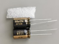
I have for sale some NICHICON / WIMA capacitors , Japan signal relays , audio transistor & IC /

Payment: PAY PAL
Registered priority ( box + antistatic bags )
Shipping to EUROPE 7,5 USD
Rest of the worlds: 8,50 USD
Prices in USD

If you buy for 70 USD or more shipping is free.

Multiple purchases - ONE shipment

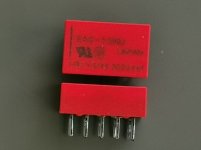
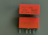
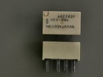
Japan signal relays
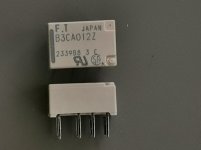
Mfg. NEXEN ( formerly NEC )

1) EA2-12NU 12VDC DPDT Stock: 10 1,26 usd each
2) EC2-12NU 12VDC DPDT Stock: 10 1,26 usd each
3) UC2-5NU 5VDC DPDT miniature Stock: 10 1,26 usd each
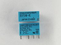
Mfg. TAKAMISAWA
1) FTRBC012 12VDC DPDT miniature Stock: 10 1,41 usd each
2) RY5-WK 5VDC DPDT Stock: 10 2,14 usd each

Attachments

  • DIY EA2 12NU SM.jpg
    DIY EA2 12NU SM.jpg
    55 KB · Views: 43
  • DIY EC2 12NU SM.jpg
    DIY EC2 12NU SM.jpg
    58.8 KB · Views: 41
  • DIY UC2 5NU SM.jpg
    DIY UC2 5NU SM.jpg
    51.7 KB · Views: 46
  • DIY FTRB3 SM.jpg
    DIY FTRB3 SM.jpg
    52.1 KB · Views: 44
  • RY5 małe.jpg
    RY5 małe.jpg
    136.7 KB · Views: 49

PART 2 NICHICON / WIMA CAPACITORS, JAPAN SIGNAL RELAYS , TRANSISTORS & IC

I have for sale some NICHICON / WIMA capacitors , Japan signal relays , audio transistor & IC /

Payment: PAY PAL
Registered priority ( box + antistatic bags )
Shipping to EUROPE 7,5 USD
Rest of the worlds: 8,50 USD
Prices in USD

If you buy for 70 USD or more shipping is free.

Multiple purchases - ONE shipment


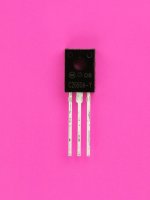
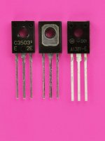
1) KSC2690A-Y ONSEMI TO126 isolated STOCK: 200 0,35 usd each
3) 2SC3503E SANYO TO126 STOCK 200 0,5 usd each
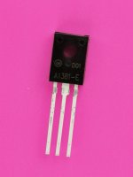
4) KSA1381E ONSEM TO126 isolated STOCK 400 0,41 usd each
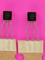
5) KSC1845F ONSEMI TO92 100pcs. STOCK: 400 100pcs. x 0,09 usd = 9 usd
6) KSA992F ONSEMI TO92 100pcs STOCK: 400. 100pcs. x 0,09 usd = 9 usd
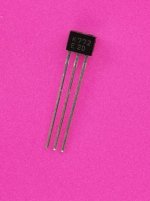
7) 2SK772-E SANYO SPA N-FET STOCK 300 0,45 usd each
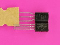
8) 2SC2910-S / 2SA1208-S SANYO TO126MOD STOCK: 200 + 200 0,52 usd 1 NPN + 1 PNP
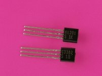
9) 2SC3382-S / 2SA1391-S SANYO TO126 STOCK: 400 + 400 0,44 usd 1 NPN + 2 PNP
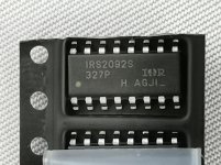
10) IRS2092S INFINEON SOIC 16 STOCK: 15 2,35 usd each
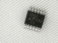
11) LT3045-1 ANALOG D/ LINEAT MSOP STOCK: 5 7,46 usd each
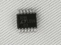
12) LT3094 ANALOG D/ LINEAR MSOP STOCK: 5 7,63 usd each
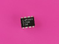
!3) LT1166 ANALOG D. LINEAR DIP8 STOCK: 2 6,55 usd each

Attachments

  • KSC2690AY  SM.jpg
    KSC2690AY SM.jpg
    58 KB · Views: 63
  • 2SC3503 KSA1381  SM.jpg
    2SC3503 KSA1381 SM.jpg
    61.4 KB · Views: 57
  • KSA1381  SM.jpg
    KSA1381 SM.jpg
    64.8 KB · Views: 54
  • Diy KSC1845 KSA992  SM.jpg
    Diy KSC1845 KSA992 SM.jpg
    66.7 KB · Views: 50
  • Diy 2SK772  SM.jpg
    Diy 2SK772 SM.jpg
    63.6 KB · Views: 55
  • Diy 2SC2910 2SA1208  SM.jpg
    Diy 2SC2910 2SA1208 SM.jpg
    61.4 KB · Views: 55
  • 2SC3382 2SA1391 SM.jpg
    2SC3382 2SA1391 SM.jpg
    52.6 KB · Views: 52
  • IRS2092 SM.jpg
    IRS2092 SM.jpg
    81.6 KB · Views: 53
  • LT3045 małe.jpg
    LT3045 małe.jpg
    79.5 KB · Views: 54
  • LT3094 małe.jpg
    LT3094 małe.jpg
    82.1 KB · Views: 53
  • LT1166 SM.jpg
    LT1166 SM.jpg
    44.8 KB · Views: 54

Portable headphone amplifier produces 60hz hum when SOURCE is plugged in to power

(Cross-posted to the headphone forum)

I have this portable "hybrid tube" headphone amplifier. The Little Bear B4-X. I adore it, it sounds just to my liking. It runs on battery power, and I generally use it by plugging it into my phone, ipad or laptop. However, it has a flaw. If it is connected to, let's say, my laptop, and then I plug my laptop in to charge, the headphone amplifier produces a fairly loud 60hz hum through the headphones. When I touch the metal chassis of the laptop, or the metal parts of the 3.5mm audio signal cable leading to the amplifier, or the metal body of the magsafe charging cable, the hum immediately vanishes. Therefore, it is only possible to use the amplifier with a source that is ALSO running on battery power.

I'm not knowledgeable enough to know why this might be, or how I could attempt to fix it. Perhaps there is some modification I can make to the device which will solve this problem?

I have tried reinforcing the chassis ground on the amplifier itself, even adding a second lead from the negative leg of the battery straight to the grounding hole on the PCB. Nothing seems to make any difference. I have some experience building audio electronics from kits. I know my way around a soldering iron. So if I knew WHAT to do, I could certainly do it. I found this sub after a search, and thought maybe someone here could help me.

I welcome any input or suggestions. I've attached a picture of the PCB here, in case it helps. Thanks in advance.

IMG_0943.jpeg

PART 1 NICHICON / WIMA CAPACITORS, JAPAN SIGNAL RELAYS , TRANSISTORS & IC

I have for sale some NICHICON / WIMA capacitors , Japan signal relays , audio transistor & IC /

Payment: PAY PAL
Registered priority ( box + antistatic bags )
Shipping to EUROPE 7,5 USD
Rest of the worlds: 8,50 USD
Prices in USD

If you buy for 70 USD or more shipping is free.

Multiple purchases - ONE shipment


Nichicon capacitors:
KZ series
( PREMIUM GRADE CAPACITORS )
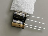
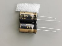
1) 47uF/50V Stock: 100 pcs. 0,30 usd each
2) 100uF/25V Stock: 100 pcs. 0,32 each
3) 100uF/50V Stock: 100 pcs. 0,47 each
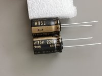
4) 220uF/25V Stock: 100 pcs. 0,519 each
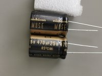
5) 470uF/25V Stock 100 pcs. 0,84 each

FG series ( HIGH GRADE CAPACITORS )
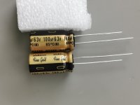
1) 100uF/63V Stock: 100 pcs. 0,72 each

FW series ( STANDARD GRADE CAPACITORS )
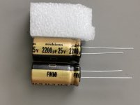
1) 2200/35V Stock: 20 pcs. 1,16 each

KA series ( HIGH GRADE 105C CAPACITORS )
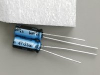
1) 47uF/25V Stock: 200 pcs. 0,222 each

PW series ( low impedance )
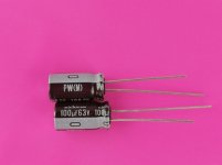
1) 100uF/63V 8 x 15mm Stock: 50 pcs. 0,32 each

WIMA
MKS2 series

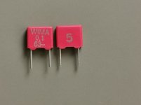
1) 100nF/63V 5% Stock: 200 pcs. 0,24 each
2) 2.2uF/50V 10% Stock: 150 pcs. 0,75 each
FKP2 series
1) 10nF/63V 5% Stock: 150 pcs. 0,297 each

Attachments

  • diy KZ 47 50V SM.jpg
    diy KZ 47 50V SM.jpg
    98.8 KB · Views: 44
  • diy KZ 100 25V SM.jpg
    diy KZ 100 25V SM.jpg
    89.8 KB · Views: 41
  • DIY KZ 100 50V SM.jpg
    DIY KZ 100 50V SM.jpg
    72.7 KB · Views: 42
  • DIY KZ 220 25V SM.jpg
    DIY KZ 220 25V SM.jpg
    74.1 KB · Views: 45
  • DIY KZ 470 25V SM.jpg
    DIY KZ 470 25V SM.jpg
    77.7 KB · Views: 44
  • DIY FG 100 63V SM.jpg
    DIY FG 100 63V SM.jpg
    78.6 KB · Views: 44
  • diy KA 47 25V  SM.jpg
    diy KA 47 25V SM.jpg
    56.4 KB · Views: 40
  • DIY FW 2200 25V SM.jpg
    DIY FW 2200 25V SM.jpg
    58.5 KB · Views: 42
  • PW 100 63V SM.jpg
    PW 100 63V SM.jpg
    53 KB · Views: 37
  • WIMA MKS2 100nF 63 SM.jpg
    WIMA MKS2 100nF 63 SM.jpg
    63.4 KB · Views: 37
  • WIMA MKS2 2.2uF 50V SM.jpg
    WIMA MKS2 2.2uF 50V SM.jpg
    55.8 KB · Views: 40
  • WIMA FKP2 10nF 63V SM.jpg
    WIMA FKP2 10nF 63V SM.jpg
    70.9 KB · Views: 41

KAMU HTR-1 aka project leftovers

I have a quite a lot of unused drivers that were part of an auction I won way back and my ht is still running first gen sony pascals, so I decided to make new ht mains.

The parts are audax tm025f7 titanium tweeters and tannoy 4" pd9ec woofer probably also made by audax. Woofers are used in mercury surrounds and some mission and magnat speakers..
I have 7 woofers and 4 tweeters so I will have some spares at hand after doing the lcr speakers.

I remember that both had pretty flat fr when I measured them a few years ago.

I took out the trusty dayton dats and measured the woofers.

In simulation they seemed to require quite a big box, but I got semi decent results in 7L br tuned box with two woofers per cabinet.

So I opened up fusion and tried to whip out a design that's visually appealing like the sony pascals are.

These will be 3d printed enclosures so I prioritized printability and I also could go wild with the visual design, since no wood working will be involved.

Another goal was to NOT need ANY post processing of the printed parts so I landed on 2 color print with a fuzzy skin surface.

To evaluate the printability and visual design, I printed out a miniature and a full size test print of the top part. The test prints were mandatory also because this is the first time using petg filament for speaker enclosure.

The results were encouraging and print profiles will only need some further adjustments, so I just went ahead designing all the features in fusion 360.

The tweeters will get a printed waveguide and this is the first time I get my hands messy with akabak software.

The crossover will be designed after I have finnished the enclosures and listened the speakers in active config.

Frd and zma files will then be measured in situ and I'm going to try match the active setup as close as possible with the passive x-over.

Let's hope it all goes well, since this is really backwards method compared how I usually design speakers 😅

Attachments

  • Screenshot_2023-10-26-05-20-04-267_com.autodesk.fusion.jpg
    Screenshot_2023-10-26-05-20-04-267_com.autodesk.fusion.jpg
    105.1 KB · Views: 139
  • Screenshot_2023-10-26-05-20-40-826_com.autodesk.fusion.jpg
    Screenshot_2023-10-26-05-20-40-826_com.autodesk.fusion.jpg
    112.7 KB · Views: 140
  • IMG_20231026_052635.jpg
    IMG_20231026_052635.jpg
    494.1 KB · Views: 149
  • IMG_20231023_125741.jpg
    IMG_20231023_125741.jpg
    622.5 KB · Views: 140
  • IMG_20231025_115417.jpg
    IMG_20231025_115417.jpg
    420.7 KB · Views: 146

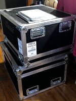
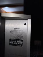
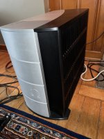
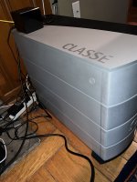
For Sale Classé Omega Monoblocks pair

No longer available


$25k news in 2005

Asking $11500

Attachments

  • IMG_6102.jpeg
    IMG_6102.jpeg
    58.8 KB · Views: 213
  • IMG_5955.jpeg
    IMG_5955.jpeg
    410.5 KB · Views: 211
  • IMG_5633.jpeg
    IMG_5633.jpeg
    387.2 KB · Views: 211
  • IMG_5630.jpeg
    IMG_5630.jpeg
    413.5 KB · Views: 257
  • IMG_5628.jpeg
    IMG_5628.jpeg
    389 KB · Views: 216
  • IMG_5510.jpeg
    IMG_5510.jpeg
    585.6 KB · Views: 213
  • IMG_5625.jpeg
    IMG_5625.jpeg
    425.1 KB · Views: 194
  • IMG_5512.jpeg
    IMG_5512.jpeg
    701.1 KB · Views: 207

good methodology for simulating diffraction with off axis data

hello, I'm currently in the process of designing my first speaker and I find myself blocked with the simulation of diffraction. the drivers i want to use have off axis FR magnitude graphs, respectively 0, 30 and 60 degrees .

The problem is that VituixCad's diffraction simulation tool, while it can give me off axis responses for a given baffle, can only take one FR as an input.

What is the best way to go ? Should I only use the manufacturer's on axis FR and the simulated off axis responses or is there a better way of doing it ?

I was thinking something like using the manufacturer's on axis frequency response to simulate diffraction results between 0 and 30 degrees, using the manufacturer's 30 degrees response to simulate 30 to 60 degrees and so on, but I don't know if that's a valid way of doing it.

Thank you for your time

Teo

Fender Super Bassman 300

Hi folks,
I will have a Super Bassman 300 on my bench within a few weeks. It gives me the time to search for a schematic.
So my question is asked: Anybody with a schematic of this amp?
The problem as far as I've been told is that the auto bias circuit is disabled or even removed. It also need a thorough check-up and a back to factory settings.

Here a picture of the amp.
The Super Bassman CFA7002 is not the one. It has 4 inputs while this amp has only two.
No Deep or Bright switch, only a Vintage/Overdrive.

Thanks for reading and possibly a schematic.
Cheers,

1715598491865.jpeg

12 volt low efficiency, low resolution logic

Heat dissipation and accuracy are all the rave with todays highly portable processors but for basic processing like over and under voltage protection say switching on the power to the main trannie if voltage is either between 80-145volts or 180-290volts and auto selecting primary windings configuration if voltage is above 145volts one can use 12volt logic rather than 3.3volts.
comparator logic.png

Risks? - Headphone out to Line Level In

Hi, wonder if you could help me please? I am curious- I am thinking of using my basic Sony Walkman in my car straight into line level in of my DSP, and my hifi (Denon DM41) hooked up from the headphone out jack to the line level in. A 3.5mm to 2 x RCA cable. I am nervous to do this for one reason. Back in the 1980s, I had a Realistic Karaoke Machine (Concertmate 2000) bought from Tandy here in UK (or Radio Shack in USA). The power output was poor as was the speaker, so I connected it up to my Kenwood Receiver - this again was from the headphone out to the line level in. However, it repeatedly blew internal fuses in the Karakoke machine. Sounded great, but was constantly in the repair shop. I don't understand what fuses blew, but I can remember turning it on and it just made an awful and loud humming noise through the speaker.
So - am nervous to do this again? Is it risky to connect something via headphone out vs line level out?
But more importantly - what wen't on with that machine to blow fuses? My knowledge of electronics is extremely basic - but am curious to understand what was the mismatch that went on there, as people nowadays connect their ipods, ipads, mobile phones to their hifis with the 3.5mm headphone out.
Your help would be really appreciated.
Thanks
Julian

Help with building my first Amp

Hello all: I just registered here, so this is my first post.

I have been debating between buying a Buckeye or VTV class D Hypex Amp. Cost is $1100.

I got to thinking wouldn't it be cool to build my own amp. Unsure if its even possible or what the cost would be.
I want to power my front stage LCR (Emotiva C2+ & Revel Concerta2 F36)

My requirements for the system are 500w x3 channels and a RCA/Banana Plug connectors.

I figure I probably would not even save that much money, but it would be a cool experience.

Can anyone point me in the right direction on where to look, and how to get started?

I have 0 experience with electronics like this. Most experience I have is installing speakers and a head unit in my car. My ONLY soldering experience is soldering a loose speaker wire back onto the speaker chassis.

Would building a 3 channel amp with 250wpc or 500wpc be too much of a undertaking for somebody new?

I am debating between Hypex vs Purifi as well.

Any help you all could provide would be greatly appreciated.

(Side note: What is this forums thoughts on the Texas Instrument Power supplies, being used by Fosi and AIYIMA. Such as the Fosi V3 Mono)


________________________________________________________________________
Edit:
After using the search bar it appears that a kit would be easier.

Apparently " Class D amps use SMD chips" which are not for a beginner.

Any help just pointing me in the right direction would be great !!

Speaker Enclosures for Neo8 Planar Drivers

This must be an FAQ, but I did search this forum for related threads and came up empty. Are there off-the-shelf speaker enclosures routed to mount the 8" Neo-8 drivers? Same dimensions as the GRS 8" planar drivers that Parts Express sells now. I've been running mine using temporary enclosures for far too long, and post-COVID I no longer have access to a shop where I could do the routing myself.

My question is somewhat counter to the DIY ethic, but I love these drivers and would like to finally get them properly mounted.

MOST Bus as a house bus

Really unsure of the best place to put this, but really wanted to document it in case it actually works well!

I've been doing a huge amount of work over the last 18 months or so to try and open up the MOST bus audio system that can be found in cars, eventually creating a MOST bus HAT for a Pi. I am now onto an STM32 based board that will act as a sound card for transmitting audio and control messages.

For a long long time I have been tempted by some multi room audio, and ever since I have been play with the MOST stuff I have been thinking how well it could work with that.

For people that don't know a huge amount about the system, here's a quick overview of it (forgive any numbers being wrong, this is all off the dome!)

MOST is a fibre optic network that has a network master. The network master sets the Fs of the network, either 44.1khz or 48khz. It transmits upto 15 quadlets of synchronous data at once, so allows up to 15 16bit 2 channels streams all at once. A device can stream audio onto the network after negotiation with the master, and any device can retrieve that audio off of the network aswell by setting those quadlets to be assigned to it's own sink.

So here's my thinking of how I can have a play with this.

I've managed to source 10metres of the correct plastic fibre optic cable from ali express for £14, I am going to put a MOST device into everywhere that currently has some type of amplifier (man cave, living room, garage, kitchen), I'm then going to route the cable into each room and build some kind of web app to control the system. So if I am playing audio on my Mac, I will stream that onto 4 channels, if I want that audio picked up in the living room, connect that device to those 4 channels etc etc.

Now I know someone will raise the question and yes I know this is a lot of effort for something that can be done wirelessly these days, but I have a bunch of spare devices that work perfectly well from prototyping etc, also I've grown rather attached to the system, and most importantly - it's going to be great fun!

Anyhow, that's the current thinking, I am happy to keep this post updated if people find it of interest!

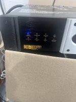
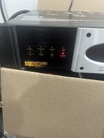
Monster Power HTS 5100MKII Anormal Voltage, Help Please!

Greetings to all, I would like you to help me solve this problem, I have this Monster POWER that was working perfectly, I went to adjust the front brightness to stronger because it was very dim and when I increased the intensity, the Monster Power turned off, it starts to the blue CLEAN POWER ON light flashes and after three seconds the red ABNORMAL VOLTAGE light activates, it flashes for about 3 seconds and the CLEAN POWER ON option is activated again, thus remaining in a loop, three seconds in this option, it goes to the other for three seconds, any idea what's happening? Could you help me solve this problem? Thank you for reading.

Attachments

  • IMG_1044.jpeg
    IMG_1044.jpeg
    460.6 KB · Views: 45
  • IMG_1043.jpeg
    IMG_1043.jpeg
    452 KB · Views: 47

New DIY kit: SEAS Aphel 2 way old school floorstander

For those of us guys, in our best age, who likes old school speakers with large high sensitivity paper midwoofer and wide baffle here it is.

We are goong back to the good old Snell days but with more dynamics and especially details in the treble. The alu dome tweeter sounds indeed good. And you can play loud to.

One of the major benefits with 8 inch and wide baffle is warmer lower midrange and very good punch in the bass. It sounds good with all kind of music.

It is also an easy load for the amp.

Some will comment the power response dip in the crossover area in this and all 8 inch + dome tweeter constructions but to be honest, the sum of advantages will make up for this. And you can barely hear it.

The drivers is as «high end» as you are used to in the HiFi shop, but not expensive though.

Complete drawing and crossover description is here:

https://www.seas.no/index.php?optio...s-aphel-kit&catid=66:seas-diy-kits&Itemid=345

IMG_3140.jpeg

120hz hum in one 845 SE monoblock — what am I missing?

Hi,

I've got some monster 845 SE amps based on the Grover Gardner circuit. (Parallel 6N7 to triode EL34 to 845, SS rectified CLCLCRC. This isn't my troublesome two chassis stereo version of the same circuit I've posted about in other threads.)

When I got them, one had a low level 120hz hum. After using them for two years, I took them to the bench to replace an intermittent power switch. I got overly excited and replaced all of the power supply capacitors (many, given the series caps), changed the filament supplies changed to Coleman regs with transformers to match, swapped in newer and fancier switches and jacks, tidied up some wiring, etc.

After deploying the parts cannon and bringing them back to life, one amp is still very quiet and the other STILL has a low level 120 hz hum.

It could just be unlucky layout on the one side. They are huge, but maybe not huge enough. Maybe the big ground buss arrangement that is fine for one isn't loved by the other. I'm not going to explore major layout changes or a complete rebuild. I could turn the PS chokes 180 degrees, but I can't imagine that would be much help.

I'll keep staring at it until at least next weekend and check all the solder joints again. I'll review some threads about hum, but I've read a lot after battling many humming tube amps. Other random thoughts?

Paul

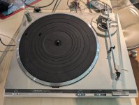
Has Anyone Rewired the Tone Arm on a Technics SL-Q350? One channel has more hum

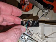
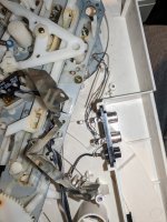
I really like my Technics SL-Q350 turntable other than the higher 60 Hz noise in the right channel. The left channel is great. I want to use it for ripping to digital with the pspacialaudio Stereo Lab software and I'm trying to get an 80 dB SNR in both channels. It uses T4P cartridges that I like, so I am wondering if it is possible to rewire the tone arm at all. The right channel has about 15 dB more hum than the left. I did my best to manage the wires that are easily accessible in the underside of the chassis, twisting the wires for each channel together tightly and keeping them away from other wires had no effect. So the only wire left is in the tone arm and the few inches that go through the gimble. Apparently the wires are far enough apart to create a loop area on just the right channel. The resistance of both channels to the cartridge is the same, around 0.5 ohms. Disassembly looks like hours of work and lots of parts, so I thought I would ask if it's possible to swap wires into that tone arm and T4P head shell?

Attachments

  • Q350.jpg
    Q350.jpg
    176.1 KB · Views: 70
  • Wires before twisting.jpg
    Wires before twisting.jpg
    199.2 KB · Views: 69
  • WiresTwisted.jpg
    WiresTwisted.jpg
    147.1 KB · Views: 69

Totem Hawk crossover design. Why tweeter polarity is reversed?

I bought a pair of Totem Hawk speaker. However, one of the tweeter is blown. And I ordered a new tweeter from my local Totem dealer. I removed the old one and install the new one and found that the original circuit has the polarity reversed. The crossover is a simply first order design. Can anyone tell me why the tweeter polarity is reversed? Also in the tweeter circuit, why do they used three resisters in parallel along with one resister in series? Can them just use one resister? Is it because a specific resistance value that they want to achieve?

thanks a lot in advance

Screenshot 2024-05-10 at 5.34.55 PM.png

Distortion in Measurement Microphones - actual measurements

As there was a lot of discussion about microphone distortion here recently and I'm actually working on a pressure chamber which can produce >160dBSpl ... I spent an afternoon to do some microphone measurements.

Setup
A pressure chamber is a device with a speaker membrane with a very small and 100% sealed front chamber. This pushes the resonance frequency of the 8" speaker to about 350Hz in my case - the volume is that small. But you can produce huge pressure changes now!
Measurements as always done with proper gear (APx515, Class1 Calibrator, Benchmark AHB2 Amp etc).
Measurement frequency is 250Hz (to be sure we are in 100% pressure chamber behaviour and it's the recommended calibration frequency by B&K and GRAS), stepped level sweep, 31 steps.

Check of the chamber - how much THD produces the speaker.
Such a pressure chamber produces stupendous SPL at very little membrane movement - so there is very little THD from the speaker. To check my limits I did the first 2 measurements with a GRAS 1/4" 40BD capsule with 2 different "preamps" (actually just impedance converters, they are just called preamps but there is no amplification).
That's the result.
1-4inch - THD+N Ratio vs Measured Level.PNG

There is a LOT of noise and some strange stuff between 115 and 135dBSpl going on with these 1/4" capsules - legit THD measurements are only starting from 140dBSpl and up. So we produce 150dBSpl with <1%THD and 160dBSpl <3%THD. We don't know if that's the speaker or the refmic! (I have an idea ...)
But we are sure about staying under 1% <150dBSpl and 3% <160dBSpl

So how are our microphones performing.
dBSpl max.png

Here you see the linearity graph. 160dBSpl is easy for our 1/4" capsule. Not so for the other microphones ...
M50 gets to 145dBSpl - spec is 140dBSpl
M215 around 140dBSpl depending on capsule sensitivity -> preamp distortion. Spec is 135dBSpl.
I didn't bother to look after the Behringer Mic spec as it's just here as deterrent example - but >130dBSpl is actually not bad!

But what about THD?!
Here it is - the truth about reference microphone THD:
RefMics - THD+N Ratio vs Measured Level.PNG

As expected ... don't use cheap measurement microphones for delicate measurements. They can't do them. The Behringer is out.
Interesting is that the Earthworks has higher THD as the M215! Noise area is up to about 105dBSpl (there is a lot of noise in the pressure chamber cause of it's sensitivity!!!) but then we get valid measurements. At the specified 140dBSpl max it has already 2% THD - that's A LOT! Studio microphones are normally specified with 0,5% THD, somtimes with 1% when the manufacturer wants to push it a little.
M215 - 135dBSpl is where the preamp starts distorting - that's not a limit of the capsule! Actually - it is when you take the 0,5% THD rule ...
BUT - one of the M215 amplifiers produces more noise as it should. Noise should be less as the M50 (dark green) but number 1 has more noise (light green). Will have to investigate, maybe just dirt in the high impedance area (these mics don't get pampered).

You can calculate your THD from this graph for lower SPL. -20dB -> 1/10th of THD. Even the Behringer follows that rule, it's how a condenser capsule SHOULD behave in theory. And they do!

So what about higher order harmonics?
tbc.

Motor run capacitors

Very early on in my electronics heyday, I was replacing some capacitors in an old RTR I had and I replaced the electrolytic motor capacitors with other electrolytic, of same value. After I was done rebuilding it I ran it and a few seconds later I heard a big pop. That is when I learned that you can’t just put regular old electrolytic capacitors in place of ones rated for motor use. is the case the same for polypropylene? I see that many people now use poly propylene for the capacitors, do they need to be rated for that or pretty much any poly propylene work in that position?

I have a 2.5 µF at 250 V AC and a 6.8 µF at 125 V AC. I know that capacitor is ready for 400 V DC are also rated for 250 V AC, so could I just swap something like this in? Or is it absolutely necessary I get one rated for motor use.
IMG_0890.jpeg

IMG_0891.jpeg


Thank you,
Dan

Amp out as PSU

Hello all, here is a shot in the dark. Please excuse if a stupid question. This is related to my Cub Sandwich sub build

Let's say I wanted to keep the speaker passive and use if with an outboard amp. It's a very small cab in a system sealed by passive radiators. I have designed in a heatpipe to take hot air away from the motor vent. Is there a way to bleed off a lil bit of power from the speaker terminals to power a small fan to encourage air movement in the pipe?

I.e. an active fan inside a passive speaker without any other power supply for the fan

Thanks and regards
Randy

Variations of materials for internal lining, which is the best?

What is the best internal lining for sealed and ducted boxes?
Do sealed boxes really need internal lining?
I once made a sealed box and covered it with glass wool but I was never able to check whether or not it made a difference to the sound.
For ducted boxes with subwoofers intended for deep bass, what coating should I use?

Choosing the right Class D amplifier for me

I'm working on creating a "Wall Sequencer" that let users create their own beats.
I'm trying to get a budget friendly options to build the right Audio Setup.


I'm looking at the following:

The wall will be outside in the open desert.
My goal is to have a clear sound of mostly Electronic (Techno) Instruments, so clear sound and low frequencies are important for me less than volume (power).
I believe the setup should be 2.1 speakers.

Would love to hear your thoughts an ideas on how to get the right Class D for me.
Projects by fanatics, for fanatics
Get answers and advice for everyone wanting to learn the art of audio.
Join the Community
507,708
Members
7,885,245
Messages

Filter

Forum Statistics

Threads
406,085
Messages
7,885,245
Members
507,708
Latest member
ahmadmusowwir