I have a quite a lot of unused drivers that were part of an auction I won way back and my ht is still running first gen sony pascals, so I decided to make new ht mains.
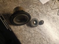
The parts are audax tm025f7 titanium tweeters and tannoy 4" pd9ec woofer probably also made by audax. Woofers are used in mercury surrounds and some mission and magnat speakers..
I have 7 woofers and 4 tweeters so I will have some spares at hand after doing the lcr speakers.
I remember that both had pretty flat fr when I measured them a few years ago.
I took out the trusty dayton dats and measured the woofers.
In simulation they seemed to require quite a big box, but I got semi decent results in 7L br tuned box with two woofers per cabinet.
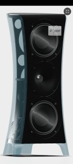
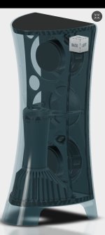
So I opened up fusion and tried to whip out a design that's visually appealing like the sony pascals are.
These will be 3d printed enclosures so I prioritized printability and I also could go wild with the visual design, since no wood working will be involved.
Another goal was to NOT need ANY post processing of the printed parts so I landed on 2 color print with a fuzzy skin surface.
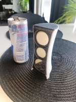
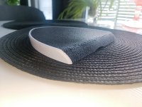
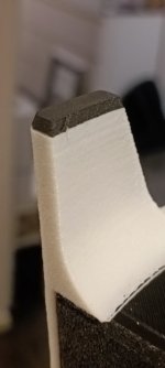
To evaluate the printability and visual design, I printed out a miniature and a full size test print of the top part. The test prints were mandatory also because this is the first time using petg filament for speaker enclosure.
The results were encouraging and print profiles will only need some further adjustments, so I just went ahead designing all the features in fusion 360.
The tweeters will get a printed waveguide and this is the first time I get my hands messy with akabak software.
The crossover will be designed after I have finnished the enclosures and listened the speakers in active config.
Frd and zma files will then be measured in situ and I'm going to try match the active setup as close as possible with the passive x-over.
Let's hope it all goes well, since this is really backwards method compared how I usually design speakers 😅
Attachments
Last edited:
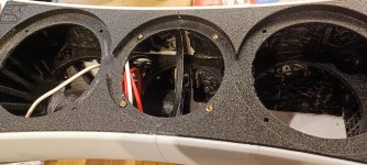
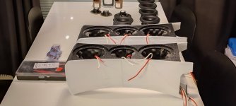
1st half printed. I had a lot of issues with the prime tower snapping, but luckily I was present every time so I fixed that with a 3d pen. Unfortunately the abrubt temperature change of opening the enclosure caused the sheet steel bed to contract causing some minor visual defects on the print. You can see them in the side picture as bulges and crevasses.
The print time for this 1st half was 3days and it took almost 1.5kg of petg.

The print time for this 1st half was 3days and it took almost 1.5kg of petg.
Attachments
First test print of first test wg. Messed up the tweeter interface so I will have to reiterate the 3d model. This is just a little bit scaled down version of audax tw034 waveguide that I'm going to model in akabak and measure in real world to see that I actually know how to use akabak 😀

Prime tower.
It's a dual head printer. The idle head will ooze out stuff that the prime tower catches, then the head prints a layer in it to make sure that the nozzle has material when it carries on to the actual print.
It's a dual head printer. The idle head will ooze out stuff that the prime tower catches, then the head prints a layer in it to make sure that the nozzle has material when it carries on to the actual print.
Hot tip:
Get a decent machine from the get go. Allthough these fit ender3 class machines, it's just a bit too much asked them to print these.
I most definately have to buy one bamboo labs machine and make one bigger printer that's optimized for making speaker enclosures.
Get a decent machine from the get go. Allthough these fit ender3 class machines, it's just a bit too much asked them to print these.
I most definately have to buy one bamboo labs machine and make one bigger printer that's optimized for making speaker enclosures.
Today I got some work done on these:
Installed self adhesive 2mm bitumen to inside walls.
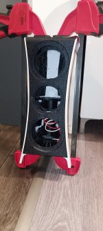
Glued the halves together with bison plastic adhesive. Used some quite large clamps to make sure they're tight.
Installed the heat set inserts with a soldering iron with a dedicated tip
Then I printed out gasgets and feet from varioshore foaming tpu. That tpu let's you foam the stuff so it expands almost 100% making really soft parts.
It seems like my varioshore profile has matured enough to make pretty parts - thank printing gods for that.
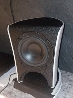
Then I installed the drivers just to see it in one piece and to make some knock tests.
Knock test
Attachments
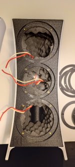
I assembled the speakers and wired them up for active setup for xo design.
First measurements will be made with the stand-in wg. Those results will be verified by modeling the wg in akabak. Then it's time to re-design the wg, when proven that akabak and measurements validate each other.


First measurements will be made with the stand-in wg. Those results will be verified by modeling the wg in akabak. Then it's time to re-design the wg, when proven that akabak and measurements validate each other.
Attachments
Perhaps... I'm not sure if I used stannard 104mm mounting, but I definitely should have!
Last edited:
Wow your design is awesome. It's a realy good Idea to make a tiny model to see how it realy looks like !
I want to make a 15 + 8 + 1 . And I would be intrested in the tw034 waveguide model you seems to have since I want to cnc the waveguide in the front baffle.
By the way. I would be interested in the full 3D of your project since what I have draw looks a bit similar to what you have made. But yours is even better !
Project has been sitting on the desk for a few months now. I made a new wg and this time it's spherical profile. I had to change it so I can get flatter raw response out of the tweet.
I would not look too closely on my old wg. It was just scaled down copy of audax wg. It did not really suit the tweeter as is.
I'm probably going to transform these to a floorstanders with 8“ bass units of opposite contour.
It's going to take a while before I can print out the bass units since my only big printer is suffering from bearing issues and makes horrible noises when driven fast.
- Home
- Loudspeakers
- Multi-Way
- KAMU HTR-1 aka project leftovers
