You are using an out of date browser. It may not display this or other websites correctly.
You should upgrade or use an alternative browser.
You should upgrade or use an alternative browser.
Filters
Show only:
WTB LME49990 x2
Does anyone have a pair of genuine NOS LME49990 they want to sell?
Please PM me.
Thanks!
Please PM me.
Thanks!

Beach Boys: THE Cover to Die For
Just had to share this with fellow fans.
Is the sound quality as good as I think it is??
Login to view embedded media
Is the sound quality as good as I think it is??
Login to view embedded media
How to deburr holes in Aluminium without creating a countersunk drilling?
- By myleftear
- Construction Tips
- 69 Replies
Good afternoon my friends
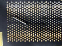
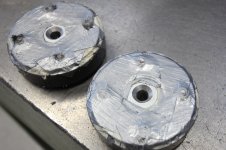
So I may have bungled a bit on my custom top-cover by sheer over enthusiasm.
I drilled all these and was confident the holes would be shard and clean on the upper side, but the all have that tiny little sharp burrmaking it looking and feeling a bit rough.
I want to have them clean and, well, somewhat shiny, but don’t want to make the countersunk by ≈ 1 mm…
The tool I use tends to not bite unless I press so hard that it instantly cuts off too much material.
What should I use? Something to go with a very simple table-drill, or just a hand-tool?
(I was thinking of something that would rather grind than cut, but it’s 2 - 5 mm diameter…)
As you can see, this particular plate already is, erm, failed, but nevermind I fine if I can improve it (better than starting over, right?)
Thank you!
Attachments
SEAS tweeter pole piece drilling
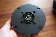
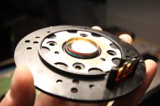
I bought a pair of aluminium dome tweeters SEAS 25 TAF/D (H534-06) in 1993, used them for some years and then stored them for about 20 years. I rediscovered them last summer and did some measurements. On axis frequency response was quite bumpy above 6 kHz and my guess was that the ferrofluid has dried out unevenly and the dome is rocking / tilting at the dampened frequencies.
Resonance frequency according to data sheet should be 1,4 kHz
However impedance curve on data sheet indicates roughly 1,7 kHz
my measurement showed about 2 kHz, maybe because of dry/viscous ferrofluid.
The tweeters were not very usable anymore, so I took the risk and started modifying them to get a usable frequency response and eventually a lower Fs.
Inspiration from troels gravesen
Here is a description of what I did until now:
Required tools:
T20 torx screwdriver
Gaffer tape
Permanent marker
Paper towels and Q-tips
Plastic bags (to protect magnets)
Drill press with sharp metal drill bits and drill lubricating oil
PVA glue
Sine wave generator and amp
Open tweeter:
Mark the position of connectors on the magnet to remember correct assembly! I did not do this and although I am not completely sure I suspect that the parts have one correct fit for exact voice coil centering.
Open the tweeters in a clean enviroment, not in the metal workshop with iron dust and chips everywhere that will be magically attracted into the magnet gap.
Using a T20 torx screwdriver I carefully loosened the front screws, first turning each screw only half a rotation or one and always changing to the opposite screws. Once all screws were removed it was possible to carefully lift the front plate with the glued on diaphragm and voice coil.
The the aluminium domes are quite soft and any dent will produce horrible resonances at high frequencies. Do not ask how I know this – anyway, it was possible to fix it, but there may be some remaining permanent damage.
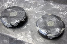
Be careful to avoid any metal particles entering the magnet gap once the tweeter is open! Put the magnet systems in tight plastic bags if you carry them around or if they will be stored.
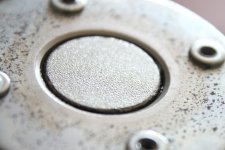
Removing Ferrofluid:
With folded paper and paper towels I removed the ferrofluid from the magnet gap and very carefully also from the voice coil. Q-tips can be helpful here. It may be necessary to repeat this process. I discovered some leftover ferrofluid on the voice coil after some days. Of course, every remaining ferrofluid will affect the impedance curve and frequency response.
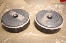
Preparation for drilling pole piece:
Store the front plates with domes and voice coils in a safe place with voice coils upwards!
I cleaned the magnet gap and surrounding to allow the protection tape to stick tightly.
Mark the pole piece center with permanent marker for exact drilling – I did not do this and one hole is slightly off center.
I used several sheets of strong gaffer tape to protect the magnet gap from chips and particles. Leave out or cut out the area for drilling, the drill should not grab or lift the protection tape!
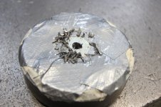
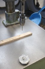
Drilling:
Use protective gloves and glasses!
I did not center punch the pole piece as hitting the magnet may damage the magnet or reduce its magnetic flux.
I used a drill press and sharp metal drills to drill the hole, starting with 5 mm then 6 and 8 mm and finally a countersink drill bit on both sides. I used oil to lubricate the drill. Be careful not to soak and loosen the protection tape adhesive with oil. Drill with gentle pressure. Carefully remove chips to avoid them puncturing the protection tape. Use protective gloves to manually hold the magnet. If the drill gets stuck and rotates the magnet let it go and stop the machine to unscrew the drill from the magnet. Do not clamp the magnet, it is much too brittle and will break!
Cleaning the magnet:
I removed as many metal particles by hand as possible, and used adhesive tape to remove particles from the magnet. With more gaffer tape I covered the existing protection tape above magnet gap to enclose all remaining metal particles.
I filled the gaps between ferrite magnet and iron plates with PVA glue. After it has dired I could remove the glue together with metal particles. Only after the magnet element was completely clean I removed all tape layers above magnet gap at once.
Reassembling
(edited 18.05.2021)
Very carefully align the holes in the front plate to the threaded holes of the magnet. The front plate isroughly self centering and will help avoiding damage to the voice coil when joining the two parts. I used a sine signal generator with 1 and 2 kHz and discovered thougt that the “automatic” centering was not enough at all. (i now realized that the distortion came from a small iron chip in the magnet gap!) It makes sense to assemble the parts with the signal playing so you can immediately hear harmonics when the voice coil is touching the pole pieces. I am actually still struggling to get one of the tweeter voice coils centered properly, it seems to work, but once I tighten the screws the “overtones” come back. (this was the iron chip rubbing the voice coil!)
Again, tighten screws in small steps, always changing between opposite screws.
Remember to temporarily cover the new pole piece hole at the bottom of the tweeter to avoid any (magnetic) particles entering the speaker.
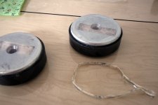
Dampening the pole piece hole
I used acousic felt to experiment with stuffing the pole piece hole. This dampens the helmholtz-resonator effect and protects the opening against dust and metal particles entering to the magnet gap. As may be expected and as you will see in the measurement results, the Helmholtz resonator effect of the hole is very pronounced and results in a deep notch, so I will close the tweeters on the back with a metal sheet or MDF and just use the hole as additional air volume which is enough to lower the resonance frequency reasonably.
My next post will include measurements!
Resonance frequency according to data sheet should be 1,4 kHz
However impedance curve on data sheet indicates roughly 1,7 kHz
my measurement showed about 2 kHz, maybe because of dry/viscous ferrofluid.
The tweeters were not very usable anymore, so I took the risk and started modifying them to get a usable frequency response and eventually a lower Fs.
Inspiration from troels gravesen
Here is a description of what I did until now:
Required tools:
T20 torx screwdriver
Gaffer tape
Permanent marker
Paper towels and Q-tips
Plastic bags (to protect magnets)
Drill press with sharp metal drill bits and drill lubricating oil
PVA glue
Sine wave generator and amp
Open tweeter:
Mark the position of connectors on the magnet to remember correct assembly! I did not do this and although I am not completely sure I suspect that the parts have one correct fit for exact voice coil centering.
Open the tweeters in a clean enviroment, not in the metal workshop with iron dust and chips everywhere that will be magically attracted into the magnet gap.
Using a T20 torx screwdriver I carefully loosened the front screws, first turning each screw only half a rotation or one and always changing to the opposite screws. Once all screws were removed it was possible to carefully lift the front plate with the glued on diaphragm and voice coil.
The the aluminium domes are quite soft and any dent will produce horrible resonances at high frequencies. Do not ask how I know this – anyway, it was possible to fix it, but there may be some remaining permanent damage.
Be careful to avoid any metal particles entering the magnet gap once the tweeter is open! Put the magnet systems in tight plastic bags if you carry them around or if they will be stored.
Removing Ferrofluid:
With folded paper and paper towels I removed the ferrofluid from the magnet gap and very carefully also from the voice coil. Q-tips can be helpful here. It may be necessary to repeat this process. I discovered some leftover ferrofluid on the voice coil after some days. Of course, every remaining ferrofluid will affect the impedance curve and frequency response.
Preparation for drilling pole piece:
Store the front plates with domes and voice coils in a safe place with voice coils upwards!
I cleaned the magnet gap and surrounding to allow the protection tape to stick tightly.
Mark the pole piece center with permanent marker for exact drilling – I did not do this and one hole is slightly off center.
I used several sheets of strong gaffer tape to protect the magnet gap from chips and particles. Leave out or cut out the area for drilling, the drill should not grab or lift the protection tape!
Drilling:
Use protective gloves and glasses!
I did not center punch the pole piece as hitting the magnet may damage the magnet or reduce its magnetic flux.
I used a drill press and sharp metal drills to drill the hole, starting with 5 mm then 6 and 8 mm and finally a countersink drill bit on both sides. I used oil to lubricate the drill. Be careful not to soak and loosen the protection tape adhesive with oil. Drill with gentle pressure. Carefully remove chips to avoid them puncturing the protection tape. Use protective gloves to manually hold the magnet. If the drill gets stuck and rotates the magnet let it go and stop the machine to unscrew the drill from the magnet. Do not clamp the magnet, it is much too brittle and will break!
Cleaning the magnet:
I removed as many metal particles by hand as possible, and used adhesive tape to remove particles from the magnet. With more gaffer tape I covered the existing protection tape above magnet gap to enclose all remaining metal particles.
I filled the gaps between ferrite magnet and iron plates with PVA glue. After it has dired I could remove the glue together with metal particles. Only after the magnet element was completely clean I removed all tape layers above magnet gap at once.
Reassembling
(edited 18.05.2021)
Very carefully align the holes in the front plate to the threaded holes of the magnet. The front plate is
Again, tighten screws in small steps, always changing between opposite screws.
Remember to temporarily cover the new pole piece hole at the bottom of the tweeter to avoid any (magnetic) particles entering the speaker.
Dampening the pole piece hole
I used acousic felt to experiment with stuffing the pole piece hole. This dampens the helmholtz-resonator effect and protects the opening against dust and metal particles entering to the magnet gap. As may be expected and as you will see in the measurement results, the Helmholtz resonator effect of the hole is very pronounced and results in a deep notch, so I will close the tweeters on the back with a metal sheet or MDF and just use the hole as additional air volume which is enough to lower the resonance frequency reasonably.
My next post will include measurements!
Attachments
Ballpark PSRR value to be expected in a tube push-pull power output stage
- By SomeJoe
- Tubes / Valves
- 19 Replies
Hello,
As per title, what kind of PSRR value is to be expected from a typical push-pull power output stage, say a 6L6 in regular transformer-coupled circuit without negative feedback, perhaps in a realistic situation where tubes age and the stage might not be perfectly balanced ?
I just need a rough ballpark figure to estimate how crazy I have to get on power supply ripple filtering; the input stage will be regulated.
Thanks in advance,
Joris
What's the average high-voltage supply voltage in tube amps, in general?
- By Perry Babin
- Tubes / Valves
- 73 Replies
For example, a 50w/channel amp for 8 ohms?
A 100w/channel amp for 8 ohms?
A 100w/channel amp for 8 ohms?
Hi, everyone!
- By Phoner
- Introductions
- 2 Replies
Hi everyone, I am a not a new member to this forum. All this time I have been more of an observer. This is my first post here to introduce my self. Vintage audio is my passion.
Let me introduce myself
- By howlndog
- Introductions
- 4 Replies
My name is Derek and I’m a long time lurker. I’m a retired landscape architect that likes to build stuff. To date I’ve built a Lenco turntable and 2 sets of speakers… and a pair of subwoofers. My speaker building started when I bought a CNC router… cause I can’t cut a straight line on my own. My next project will be a pair of Bagby Kairos, assuming Meniscus makes the crossover design available. If not that… I’m not sure what.


Open Source Image Control Waveguide
- By LogDew
- Introductions
- 17 Replies
Hi everyone,
I have been trying to build a clone of the JBL M2 reference monitors. But i have been having problems with finding a "cheep" or open source version of the JBL image control waveguide. I did read through the other posts on cloning the JBL M2 but was unable to make a waveguide that works. I plan to use the SB Audience ROSSO 65CD-T 1.4 inch compression driver as the tweeter and the Eminence Kappalite 3015LF 15 inch woofer. The box will be identical to the original because the Eminence woofer has an identical set of Thiele Small parameters. Thanks in advance for the help in designing an open source image control waveguide.
I have been trying to build a clone of the JBL M2 reference monitors. But i have been having problems with finding a "cheep" or open source version of the JBL image control waveguide. I did read through the other posts on cloning the JBL M2 but was unable to make a waveguide that works. I plan to use the SB Audience ROSSO 65CD-T 1.4 inch compression driver as the tweeter and the Eminence Kappalite 3015LF 15 inch woofer. The box will be identical to the original because the Eminence woofer has an identical set of Thiele Small parameters. Thanks in advance for the help in designing an open source image control waveguide.
Has anyone tried this DAC?
- By zintolo
- Digital Line Level
- 9 Replies
I’ve found this DSD DAC, has anyone used it?
https://www.ebay.com/itm/156272946801
Thank you in advance.
https://www.ebay.com/itm/156272946801
Thank you in advance.
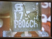
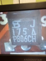
Soundstream rubicon 502
When I supply power (no remote) all 3 led's turn on. I opened it up and found Q41 is bad. Does anyone know where to find this or something i can replaceit with? I can't even get a datasheet.
Attachments
Potential GB for original PCB set for the F5Pi
- By EUVL
- Group Buys
- 55 Replies
We have already posted the Gerber files for the frontend and the OPS of the F5Pi.
So anyone can build them with their own power supplies, etc.
But there are some interest also in duplicating our build 1:1.
So we shall offer a complete set of our PCBs, plus BoM, plus instructions, as follows.
The instructions really mean A LOT of work for me and especially for Fran.
So we shall only offer this when the subscription exceed 10 sets.
Each PCB set will include :
2x F5P frontend PCB (mirrored L&R versions with additional features such as BA3 compatibility)
2x M2OPS PCB (mirrored L&R versions)
2x C_Reg_C PCBs for frontend (LM317/337 or equivalent)
2x C_Reg_C++ PCBs for the OPS (2x LM338)
4x TO220 rectifier PCBs
2x Aux. PSU's
1x Power Push-button PCB
2x LED strip PCB
2x Source select / volume control relay board (mirrored)
1x Relay driver board
1x Relaixed controller board with pre-programmed MCU
2x Improved DC Protection board with start-up delay and rail-loss protection, mirrored version
1x Printed BoM and instructions.
Total cost will be 120€ + postage, shipped from Ireland.
So they already include EU VAT and import charges.
Thank you for your support and interest,
Patrick
Otari MX-5050 1/4" 2 Track High End Drop Outs
- Analogue Source
- 2 Replies
Hey all! Hoping those of you wiser than me could offer an opinion.
I've had my Otari MX-5050 for a few years, purchased from someone who bought it new and babied it. It works wonderfully and I keep up with maintenance and alignment (I do myself with an MRL tape), but it's had a strange very intermittent issue since purchased.
The left channel, when in record, will randomly experience a dropout of the high end, feels like around 7kHz all the way up, and this issue will come and go within 30-60 seconds. Happens infrequently but enough that it becomes an issue on mixdown.
It happens with different rolls of tape, after cleaning heads, ect., anyone have ideas? Is this a tape path issue? Excess resistance due to dirty contacts?
Thank you for reading, and happy listening!
WTB Upgrade Parts for a Parasound HCA-3500 (Holco, PR9372, Diotec bridges, etc)
Thanks to members on the forum, I was able to fix a bad channel on a Parasound HCA-3500 and want to recap it and perform some of the modifications recommended by Big Sky Audio and John Curl. I have a Mouser cart for replacing the electrolytics in the audio path with newer Panasonic and Nichicon caps, but trying to track down some of the resistors and bypass caps.
Before searching for all parts, I wanted to see if anyone has some parts they purchased but decided not to use.
These are a few of the items I am not able to get on Mouser. The unit already has Rubycon Black Gates in C7, C8, C12, and C13.
Thank you.
Before searching for all parts, I wanted to see if anyone has some parts they purchased but decided not to use.
- Holco H4 Resistors (47k)
- PR9372 Resistors (2.2k)
- Rel-Cap RT capacitors
- Diotec Soft Recovery Bridge Rectifiers
These are a few of the items I am not able to get on Mouser. The unit already has Rubycon Black Gates in C7, C8, C12, and C13.
Thank you.
Bias adjustment problem on original AEM6000 amp
- By astro164
- Solid State
- 16 Replies
Hi Guys,
I had built the original AEM6000 (David Tilbrook) amp modules, power supplies, status monitors and surge current limiter many years ago.
I have now decided to finish this project by testing the amp modules before I install everything in its case.
On one amp module everything is good, bias current adjustment as per instructions is 2.6v across the 10ohm 5w series resistors.
However the other module can only be adjusted to 2.3v... I have changed the original 200ohm Phier trim pot with the same brand and spec - still only getting the 2.3v.
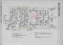
I have attached the circuit diagram with my measurements in green and maybe someone can give me some advice on what is going on.
Please note my wall voltage is around 248v AC.
Any help would be appreciated.
Peter
I had built the original AEM6000 (David Tilbrook) amp modules, power supplies, status monitors and surge current limiter many years ago.
I have now decided to finish this project by testing the amp modules before I install everything in its case.
On one amp module everything is good, bias current adjustment as per instructions is 2.6v across the 10ohm 5w series resistors.
However the other module can only be adjusted to 2.3v... I have changed the original 200ohm Phier trim pot with the same brand and spec - still only getting the 2.3v.
I have attached the circuit diagram with my measurements in green and maybe someone can give me some advice on what is going on.
Please note my wall voltage is around 248v AC.
Any help would be appreciated.
Peter
Attachments
Parasound HCA 3500 -- Part it out or Get it fixed?
- By Dneu2011
- Solid State
- 76 Replies
I just traded a friend for a Parasound HCA-3500 amp with a dead left channel.
My original plan was to scrap it for parts and use the chassis for an Aleph JZM build but I wanted to first see if it’s worth trying to fix.
Here is what I found out:
Left channel relay does not click.
If I unplug the psu from the left channel it clicks on and I can see that the B+ and B- voltages are correct.
Every fuse on that left channel was removed and tested for continuity
I performed a diode check on each output transistor when still connected and they seemed to all be fine.
I am torn between the three options below:
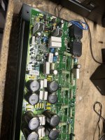
I am located in Houston, TX. Below are pics of the inside of the amp after removing the left channel and a pic of the left channel (I had removed one of the 100uf caps for testing)
My original plan was to scrap it for parts and use the chassis for an Aleph JZM build but I wanted to first see if it’s worth trying to fix.
Here is what I found out:
Left channel relay does not click.
If I unplug the psu from the left channel it clicks on and I can see that the B+ and B- voltages are correct.
Every fuse on that left channel was removed and tested for continuity
I performed a diode check on each output transistor when still connected and they seemed to all be fine.
I am torn between the three options below:
- Part it out and use the chassis for an Aleph JZM (I have every part to build this amp)
- Part it out and use the chassis for an F5 Turbo V2 (because of the chassis size, but I do not have any of the parts)
- Take it to get it fixed but our local tech charges quite a bit (guessing anywhere from $350-$600 to fix)
I am located in Houston, TX. Below are pics of the inside of the amp after removing the left channel and a pic of the left channel (I had removed one of the 100uf caps for testing)
Attachments

Help needed! Wide band noise (sounds like radio white noise) in audio when powering Dac with this Power Supply
- By CLiu
- Power Supplies
- 3 Replies
Hi All,
I made a DC power supply board to power my Dac. The topology is as follows:
+15V: 5V input from USB Charger -> TPS61085 DC to DC converter (+17V) -> LM2941 Regulator (+15V) -> Output
-15V: 5V input from USB Charger -> TPS61085 DC to DC converter (+17V) -> Charge Pump (-16.5V) -> LM2991 Regulator (-15V) -> Output
I measured the output voltage with a DMM (that's the only test equipment I have), and the result were as per design. However, when turning the power on, I heard a constant noise (not very loud, but audible within a few ft. from the board). Note that the board is not connected to any load, just 5V power from USB charger. Not sure how to describe the noise, but it does not sound like whining noise, but a bit like rapid mechanical vibration. I did not pay too much attention to it at that time. To me surprise, when I connected the power supply to the dac and the rest of the system, I hear a kind of wideband noise at the speakers. It sounds like random radio / TV noise, or gentle rain hitting at the roof. At a volume level setting that usually gives 70-80dB SPL, I could hear it faintly at my listening position about 9 ft. away from the speakers.
I don't get this noise when using a different power supply that uses AC transformer and LDO. So it is quite obvious that the noise appeared because of this power supply. I do not have a lot of knowledge / experience in electronics. Just attempted to design and implement a DC power supply after doing some research on the internet. The circuit is done based on recommendations in the datasheets of the switcher and ldo. I think I must have missed some very important design rules.
1. Can anyone have a look at the schematics and shed some light on what could have gone wrong?
2. I did not have separate ground planes for the switcher and ldo. Would it help if they use separate ground planes? If yes, how should the ground planes be connected, e.g. using ferrite bead / capacitor?
Best regards
Liu
World's Best Tweeters Face-off :: Subjective comparison
I had a great opportunity this week (thanks to Chris at Solen): Side-to-side comparison with 3 of the greatest tweeters on the planet, from the Serbian company RAAL:
.: The super efficient 210-10D ''Lazy ribbon''
.: The renowned 140-15DAM (amorphous core version)
.: and the not-available-to-public 70-20XR
Over the years i had the chance to play, test and listen to each of them for many hours, but i never had the opportunity to make a comparison test, side-to-side, using the very same system and room and keeping the memory fresh with same music excerpts.
So, here it is.
As you can see, i added a little intruder: a ''value'' tweeter, the surprising Airborne RT-4001... just to have a ''non-Raal'' driver as a reference...
Before i start, here is a quick presentation of the system: it's an active 4-way that uses DEQX preamp/DSP/xover + ICEpower amplifiers + macMini/itunes music server that feeds digitally the DEQX. Other drivers are: (4) JL audio 10w7 + (2) Volt midbass + (2) Voxativ AC-1.6.
EQ calibration made from the listening seat, distance of 4.8 meters and about 8 deg off-axis using Earthworks M50 calibrated mic.
The Voxativ was the perfect midrange for this test because it's a fullrange/wideband that is really at ease with pretty much any highpass xover point i had to try...
First, i did a little test to see what they have in the belly, their comfort zone, their natural in-room frequency response. For that, i made a DEQX highpass setting of 1000hz with very steep 162db/octave linear phase.
Then, based on the results, i made other DEQX configurations, EQ'd the FR and listened to each of them. I kept the EQing very light so the real sonic signature of each tweeters stays realistic.
Most of the time it was with a 300db/oct slope linear phase, so if you're using passive set-up your results/conclusions may be different than mine, but i think, overall, it gives a good idea of each drivers. It's subjective, of course, but i'll do my best to stay objective ;-)
AIRBORNE RT-4001
Lower Frequencies: 7.0/10
Higher Frequencies: 6.5/10
Micro/Macro dynamics: 6.5/10
3D feeling and Texture: 7.0/10
Transparency: 7.5/10
Ease of integration: 7.5/10
CONCLUSIONS: The overall performance of this inexpensive tweeter is very good. In fact, it's surprising how good it performs in this somewhat unfair comparison. Comfort zone from 2,5khz up to 14khz... FR not too bumpy... handles well the EQ corrections... Not a lot of energy but very decent... a little ''sssssss'' sonic signature that reminds us we have tweeters in the systems, but i've seen a lot worst.
----------------------------------------------------------
RAAL 140-15DAM
Lower Frequencies: 9.0/10
Higher Frequencies: 8.5/10
Micro/Macro dynamics: 8.5/10
3D feeling and Texture: 8.5/10
Transparency: 9.5/10
Ease of integration: 9.5/10
CONCLUSIONS: Considered by many as THE best tweeter in the world, i have to admit this one has no weakness. Like.. at all. It's, by far, the most well-balanced high-frequency driver i heard in my life so far. It disappear completely while keeping the razor sharp resolution you expect... natural FR is excellent... handles EQ correction like a champ... Comfort zone 1.6khz - 20khz+ makes it very easy to match with almost any midrange driver.
----------------------------------------------------------
RAAL 70-20D
Lower Frequencies: 9.5/10
Higher Frequencies: 8.0/10
Micro/Macro dynamics: 8.0/10
3D feeling and Texture: 8.5/10
Transparency: 9.5/10
Ease of integration: 9.0/10
CONCLUSIONS: Rumor was floatting about this not-available to public driver that it could beat his mighty brothers... Well, i wouldnt say that but some might find it indeed better, in some ways... Comfort zone 1.6khz - 10khz with a surprising roll-off smoothly starting from 8khz, that is the ribbon tweeter that sounds the least like a ribbon tweeter. Very ''domish'' sonic signature, if i may say. Would probably compete well against high-end domes such as the big Scan-speak and such. Because of his discreet high frequencies, it's very transparent while keeping a very good resolution feeling. High frequencies are there, but never annoying. Lower frequencies (+/- 1.6khz-5khz) is on par with the 140-15D or even better.
----------------------------------------------------------
RAAL 210-10D
Lower Frequencies: 5.5/10
Higher Frequencies: 9.5/10
Micro/Macro dynamics: 9.5/10
3D feeling and Texture: 9.0/10
Transparency: 9.0/10
Ease of integration: 4.5/10
CONCLUSIONS: As you can see, that's a wild one. Comfort zone from 3.8khz (and more likely 5 or 6khz) One of the most painful driver i had to integrate. Bumpy FR and limited bandwith. Nasty peak between 12khz and 17khz, dip at 7khz, another peak at 4khz... Not to mention the laser-narrow directivity. Doesnt look like i appreciate it very much, is it ? Well, on the contrary. With the right mid (which i have) you can take a chance with this stallion. The micro dynamics are out of this world, you have a 3D feels that add depth in almost every music you listen to... More resolution, more texture, more audio porn. Like a marriage with a Victoria secret's model, it might very well end up in a divorce, but you may also enjoy the ride.
-----------------------------------------
Unfortunately, no clear winner. It really depends of your needs and tastes. But i think that's some good information to start with, i hope it can help a little...
Next: i may try the Beyma tweeters 🙂
Jon
P.S. all drivers specs are available on the new Solen website: Home | Solen Electronique - World leading producer of high-end crossover components
-------------------------------------------------------------------------------
***EDIT ADD-ON 24 december 2016***
-------------------------------------------------------------------------------
BEYMA TPL 150 H
Lower Frequencies: 7.5/10*
Higher Frequencies: 6.0/10
Micro/Macro dynamics: 7.5/10
3D feeling and Texture: 7.0/10
Transparency: 8.0/10
Ease of integration: 8.5/10
CONCLUSIONS: A bit of a disappointment, i must say. Not a bad tweeter at all, just not as good as a 4in. diaphragm compression in the mid-hi region, and surely not able to compete in the last 2 octaves against the RAAL ribbons. On the other hand they are quite efficient, you can cross it low, they don't have any obvious flaws, they are pretty good jack-of-all-trades performers and probably more interesting than most of the dome technology tweeters there is.
*didn't try lower crossover point than 2.2khz and without a proper installation on a baffle, so the lower-frequencies (1khz-4khz) was not properly tested and mainly just compared to the Radian 950BPbe's midrange performance in that bandwith (in which the Beyma completely lost in comparison).
.: The super efficient 210-10D ''Lazy ribbon''
.: The renowned 140-15DAM (amorphous core version)
.: and the not-available-to-public 70-20XR
Over the years i had the chance to play, test and listen to each of them for many hours, but i never had the opportunity to make a comparison test, side-to-side, using the very same system and room and keeping the memory fresh with same music excerpts.
So, here it is.
An externally hosted image should be here but it was not working when we last tested it.
As you can see, i added a little intruder: a ''value'' tweeter, the surprising Airborne RT-4001... just to have a ''non-Raal'' driver as a reference...
Before i start, here is a quick presentation of the system: it's an active 4-way that uses DEQX preamp/DSP/xover + ICEpower amplifiers + macMini/itunes music server that feeds digitally the DEQX. Other drivers are: (4) JL audio 10w7 + (2) Volt midbass + (2) Voxativ AC-1.6.
EQ calibration made from the listening seat, distance of 4.8 meters and about 8 deg off-axis using Earthworks M50 calibrated mic.
The Voxativ was the perfect midrange for this test because it's a fullrange/wideband that is really at ease with pretty much any highpass xover point i had to try...
First, i did a little test to see what they have in the belly, their comfort zone, their natural in-room frequency response. For that, i made a DEQX highpass setting of 1000hz with very steep 162db/octave linear phase.
An externally hosted image should be here but it was not working when we last tested it.
Then, based on the results, i made other DEQX configurations, EQ'd the FR and listened to each of them. I kept the EQing very light so the real sonic signature of each tweeters stays realistic.
Most of the time it was with a 300db/oct slope linear phase, so if you're using passive set-up your results/conclusions may be different than mine, but i think, overall, it gives a good idea of each drivers. It's subjective, of course, but i'll do my best to stay objective ;-)
AIRBORNE RT-4001
Lower Frequencies: 7.0/10
Higher Frequencies: 6.5/10
Micro/Macro dynamics: 6.5/10
3D feeling and Texture: 7.0/10
Transparency: 7.5/10
Ease of integration: 7.5/10
CONCLUSIONS: The overall performance of this inexpensive tweeter is very good. In fact, it's surprising how good it performs in this somewhat unfair comparison. Comfort zone from 2,5khz up to 14khz... FR not too bumpy... handles well the EQ corrections... Not a lot of energy but very decent... a little ''sssssss'' sonic signature that reminds us we have tweeters in the systems, but i've seen a lot worst.
----------------------------------------------------------
RAAL 140-15DAM
Lower Frequencies: 9.0/10
Higher Frequencies: 8.5/10
Micro/Macro dynamics: 8.5/10
3D feeling and Texture: 8.5/10
Transparency: 9.5/10
Ease of integration: 9.5/10
CONCLUSIONS: Considered by many as THE best tweeter in the world, i have to admit this one has no weakness. Like.. at all. It's, by far, the most well-balanced high-frequency driver i heard in my life so far. It disappear completely while keeping the razor sharp resolution you expect... natural FR is excellent... handles EQ correction like a champ... Comfort zone 1.6khz - 20khz+ makes it very easy to match with almost any midrange driver.
----------------------------------------------------------
RAAL 70-20D
Lower Frequencies: 9.5/10
Higher Frequencies: 8.0/10
Micro/Macro dynamics: 8.0/10
3D feeling and Texture: 8.5/10
Transparency: 9.5/10
Ease of integration: 9.0/10
CONCLUSIONS: Rumor was floatting about this not-available to public driver that it could beat his mighty brothers... Well, i wouldnt say that but some might find it indeed better, in some ways... Comfort zone 1.6khz - 10khz with a surprising roll-off smoothly starting from 8khz, that is the ribbon tweeter that sounds the least like a ribbon tweeter. Very ''domish'' sonic signature, if i may say. Would probably compete well against high-end domes such as the big Scan-speak and such. Because of his discreet high frequencies, it's very transparent while keeping a very good resolution feeling. High frequencies are there, but never annoying. Lower frequencies (+/- 1.6khz-5khz) is on par with the 140-15D or even better.
----------------------------------------------------------
RAAL 210-10D
Lower Frequencies: 5.5/10
Higher Frequencies: 9.5/10
Micro/Macro dynamics: 9.5/10
3D feeling and Texture: 9.0/10
Transparency: 9.0/10
Ease of integration: 4.5/10
CONCLUSIONS: As you can see, that's a wild one. Comfort zone from 3.8khz (and more likely 5 or 6khz) One of the most painful driver i had to integrate. Bumpy FR and limited bandwith. Nasty peak between 12khz and 17khz, dip at 7khz, another peak at 4khz... Not to mention the laser-narrow directivity. Doesnt look like i appreciate it very much, is it ? Well, on the contrary. With the right mid (which i have) you can take a chance with this stallion. The micro dynamics are out of this world, you have a 3D feels that add depth in almost every music you listen to... More resolution, more texture, more audio porn. Like a marriage with a Victoria secret's model, it might very well end up in a divorce, but you may also enjoy the ride.
-----------------------------------------
Unfortunately, no clear winner. It really depends of your needs and tastes. But i think that's some good information to start with, i hope it can help a little...
Next: i may try the Beyma tweeters 🙂
Jon
P.S. all drivers specs are available on the new Solen website: Home | Solen Electronique - World leading producer of high-end crossover components
-------------------------------------------------------------------------------
***EDIT ADD-ON 24 december 2016***
-------------------------------------------------------------------------------
BEYMA TPL 150 H
Lower Frequencies: 7.5/10*
Higher Frequencies: 6.0/10
Micro/Macro dynamics: 7.5/10
3D feeling and Texture: 7.0/10
Transparency: 8.0/10
Ease of integration: 8.5/10
CONCLUSIONS: A bit of a disappointment, i must say. Not a bad tweeter at all, just not as good as a 4in. diaphragm compression in the mid-hi region, and surely not able to compete in the last 2 octaves against the RAAL ribbons. On the other hand they are quite efficient, you can cross it low, they don't have any obvious flaws, they are pretty good jack-of-all-trades performers and probably more interesting than most of the dome technology tweeters there is.
*didn't try lower crossover point than 2.2khz and without a proper installation on a baffle, so the lower-frequencies (1khz-4khz) was not properly tested and mainly just compared to the Radian 950BPbe's midrange performance in that bandwith (in which the Beyma completely lost in comparison).
Is Talon Electronics a valid parts source?
I am working on a Harman Kardon 330C receiver for a friend, he put the wrong bulb in the FM stereo light and fried the power supply transistor Q1 (2SD414) for the tuner board. I found Talon Electronics, based in Virgina, on a Google search. They have a few of these in stock for a good price.
https://talonelectronics.com/shop/
I have never heard of them I wondered if anyone here has purchased from them.
I am also considering BD237 or MJE243 from Digikey but an exact replacement would be preferable.
https://talonelectronics.com/shop/
I have never heard of them I wondered if anyone here has purchased from them.
I am also considering BD237 or MJE243 from Digikey but an exact replacement would be preferable.
AMT for line array
- By Neil Davis
- Planars & Exotics
- 7 Replies
I needed 48 tweeters to make a 65" line array, so I can up with a very simple design that I can make quickly. I use purchased diaphragms, some perforated sheet and some readily available 3mm x 10mm x 60mm magnets. I am putting the tweeters in groups of 4 to make assembly easier. The array will use electronic curvature with a 24-channel DSP/amp shown in the last photo.
I've only made one tweeter so far, but it looks like this design will work just fine.

Online metals has .106" thick perforated steel sheets with 51% open area. I used a Ryobi flooring saw with a 5-3/8" steel-cutting blade to slice up the sheets. That worked a lot better than I expected, without making a mess.
After a small amount of sanding the cut lines, I painted the cut plates and glued on the magnets with epoxy. The diaphragms were round, but I used a bench sander to allow closer spacing. The housing for the diaphragms measure about 2.7mm thick, so the 3mm magnets work great.

And then CAREFULLY put on the top grid. You need to watch your fingers because the pieces will try to snap together violently.

The prototype works, and I only have to make 23 more 🙂. Notice that this can be used as a dipole, which is what I intend to do for this line array. The midrange array will have 28 TC6 2" drivers on each side, along with a 12" ripole woofer for each array.
The DSP/amp is done, and all the channels work and can be individually controlled. However, it still needs more code to control the curvature and shading. The ripole woofers will have their own amps. There is more info on the DSP/amp at this link: http://www.audiodevelopers.com/2024/03/17/another-prototype-line-array-amp/

I've only made one tweeter so far, but it looks like this design will work just fine.
Online metals has .106" thick perforated steel sheets with 51% open area. I used a Ryobi flooring saw with a 5-3/8" steel-cutting blade to slice up the sheets. That worked a lot better than I expected, without making a mess.
After a small amount of sanding the cut lines, I painted the cut plates and glued on the magnets with epoxy. The diaphragms were round, but I used a bench sander to allow closer spacing. The housing for the diaphragms measure about 2.7mm thick, so the 3mm magnets work great.
And then CAREFULLY put on the top grid. You need to watch your fingers because the pieces will try to snap together violently.
The prototype works, and I only have to make 23 more 🙂. Notice that this can be used as a dipole, which is what I intend to do for this line array. The midrange array will have 28 TC6 2" drivers on each side, along with a 12" ripole woofer for each array.
The DSP/amp is done, and all the channels work and can be individually controlled. However, it still needs more code to control the curvature and shading. The ripole woofers will have their own amps. There is more info on the DSP/amp at this link: http://www.audiodevelopers.com/2024/03/17/another-prototype-line-array-amp/
Question about Lambda Labs MF15A
- By Selfie
- Subwoofers
- 5 Replies
Hello everyone..
I don’t want to advertise a product! Just a question because I search for light weight deep 15“ sub..
And I found the mf15a or the Seeburg gsub 1501. lambda labs termed the mf15a as a manifold sub but I just see a driver on a skewed baffle directed to the floor and some big ports.
What do you think about it? Why some folks say it’s a bandpass? Maybe I want to build something similar with 18“ 🙂
Best regards
https://www.lambda-labs.com/de/produkte/mf-15a
Isobaric coupling a woofer to a PR?
- Subwoofers
- 7 Replies
Greetings!
I've recently encountered some older articles about a particular subwoofer design by James Loudspeakers - their EMB line of subwoofers:
https://www.stereophile.com/subwoofers/904james/index.html
https://www.jamesloudspeaker.com/products/118

The "energy multiplier" sounds a bit ridiculous to me, but I guess this is just marketing talk. From what I could gather so far this seems to be a single-reflex bandpass enclosure that uses a passive radiator instead of a port or vent. However, since the front chamber is sealed, it seems to work more like an isobaric arrangement without the second motor unit.
What would be the advantages and disadvantages in this case other than potentially halving the Vas, resulting in a smaller enclosure? Has anyone experimented with this type of design before?
Ordered a few passive radiators to test this with the woofers I have laying around. I'm planning on testing with a small 4" TCP115-4 from Dayton and a bigger 8" subwoofer driver to see what the results will be. Trying to wrap my head around how to calculate the enclosures properly. Any and all advice would be very much appreciated!
I've recently encountered some older articles about a particular subwoofer design by James Loudspeakers - their EMB line of subwoofers:
https://www.stereophile.com/subwoofers/904james/index.html
https://www.jamesloudspeaker.com/products/118
The "energy multiplier" sounds a bit ridiculous to me, but I guess this is just marketing talk. From what I could gather so far this seems to be a single-reflex bandpass enclosure that uses a passive radiator instead of a port or vent. However, since the front chamber is sealed, it seems to work more like an isobaric arrangement without the second motor unit.
What would be the advantages and disadvantages in this case other than potentially halving the Vas, resulting in a smaller enclosure? Has anyone experimented with this type of design before?
Ordered a few passive radiators to test this with the woofers I have laying around. I'm planning on testing with a small 4" TCP115-4 from Dayton and a bigger 8" subwoofer driver to see what the results will be. Trying to wrap my head around how to calculate the enclosures properly. Any and all advice would be very much appreciated!
PD 18BR40 rattle noise
- By skogs
- Subwoofers
- 5 Replies
One of my 18BR40 has developed a rattling noise when playing 20-80hz at moderate levels. It seems that the rattling follows the excursion. If i lightly touch the cone while its playing, the rattle goes away. The pitch changes slightly if i adjust the bolts holding the driver in the box. The rattle is barely audible when the driver is in free air. I have two that has been used as subs for the past 8 years or so, only one of them have started making the noise.
Any ideas what this could be?
Any ideas what this could be?
I am
- By Selfie
- Introductions
- 2 Replies
A guy who works as sound engineer and tries to repair stuff on his own.
I have:
But I am not happy… because i want something deeper.
In the past I built some 2x12 subs and different 18“ subs but just BR and never Horn. So maybe I Have to change my mind?
Best regards
I have:
- 4x RCF 8004AS
- 2x RcF 705 Subs
- 2x RCF 932a
- 4x RCF 310a
But I am not happy… because i want something deeper.
In the past I built some 2x12 subs and different 18“ subs but just BR and never Horn. So maybe I Have to change my mind?
Best regards
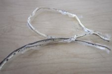
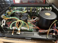
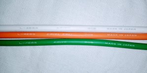
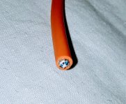
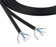
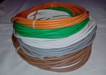
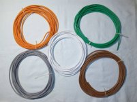
For Sale Canare L-4E6S raw pro audio cable, 24AWG, 4 cond, 6mm, 97m
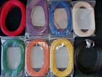
Up for sale set of luxury raw mic cable from Canare, quad-type, with 4 conductors! instead 2, what allow to supress typical noises greater, and keep highs pristine.
Also cool to wire studio devices, mics, drumsets/orchestras, etc.
Rare offer: colorful set just at once, with no long previous ordering & waiting when you order from dealers.
5 colors 10-12m each, ~55.28m total.
Manufacturer site : https://www.canare.com/analogaudiocable
Type : L-4E6S
Dia: 6mm
Wires dia: 24AWG
Price lowered from -$250,-
Now: 55.28m - $210,-
FREE shipping across EU/UK.
Items will be packed carefully with international tracking across all distance.
---
Also for sale other items, some presented here, small items can be added into box:
Also cool to wire studio devices, mics, drumsets/orchestras, etc.
Rare offer: colorful set just at once, with no long previous ordering & waiting when you order from dealers.
5 colors 10-12m each, ~55.28m total.
Manufacturer site : https://www.canare.com/analogaudiocable
Type : L-4E6S
Dia: 6mm
Wires dia: 24AWG
- brown
- grey
- white
- amber
- green
Price lowered from -$250,-
Now: 55.28m - $210,-
FREE shipping across EU/UK.
Items will be packed carefully with international tracking across all distance.
---
Also for sale other items, some presented here, small items can be added into box:
- Grayhill 2, 3, 4 decks, single shaft rotary switches, up to 2x6, 1x12 poles
- Mogami W2944 pro audio cable, 2.5mm, 8 colors, ~235m
- high voltage mica caps, 1000-5000V, Airvox, Sangamo, Sprague
- Triplet ultra rare 4.5 inch VU meter
- different Marion meters, 2 and 3 inch
- Triplet mains distributor for USA plug, 120V, 10 sockets
Attachments
-
 Копия IMG_20230309_070828~3.jpg421.5 KB · Views: 185
 -
 IMG_20230309_071129~4.jpg678.9 KB · Views: 192
 -
 Canare L4E6S.png154.6 KB · Views: 200
 -
 Снимок экрана 2022-04-29 в 07.08.38.png170.8 KB · Views: 189
 -
 FAB25EED-07C3-4A3A-8949-F4A0A5FAAD8E.jpeg41.4 KB · Views: 172
 -
 CC089469-C141-4DE7-81FD-7FFCA29E2B99.jpeg43.1 KB · Views: 167
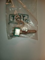
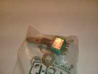
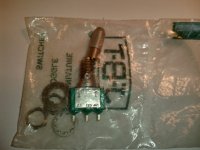
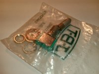
For Sale JBT toggle switches, NAIS, Takamisawa, Noble, Carling, Neutrik XLR Parts
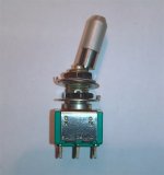
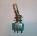
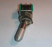
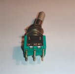
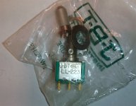
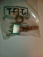
Up for sale set with 10 pcs (min quant in any combinations) luxury JBT toggle switches (USA made), never used :
One of most attracting features - shaft locking, with prevention sudden toggling.
I.e. you need pull shaft to toggle shaft from position to position.
Other feature, aluminium head of shaft can be unscrewed off and anodized, or painted/varnished into desirable colors.
All time kept in soldered original manufacturer plastic bags in normal stable store temperature.
Price - $79,-USD, FREE shipping across EU/UK.
PayPal payment way is possible with some specific.
Items will be packed carefully, supplying from Ukraine with all distance tracking.
Items also can be bought how mix sets in any combination with listed above, or with some other my items, see below ⤵️
starting from total $80,-.
Also possible for sale, can be put into common box to optimize shipping:
- LL123 - single row contacts, two positions
- LL223 - dual row contacts, two positions
- LL232 - dual row contacts, three positions, attention pls, type ON - ON - ON between rows
One of most attracting features - shaft locking, with prevention sudden toggling.
I.e. you need pull shaft to toggle shaft from position to position.
Other feature, aluminium head of shaft can be unscrewed off and anodized, or painted/varnished into desirable colors.
All time kept in soldered original manufacturer plastic bags in normal stable store temperature.
Price - $79,-USD, FREE shipping across EU/UK.
PayPal payment way is possible with some specific.
Items will be packed carefully, supplying from Ukraine with all distance tracking.
Items also can be bought how mix sets in any combination with listed above, or with some other my items, see below ⤵️
starting from total $80,-.
Also possible for sale, can be put into common box to optimize shipping:
- Grayhill 2, 3, 4 decks, single shaft rotary switches, up to 2x6, 1x12 poles
- Mogami W2944 pro audio cable, 2.5mm, 8 colors, ~236m
- Canare L-4ES6 pro mic cable, Japan, 4 wires instead 2 to supress all noises, uniq offer - 9 colors
- high voltage mica caps, 1000-5000V, Airvox, Sangamo, Sprague
- Triplet model 426 ultra rare 4.5 inch VU meter
- different Marion meters, 2 and 3 inch
- Tripplite mains distributor for USA plug, 120V, 10 sockets
Attachments
-
 JBT lat 1.jpg101.9 KB · Views: 242
 -
 JBT lat 2.jpg115.9 KB · Views: 251
 -
 JBT front.jpg77 KB · Views: 244
 -
 JBT rear.jpg91.7 KB · Views: 244
 -
 JBT USA bag.jpg233.1 KB · Views: 225
 -
 IMG_20221121_231654.jpg197.7 KB · Views: 229
 -
 IMG_20221121_231807.jpg180.9 KB · Views: 218
 -
 IMG_20221121_231911.jpg151.2 KB · Views: 206
 -
 IMG_20221121_232028.jpg249.2 KB · Views: 216
 -
 IMG_20221121_232048.jpg217.9 KB · Views: 208
 -
 IMG_20221121_232345.jpg259.1 KB · Views: 231
For Sale Pro audio cable Mogami W2944
Up for sale pro audio cable set Mogami W2944, Japan, dia 2.5mm, balanced or stereo.
Manufacturer site : https://mogamicable.com/category/bulk/console/
8 colors, ~29-31m each color/232m - $325,-.
Item will be packed carefully with international tracking across all distance.
FREE shipping across EU/UK.
---
See also my other items (some presented here on SwapMeet), small items can be added into box:
- Grayhill 2, 3, 4 decks, single shaft rotary switches, up to 2x6, 1x12 poles
- Canare L-4ES6 pro mic cable, Japan, 4 wires instead 2 to supress all noises, uniq offer - 9 colors
- high voltage mica caps, 1000-5000V, Airvox, Sangamo, Sprague
- Triplet ultra rare 4.5 inch VU meter
- different Marion meters, 2 and 3 inch
- mains distiributor Tripplite, rack 19 inch, for USA 120V plugs
Attachments

Where put volume control Elektor Discrete preamp 1994
- By Tailgunner
- Solid State
- 10 Replies
This pre-amplifier was published in 1994 in Elektor.
https://drive.google.com/file/d/1gFx9xPYtoKBOYfyoPnygX1_ZdWmwhsKf/view
Problem is that I don't see the volume control for it.
I know it's a noob question but where to put it and what value should it be?
https://drive.google.com/file/d/1gFx9xPYtoKBOYfyoPnygX1_ZdWmwhsKf/view
Problem is that I don't see the volume control for it.
I know it's a noob question but where to put it and what value should it be?
Long time lurker, finally stepping out of the shadows!
- By Rad-Cap
- Introductions
- 2 Replies
Hello looking forward to helping out wherever I can and understand things better 😊
Bugera BVP5500
- By Carlosraj
- Solid State
- 0 Replies
Hi
Does anyone has the schematic for the above amp?.
Thanks
Does anyone has the schematic for the above amp?.
Thanks
Tube amp journey
- By Tony_M
- Introductions
- 1 Replies
I've built a few Marshall style amps and always looking for that "sound" albeit it's subjective.
Always looking to learn how to improve my knowledge and skill set for building.
Always looking to learn how to improve my knowledge and skill set for building.
Soundstream TXP1.12000D
Hi all,
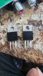
Can anybody tell me if those rectifiers are same with anode in centre pin.
One rectifier is connected to positive pin of two capacitors and same capacitors ground is connected to primary ground terminal.
second rectifier is connected to secondary ground of transformer.
Can anybody tell me if those rectifiers are same with anode in centre pin.
One rectifier is connected to positive pin of two capacitors and same capacitors ground is connected to primary ground terminal.
second rectifier is connected to secondary ground of transformer.
Attachments
Thread used for feet ESL57
- By AdVis
- Planars & Exotics
- 10 Replies
I've unscrewed the feet of my ESL57's so they can sit comfortably on top of my DIY Ripoles and they do sit there comfortably but I would like to have it all a little bit more secure. It seems quite feasible to bolt them to the Ripoles. And it seems like a good idea to use the thread already there for the rear foot.
Except, I can't seem to find what kind of thread it is! Because I am pretty sure it is an English thread, which is rare over here.
Can anyone tell me what thread I should use for a bolt that fits in place of the rear foot of an ESL57?
Thanks in advance!
Ad
Except, I can't seem to find what kind of thread it is! Because I am pretty sure it is an English thread, which is rare over here.
Can anyone tell me what thread I should use for a bolt that fits in place of the rear foot of an ESL57?
Thanks in advance!
Ad
Pentode loadlines
- By rogerayotte
- Tubes / Valves
- 8 Replies
I am quite a novice, but I do understand the nature of graphically drawing a load line for a triode. I have yet to find a good explanation and illustrations of pentode load lines.
Any points to good basic explanation?
Roger
Any points to good basic explanation?
Roger
Maximum anode dissipation of UX-210 Tube
- By toshiba_nz
- Tubes / Valves
- 1 Replies
I had a quick look at the RCA type 10 datasheet which didn't list maximum anode dissipation, although the picture in the datasheet showed a globe shape (which may have different specs to a shoulder ST shape short plate type 10?)
Does anyone know the maximum anode dissipation of a UX-210 globe tube (long plate)
Does anyone know the maximum anode dissipation of a UX-210 globe tube (long plate)
Can I obtain the best phase response without measurement?
Can I obtain the best phase response without performing measurements? If so, how to achieve it?
Also, how did the speaker manufacturers in the 70s and 80s (pre-1985) manipulate the phase response at that moment?
Also, how did the speaker manufacturers in the 70s and 80s (pre-1985) manipulate the phase response at that moment?
Toroidal Tansformer Aleph JZM Australia
- By Andy999
- Power Supplies
- 10 Replies
Hello,
I'm looking for toroidal transformer supplier in Australia for my Aleph JZM, so 300VA 18V secondaries. I read about having high quality secondary windings and am looking for advice from those who may have had experience with Australian suppliers. I'm rural and don't have a supplier close by so trying to make the best choices before the build.
So for I have a choice between
-VIGORTRONIX from Element14 with daul primaries to select between 115v and 230v AC https://au.element14.com/vigortronix/vtx-146-300-218/300va-toroidal-transformer-2x18v/dp/281770002
-TorTech, Australian manufacturer, single Primary https://www.tortech.com.au/product/toroidal-ei-transformer/toroidal-transformer/
-PowerTran from Altronics, the most pricy, singel primary. https://www.altronics.com.au/p/m5518c-powertran-18-18-300va-toroidal-transformer/
Any perspectives, would be appreciated.
The total-sum Sound Quality of Phone music aps + Bluetooth
- By Audio>X
- Digital Source
- 2 Replies
Hi there folks,
I am a 'funny old fart' that doesn't own or use a Smart Phone, but I am interested to know about the sound quality people are getting
using Phone music aps + the use of Bluetooth ???
EG. Are there differences between Spotify, iTunes and YouTube?
Hopefully some people can enlighten me 🙂
I am a 'funny old fart' that doesn't own or use a Smart Phone, but I am interested to know about the sound quality people are getting
using Phone music aps + the use of Bluetooth ???
EG. Are there differences between Spotify, iTunes and YouTube?
Hopefully some people can enlighten me 🙂
WTB Crown IC150A Volume Knob
Hi
Would anyone have a volume knob for a Crown IC150a preamp? Ive been looking for one in my house and ebay for years


Thanks!!
Would anyone have a volume knob for a Crown IC150a preamp? Ive been looking for one in my house and ebay for years
Thanks!!
JBL LX44 Midrange replace
Hello
Im new to this so let me know if this is the wrong place to ask this question, thanks
JBL LX44 Midrange drive code - 405G, 5 inch external diameter, Polymer laminate cone, 8 ohm
I have a very old pair of JBL LX44 speakers and its time to change out the mid range drivers, Im not replacing the speakers as I still love them.
I have looked on the net for new ones but can only find refurbed models and would prefer to replace them with new 405G's or a different brands better alternative. I also cant find anywhere the specs of the 405G's - Frequency Response, Power Handling (max), Sensitivity etc.
Can anyone advise where I might be able to buy new 405G's or a different brand or particular speaker driver that would be a great replacement OR does anyone know the specs of the JBL 405G drivers so I can go looking for a replacement.
Thank you in advance and look forward to any help you may be able to offer
cheers
Terry
MEH to Replace Mid Tops
Hello,
Last Summer I currently built the following stack.
Mid Top - selenium Pas3Ma1 - x2 HP 326HZ
Kicks - Cubo Kick - x2 HP 120HZ LP 210 HZ
Subs - MHB 46x2 HP 30/40HZ LP 80 HZ
I am looking to replace my Mid Top With a MEH Synergy Horn Type. This Horn will basically remove the needs for my kicks. But I want to keep them.
should I just keep the kicks and double up in that 150-250hz range? Or should I try and structure the MEH with a HP around 300HZ and then the Crossover in the MEH to be higher around the 800/850 Range. I would not have ports if I go with option #2.
from reading If I get rid of the 150-250hz range in the MEH, then the horn does not get any loading? (Is this true?) and the MEH design becomes pointless.
Thoughts?
Thanks,
Cole
Anyone tried or heard the Teramps and/or Monacor full range offerings?
- By CPTX
- Full Range
- 11 Replies
Currently shopping the 8" full range market......found these.....specs and FR are encouraging for OB/sealed and both appear easy to drive.
Found some info here and other locations regarding the Monacor; but not much regarding Teramps (I suspect they have more of a car audio following)
First the Teramps....then the Monacor


Found some info here and other locations regarding the Monacor; but not much regarding Teramps (I suspect they have more of a car audio following)
First the Teramps....then the Monacor
Correct driver positioning/mounting for TS parameters measurement
- By guferr
- Subwoofers
- 5 Replies
Most setups I've seen for measuring TS parameters of a driver, independently of the electronics used for the measurement, have been placing a driver with its cone firing up and its magnet sitting flat on a surface like a desk, usually with some absorbing material like a rubber below.
My question is: Does this make sense according to the assumptions used in the derivation of the TS parameters?
To begin with the driver is literally above an obstacle, the surface above which its laying.
If that surface were the floor, this would basically be laying on an a large sound-reflecting plane. It's going to be interacting directly with it.
And often I've seen the driver sitting near to an edge of the desk or bench, so it's not even close to an infinite plane.
I originally figured that hanging a driver in the middle of the room could be a good idea, until I remembered this allows its own body to move too, so it becomes more of a system like two asymmetrical masses coupled by a single spring, rather than a single mass coupled by a spring to a fixed point.
I tested this by simply firmly holding the speaker near Fs while hanging, and it did change its behavior, while simply approaching my hand didn't.
And this is still different from having something like a steel arm holding it, because my hand is very damping, it's damping the vibrations and not actually forcing its body to be fixed.
Same thought goes for a speaker over something like a damping rubber versus a speaker held by a vise on a bench, they'll be different.
Maybe the influence of those different fixation methods isn't that large, but I suppose that having the speaker over a large surface (like above the floor) or close to an edge of a large surface (like in the edge of a desk) makes a reasonable difference.
Which is the proper way to fix it?
Not technically a Pass Labs product, but need GFP-750 help
- By Dougey Jones
- Pass Labs
- 41 Replies
@Nelson Pass
I own a beautifully kept Adcom GFP-750 (blue PCB) that is the backbone of my stereo system and has been for many years. It's developed a problem lately and I'm not sure what to do about it. When I use the remote to adjust the volume up or down, sometimes it "sticks" and the motor runs the volume ALL the way up or ALL the way down, and it keeps going in that direction until I physically stand up and go stop the knob from trying to go in whatever direction it's going.
Any ideas on what part(s) need to be replaced or repaired to stop this? Everything else works great.
Thanks!
A a marvelous jig for cutting splines
- By BillEpstein
- Construction Tips
- 16 Replies
I've done my amplifiers with wood cases forever and always with mitered corners. In all that time, even knowing that a mitered glue joint is inherently weak due to being end grain to end grain, never had a failure. Until now. I sent this 6BQ5 amp off to a friend who returned it as carefully packed as UPS did on the outgoing trip but nevertheless,

I couldn't effect a really invisible repair so, never needing an excuse to do some more woodworking, I started over.
This time I wouldn't shy away from the splines I should have always used but was afraid to try. I wanted something more than just a panel with a pair of 45s to make the cuts on my contractor saw and came across this: https://kmtools.com/blogs/news/miter-splines?_pos=1&_sid=ffc1adf4d&_ss=r Most of what I've seen from him always seemed overly complicated and time consuming but this jig turned ot to be perfect; simple to make and very secure. Perfect for my 77 year old shaky hands.

The box rode the fence without a wobble and the sandpaper I added turned out to be unnecessary.
The result with ebony splines in the cherry I think looks pretty good. Oh yeah, I added long grain to long grain suspender battens to the belts, the splines, just in case.

Once the shellac cures enough to wax with 4 aught, it should look even better than the original.
I couldn't effect a really invisible repair so, never needing an excuse to do some more woodworking, I started over.
This time I wouldn't shy away from the splines I should have always used but was afraid to try. I wanted something more than just a panel with a pair of 45s to make the cuts on my contractor saw and came across this: https://kmtools.com/blogs/news/miter-splines?_pos=1&_sid=ffc1adf4d&_ss=r Most of what I've seen from him always seemed overly complicated and time consuming but this jig turned ot to be perfect; simple to make and very secure. Perfect for my 77 year old shaky hands.
The box rode the fence without a wobble and the sandpaper I added turned out to be unnecessary.
The result with ebony splines in the cherry I think looks pretty good. Oh yeah, I added long grain to long grain suspender battens to the belts, the splines, just in case.
Once the shellac cures enough to wax with 4 aught, it should look even better than the original.
service manual or schematic for Telefunken TR-1500 or Project One Mark 1500 PLEASE
- By JackB1972
- Solid State
- 8 Replies
I have Project One Mark 1500, Looks to be exact copy of Telefunken TR-1500. I am in bad need of schematic or service manual... Thank you


-
Locked
For Sale 3e Audio TPA3251 & PSU 200W 36V 6A
Hi Guys - I have a lot of 3e Audio stuff that I bought and have done nothing with. Just want to move it on to someone who will make the project and appreciate it.
This is my first time and I hope it is OK.
Starting with:
AMP Balanced/unbalanced AUD85.00
PSU AUD75.00
Plus postage to where ever you are.
PayPal (family and friends.
Thanks
Dan
This is my first time and I hope it is OK.
Starting with:
AMP Balanced/unbalanced AUD85.00
PSU AUD75.00
Plus postage to where ever you are.
PayPal (family and friends.
Thanks
Dan
Attachments


-
Locked
For Sale Amp TPA3255 and PSU Never used - eAudio (previously not clear - I think)
Hi Guys - I have a lot of 3e Audio stuff that I bought and have done nothing with. Just want to move it on to someone who will make the project and appreciate it.
This is my first time and I hope it is OK.
Starting with:
TPA3255 AMP Balanced/unbalanced AUD85.00
PSU AUD75.00
Plus postage to where ever you are.
PayPal (family and friends.
Great value as the price is in Aussie Dollars - these are the cheap compared with other currencies.
Thanks
Dan
This is my first time and I hope it is OK.
Starting with:
TPA3255 AMP Balanced/unbalanced AUD85.00
PSU AUD75.00
Plus postage to where ever you are.
PayPal (family and friends.
Great value as the price is in Aussie Dollars - these are the cheap compared with other currencies.
Thanks
Dan
Attachments
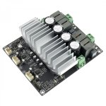
Hi All!
- By dptucunduva
- Introductions
- 1 Replies
Hello everybody!
My name is Daniel, and although I had my share of simple speaker builds, with low quality drivers and quite basic and unexpensive crossovers, I do not have that much experience.
This time I am going for a little more complex project, which I want to share with you guys - and get a few insights too, of course!
See ya!
Introduction
- Introductions
- 2 Replies
Hello!
My name is Don, and I am an amp-oholic. I am here to learn more about amplifier circuitry and repair/modification, as well as just being a part of a community of like-minded audiophiles. Thanks!
My name is Don, and I am an amp-oholic. I am here to learn more about amplifier circuitry and repair/modification, as well as just being a part of a community of like-minded audiophiles. Thanks!
Introduction/ hello
- By Nick Birkby
- Introductions
- 2 Replies
Hi all,
Im a musican and home studio enthusiast from Cape Town, South Africa. I have a fairly wide collection of analog outboard studio gear, some of which I have done minor repairs to. Im interested in possibly building an SSL bus compressor clone at some point in the future but at the moment I really just need an occasional bit of advice on repairs or components.
Cheers, Nick
need schematic Cary CAD 211M Anniversary Edition
- By brucebosler
- Tubes / Valves
- 7 Replies
contacted Cary and they sent a few sketches that are very incomplete
Attachments
best tweeter for "silky" highs?
- By Ghoostknight
- Multi-Way
- 152 Replies
Hello
im planning to build a speaker, but on my current presonus eris e8 with silk dome tweeter i kinda hate the highs, they never sound right, they sound different with different cables/dacs but im still unhappy
what is in your opinion the tweeter "topology" (AMT, planar, ribbon, electrostatic, soft dome, hard dome horn etc..) that sounds the best/smoothest or "most silky" in terms of smoothness but still representing the original signal faithfully?
im also specially curious what you guys think of full range driver in comparison to tweeters ?
Pabst Motor
- By findog3103
- Power Supplies
- 3 Replies
I have an older Brinkmann Balance Turntable that uses a Pabst motor for its belt drive. It is having trouble holding speed at 33.33 rpm from one day to the next. For example, yesterday the speed was spot-on. Last night, I turned it off. Today, I turned it on, waited for about 45 minutes and the speed was 33.11. Nothing else changed from last night: the placement, my electric. The speed at 45 rpm is fine each day. I use a RöNt that was serviced at Brinkmann last year and the bearing was serviced as well this year. I had the motor serviced a couple years back, but when I ask the person who serviced it, he said check with Brinkmann. Has anyone else had experience with Pabst motors and these issues?
Thanks.
Thanks.
TI power stage for selfoscillating amplifier
- By Sous
- Vendor's Bazaar
- 43 Replies
Class D half-bridge amplifiers as we known to have some disadvantages. The main one is the requirement for a power supply. As a consequence of the pamping effect Hi-quality bipolar SMPS almost not available on the market, especially if you need to get a small power.
We have designed a circuit to adapt the Texas Instruments bridge power stages for use in a self-oscillating amplifier circuit. In such a case, a single monopolar voltage is sufficient.
TAS53xx, TAS51xx type chips are well suited for self-oscillating operation: they provide linearity in the of 0.2% without any special means. Propagation delay of 50-60ns contributes to the improvement of dynamic characteristics.
Even for a UcD modulator, this makes it possible to get better than 0.001% THD+noise at first watts without loss of quality at high frequencies.
Considering further of the technology, modern modulators like ncore/purifi can be easily applied to this platform. In this case the THD+noise will be below 0.001% in the whole frequency and power range.
We have made a variety of prototypes with different variations of the bi-polar supply for the modulators.
As is often the case, the most primitive one turned out to be the most effective as well.
As a result, a virtual ground source and a level shifter added.
The prototype is built on TAS5342 in PBTL mode.The block diagram of the amplifier is shown below:
Due to the peculiarities of the output stage, the amplifier cannot clipping, it simply disconnects the half-wave of the signal. but this is not a bug, but a feature 😉
![20231230_203747[1].jpg](https://www.diyaudio.com/community/data/attachments/1172/1172776-32c28ebbbc6088b37a63e2bd523762e6.jpg?hash=MsKOu7xgiL "20231230_203747[1].jpg")
Tipical performans ( modern modulator like purifi et400)
15W 4ohm real speaker, we can't measure better because our DAC/ADC is of insufficient resolution

We tried our best and fit everything into a two-layer PCB. PP capacitors panasonic are used on the output. 8x470µf panasonic FR are installed in the power main, 2x220µf panasonic FM in the supply of the analog part. OA OPA1602+ high-speed comparator TL3016 are used in the modulator, preamplifier is assembled on OPA1612.
Subjectively it turned out to be quite pleasant sounding.
The module supports 2ohm load.
The signal spectrum in the picture is obtained with the power supply for 9 dollars, 24V 6A of the lowest quality.
We have designed a circuit to adapt the Texas Instruments bridge power stages for use in a self-oscillating amplifier circuit. In such a case, a single monopolar voltage is sufficient.
TAS53xx, TAS51xx type chips are well suited for self-oscillating operation: they provide linearity in the of 0.2% without any special means. Propagation delay of 50-60ns contributes to the improvement of dynamic characteristics.
Even for a UcD modulator, this makes it possible to get better than 0.001% THD+noise at first watts without loss of quality at high frequencies.
Considering further of the technology, modern modulators like ncore/purifi can be easily applied to this platform. In this case the THD+noise will be below 0.001% in the whole frequency and power range.
We have made a variety of prototypes with different variations of the bi-polar supply for the modulators.
As is often the case, the most primitive one turned out to be the most effective as well.
As a result, a virtual ground source and a level shifter added.
The prototype is built on TAS5342 in PBTL mode.The block diagram of the amplifier is shown below:
Due to the peculiarities of the output stage, the amplifier cannot clipping, it simply disconnects the half-wave of the signal. but this is not a bug, but a feature 😉
Tipical performans ( modern modulator like purifi et400)
15W 4ohm real speaker, we can't measure better because our DAC/ADC is of insufficient resolution
We tried our best and fit everything into a two-layer PCB. PP capacitors panasonic are used on the output. 8x470µf panasonic FR are installed in the power main, 2x220µf panasonic FM in the supply of the analog part. OA OPA1602+ high-speed comparator TL3016 are used in the modulator, preamplifier is assembled on OPA1612.
Subjectively it turned out to be quite pleasant sounding.
The module supports 2ohm load.
The signal spectrum in the picture is obtained with the power supply for 9 dollars, 24V 6A of the lowest quality.
Attachments
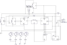
![20231230_204231[1].jpg](/community/data/attachments/1172/1172777-a375a4acf93023c4ec1063e406b4e3b5.jpg?hash=o3WkrPkwI8)
sound card test
- By arivel
- Equipment & Tools
- 44 Replies
HI .
Do you know possibly free software that checks the hardware functionality of the USB sound card with a test?
Do you know possibly free software that checks the hardware functionality of the USB sound card with a test?
Port tube resonace?
- By Booger weldz
- Subwoofers
- 5 Replies
That’s a ‘54cm port tube resonance (halfwave) not a 81 cm/3, 1/4 wave resonance , right?
(320 hz in the response shape)
(320 hz in the response shape)
Attachments
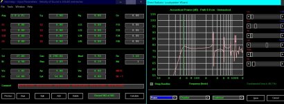
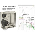
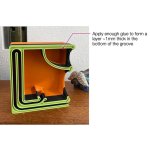
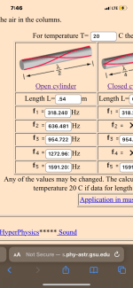
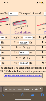
Free version of CrossLite+?
- By eriksquires
- Software Tools
- 5 Replies
Recently I saw a demo of CrossLite+ a tool to develop DSP filters. I was hoping I could ask for a free equivalent besides REW. I've looked at REW and it seems to do everything completely backwards from what I expect, and very much tied to specific DSP platforms.
I want something that lets me draw a couple of filters and examine how the filters behave in terms of phase and time. For instance, have 2 "ideal" drivers, put them through an arbitrary LP and HP filter and see what this means to the impulse, phase and group delay. I'm afraid all the wordy explanations I read are not sticking with me, so I'm hoping for something interactive with graphs that let me feel the changes.
Thank you,
Erik
Are the lines supposed to look like this?
Hello!
First speaker attempt - narrow and tall to flank tv and replace soundbar.
Is my crossover design in VituixCad heading in the right direction? (Should the graph look like that?)
If yes, then I'm going to start hunting for or producing with a mic the .frd file for the HiVi M6N 6" because I like the way the HiVi aluminum/magnesium cones look.
Drivers:
Tweeter: Dayton DC25T-8
Mid: HiVi (Swan) M4N 4"
Woofer: Dayton GF180-8 6.5"
Thanks for any input!
TEAC UD-501 DAC ~ PCM/DSD/USB ~ Dual Mono with Headphone Amplifier
- By bigskyaudio
- Swap Meet
- 1 Replies
New in open factory box TEAC UD-501 DAC with headphone amplifier. USA model in silver color. I am the original purchaser and this item has never been used in any way nor powered up. Sold "as-is" and no warranty is expressed or implied. No returns or refunds. Sells and ships to USA residents only. $400 plus shipping.

For Sale SONY DAS-R1 DAC Digital To Analog Converter Japan 100V
- By bigskyaudio
- Swap Meet
- 2 Replies
SONY DAS-R1 digital-to-analog converter in very good cosmetic condition and working well. Features twin Philips TDA1541 DAC chips in an overlapping staggered configuration operating in 18-bit with 8x oversampling at 352.8 kHz. It has 2 coaxial SPDIF inputs along with a proprietary twin optical input for the CDP-R1 CD player (not included). $1500 plus actual shipping & insurance cost.
This DAC is approx 37 years old and may require some service in the future as it is vintage equipment! I purchased it second hand from an audio store in Japan many years ago and it is a Japanese domestic market item operating on 100 Volts AC. A 120V to 100V AC step down transformer is recommended.
Sold "as-is" and no warranty is expressed or implied. No returns or refunds. Sells and ships to USA residents only. No APO/FPO addresses. Shipping and insurance may be high because of an oversized box weighing 42 pounds. PayPal use will include a transaction fee. Please pm if interested.
Attachments
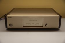
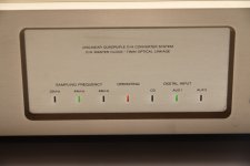
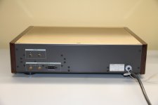
WTB IanCanada's FiFoPiMa Board
Please PM if you have an available, used FiFoPiMa board you're willing to part with.
Rick
Rick
Hello
- By primary100
- Introductions
- 1 Replies
Hi
I have been involved in the recording and audio industry for many years - hi fi reviewing alongside studio work (currently for mix engineer Spike Stent) and consultancy for some hi fi manufacturers. Ever since building valve amps with my father from an early age I've never been to far away from building speakers and amps, mostly for fun, although sometimes they have ended up being used in the studio. The process of experimenting then building, measuring and tuning a speaker project is something I still find endlessly fascinating and very rewarding, especially when it goes right -
I have been involved in the recording and audio industry for many years - hi fi reviewing alongside studio work (currently for mix engineer Spike Stent) and consultancy for some hi fi manufacturers. Ever since building valve amps with my father from an early age I've never been to far away from building speakers and amps, mostly for fun, although sometimes they have ended up being used in the studio. The process of experimenting then building, measuring and tuning a speaker project is something I still find endlessly fascinating and very rewarding, especially when it goes right -
Bridged amp question
I have a Memphis 400.4 six five series bridged to focal k2 es 165k in front. 1 and 2 to left 3 and 4 to right . Useing the passive crossovers. Question how can put the tweeters on say 1 and 2 and midbass on 3 and 4. With crossovers given with focals .
Duncan amps tube pages down
- Tubes / Valves
- 9 Replies
Duncan amps tube pages are down, I get this - MySQL connect failed: No such file or directory - I hope it's not Psud all over again.
Andy.
Andy.
What do you think about this Chinese audio processor? Is it any good? LA-480
- By latoresp
- PA Systems
- 28 Replies
Honestly, I don't have enough knowledge to determine whether it's worth it or not, but what I do know is that when vendors add chip models to the specifications it's a good sign 🤣🤣
4in 8out about 185€ inclued shiping to EU (+import taxes) on alibaba
340€ on aliexpress all inclued..
What do you think?
4in 8out about 185€ inclued shiping to EU (+import taxes) on alibaba
340€ on aliexpress all inclued..
What do you think?
Attachments
For Sale GainWire MK3 lay 1.6 + SSR protect (PCB only)
I have 4 free PCB sets for GainWire MK3. This is an excellent preamp/headphone amp, a must try, highly recommended!
Original thread: https://www.diyaudio.com/community/...re-phone-amp-with-very-low-distortion.296545/
GainWire MK3 + SSR3 pcb (30 eur + shipping)
I send by post all over the world. Paymet via PayPal (F&F)
Original thread: https://www.diyaudio.com/community/...re-phone-amp-with-very-low-distortion.296545/
GainWire MK3 + SSR3 pcb (30 eur + shipping)
I send by post all over the world. Paymet via PayPal (F&F)
Attachments

Introduction
- By Gafabo
- Introductions
- 1 Replies
Hello from Hungary! I'm gafabo.
Welcome to the diyAudio community!
I've been reading interesting topics here for a couple of years. Thanks for the inspiring posts! Maybe it's time for me to speak up. When I was university student, I already built myself an amplifier and a DAC, after which there was a big break. Now I started thinking about building another old style DAC. In addition, I would be very interested in an SE tube amplifier, which has interested me for a long time. Just have enough free time!
Sandy - Power VFA
- Solid State
- 41 Replies
Final Steps - Projects!!
VFA P FET 1-1-3.4 V3.3
VFA P FET 1-1-3.4 V3.3
Attachments
-
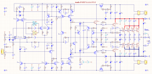 Audio P FET 1-1-3.4 V3.3 Sch.png154.9 KB · Views: 2,783
 -
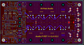 Audio P FET 1-1-3.4 V3.3 Pcb.png486 KB · Views: 942
 -
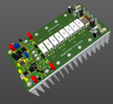 Audio P FET 1-1-3.4 V3.3 3D.png279.7 KB · Views: 943
 -
P FET 1-1-3.4 V3.3 3D.pdf7.6 MB · Views: 324
-
P FET 1-1-3.4 V3.3.PDF1.6 MB · Views: 452
-
P FET 1-1-3.4 V3.3.zip6.7 MB · Views: 264
-
Project Outputs for P FET 1-1-3.4 V3.3.zip899.6 KB · Views: 214
just diy car audio
- By proland
- Introductions
- 2 Replies
Hi my name is Paul I am trying mainly to understand how audio works in general to setup my car audio system, nothing fancy but aiming SQ in general
JBL 2268HPL vented alignments
I've decided to build a pair of subs for my son's studio, likely using a pair of 18" JBL 2268HPL drivers. The goal is low THD in vented or aperiodic enclosures, to determine the best design for crossover points higher than most typical larger subs can pull off for their size.
At first we looked at dual 12s, but none of the decent reasonably priced 12s were capable of the low distortion figures the JBLs could do from way down low to way past 100hz. The SB34NRXL is the only 12 I've used with distortion numbers closer to the JBL ($400), but one of them is close to the cost of the JBL ($340). That means closer to $700 using 2 of the SBs, for the same cone surface area as the JBL. The SBs have the xmax advantage over the JBL 2268s, but that isn't relevant at higher frequencies closer to the LP cutoff.
I've heard the JBLs in various configurations and enclosures. They are likely the best 18s available under $500 for vented enclosures and open baffle based on my listening experiences. Because of this, my son has gotten ahold of a pair of the JBLs and wanted to build a pair of vented subs, but he's also open to aperiodic enclosures if they can go down into the mid 30s using little to none shelf correction.
We'll be running these off of 1000W Icepower plate amps with very light EQ, one driver per enclosure, per side. They'll mainly be used for mixing electronic pop, jazz and acoustic music. He plays drums and is very picky about low end. The bass has to be accurate and have exceptional dynamic capabilities.
I preferred the 2268s because they have an excellent reputation and sound great in the right enclosure at just about any level. This is another trait not typical with large pro audio drivers. We looked at 18 sound, B&C and Eminence, but the JBL always won due to price vs performance.
The enclosures were going to be 6 - 7 cu ft based on the preliminary specs I have on the 2268s. I'd like to hear about some of the designs others have done using JBL2268s.
Capacitor Recommendation For Recapping Cheap Bookshelf Speakers
Hello everyone,
I have a pair of older Pioneer bookshelf speakers. They were probably never that great sounding, but I think they sound a little dull at the moment. They do not have a crossover, just a single electrolytic in series in between the driver and the tweeter. Can you please recommend a capacitor that is at max 10$ for one, that would bring a new life to them? I have heard a lot of praise for the film capacitors, would they be a good choice? Should the value remain the same (2.7uF)?
Thank you
Attachments
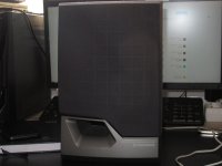
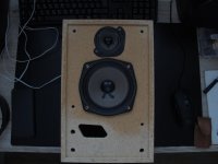
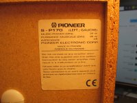
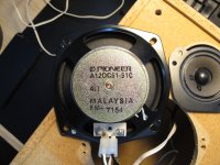
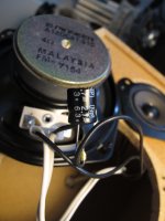
For Sale Denon DL-103SL
I purchased this and then was gifted a Denon DL-103FL
DENON DL-103SL Special Ceramic Moving Coil Turntable AT-MS11 Headshell $375 firm
This is a special cartridge. It was produced in 1989 with a white ceramic body for a more rigid body and faster response. It takes the already great sound of the legendary DL-103SL and takes it to the extreme. It also uses a 99.9999% high purity copper wire to reduce distortion.

Thanks for looking.
DENON DL-103SL Special Ceramic Moving Coil Turntable AT-MS11 Headshell $375 firm
This is a special cartridge. It was produced in 1989 with a white ceramic body for a more rigid body and faster response. It takes the already great sound of the legendary DL-103SL and takes it to the extreme. It also uses a 99.9999% high purity copper wire to reduce distortion.
Thanks for looking.
New Member
- By taddy
- Introductions
- 1 Replies
Hi everyone,
I'm Tom from the UK. I enjoy fixing music related electronic equipment, especially guitar valve amplifiers. I have some experience in this area but am in no way an expert so will probably be firing a whole load of questions to y'all over the next few years!
I'm Tom from the UK. I enjoy fixing music related electronic equipment, especially guitar valve amplifiers. I have some experience in this area but am in no way an expert so will probably be firing a whole load of questions to y'all over the next few years!
DIY-ish replacement for my Z-5500 Desktop system?
Hi all, sorry if this is a little redundant...
I've had a Logitech Z-5500 for like 15 years now on my various Desktop PCs. I've been super happy with it overall, but we've had a wild ride together. Several years ago, I replaced the main L/R speakers with 2 small bookshelf-size that I built with help from the kind folks here, using 3" MarkAudio drivers. They sound great. The rest of the system is stock.
Recently, I've started hearing some pops and crackles (almost a sizzling static) from all speakers when there's no other output. I'm afraid the amp, or some other internal component, is finally about to let out the magic smoke.
I would like to begin investigating options for replacement. My current PC (just built), has a Creative Sound Blaster AE-5 Plus sound card, so I'm working with 3x analog outputs that need to be accepted by whatever sound system I buy/build. I'd like to use my current main speakers, and I have 2 Definitive Tech surrounds that might make good rear or center speaker(s). Beyond that, I'm looking to buy/build whatever I need. I'm not interested in going the full AVR route. I've tried that once before, and not only do I not really have the room for it, I never got the inputs and outputs to work correctly with Windows. Also, I've heard about routing sound through HDMI via my video card, but that doesn't appeal either, since it involves a 'phantom monitor', which invokes all sorts of additional issues.
I thought about something like the Aiyima A09, but the one actual review I found of it wasn't encouraging.
As for the Sub, I would probably go with a Polk PSW10, unless you folks have a better suggestion in the same general price range. I've installed 2 of those in homes for friends, and they are solid units with good sound for the price, in my 'very much not a professional' opinion.
Bottom line: I'm looking for something that will sound as good or better than the Z-5500, doesn't take a degree in electrical engineering to set up, and won't totally break the bank. I'm not 100% fixated on 5.1, either. If there's such as thing as 3.1 (L/R/C/Sub), I'd consider that as well, if it sounds good enough. My rears aren't really mounted properly anyway. 😉
Any suggestions greatly appreciated!
I actually asked this question a couple years ago, and got no response. I'm hoping this time will be better. 🙂
572 or 8005 in SE?
- Tubes / Valves
- 4 Replies
I was wondering if anyone here has ever built an SE amp around the 8005 or 572 triodes?
I know Wyetech Topaz had their amps some time back.
They seem like pretty decent powered triodes.
I know Wyetech Topaz had their amps some time back.
They seem like pretty decent powered triodes.
Load more
Projects by fanatics, for fanatics
Get answers and advice for everyone wanting to learn the art of audio.
Join the Community
508,480
Members
7,921,420
Messages