Full Range Triangle

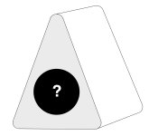
I've asked the question on the multi-way forum, but will post here too. I would be keen to know what FR driver you would suggest for this smallish stand-mounted triangular prism speaker. As I burn in the Alpair 6.2s on my home streamer, I'm becoming increasingly a member of the FR fan club. Speaker dimensions and volume will follow the driver, but volume most likely in the 4-10 litre range. Keen to seek a similar sound to my B&W 607s3s with forward mids and sparkly highs while retaining good bass performance. Can be sealed, ported or even TL (if a TL in a triangle exists!).

Attachments

  • FR Triangle.jpg
    FR Triangle.jpg
    58.6 KB · Views: 107
  • Like
Reactions: NeonDriver

Transmission line speaker? (fullrange driver)

IMG-20230212-WA0013.jpg

IMG-20230212-WA0003.jpg


Hi everyone, I made a pair of this speakers a while ago. I always though that's a transmission line or a "quarterwave" design. But is it really ?
They are made around the Tang band W8-2145 driver, blanda bowl (the large one 28cm) and a PVC pipe (about 210cm long and 6.3cm diameter). All of this sealed in a concrete base which incorporates the connectors. Sorry, I don't have graphs and mesures, but they sound good-ish to my ears.
First I designed this speaker with the 1/4 wavelenght type of enclosure, but now I'm wondering if it is a transmission line or a very long ported design.
Thank you by advance for your reply and feedback.

Building/modifying SV-S1616D 300B amp

I want to start a thread about this kit build process because after some tinkering and adjusting this amplifier sounds much better than stock, in my opinion, and will be far more reliable. So first thing I want to say is that I built this kit exactly to the guide/schematic and then started to make changes. First thing I noticed was how hot the output tubes were running. The schematic suggests running a 300b with 482 volts at the plate with 73ma plate current. In my opinion this will fry any standard 300b pretty quickly. So the first mod I performed was to bring the plate voltage down to 400. Mine was actually running at 495 and 75ma. So to get the voltage down you will need to use the purple b+ tap, not the red, and use a 5u4gb rectifier tube. This will get you to 400v and 60ma which is a more typical operating point for 300b. This is just one of the mods I have done and there are several more to discuss but I’m interested to hear about others experience with this kit before I move on to the other changes. I have attached photos of what my build looks like at this point. So please chime in if you have this kit. Cheers Thomas
0EE9A096-9B69-4B2D-AB2D-F746E79A6A86.jpeg
05F1CDEE-2B36-4FD5-BA15-F5C7A88C2B6C.jpeg

  • Locked
For Sale 3e Audio Amp and Power Supply Stuff for sale TPA3255

Hi Guys - More 3e Audio stuff that I bought and have done nothing with. Just want to move it on to someone who will make the project and appreciate it.

This is my first time and I hope it is OK.
Starting with:

AMP Balanced/unbalanced AUD85.00
PSU AUD75.00

Plus postage to wherever you are.

PayPal (family and friends.

Thanks

Dan

Attachments

  • 3e-audio-amplifier-board-stereo-class-d-balanced-tpa3255-2x-225w-4-ohm.jpg
    3e-audio-amplifier-board-stereo-class-d-balanced-tpa3255-2x-225w-4-ohm.jpg
    106.7 KB · Views: 90

New NXL550 R1.0 500 Watt MOSFET Amplifier Module

The NXL550 R1.0 amplifier module is a high performance, hi end amplifier module capable of over 500 watts into 4 Ohms and is 2 Ohm and 1 Ohm stable for short periods (60 sec).
Directly driven from an OPA462 High Voltage Op Amp.
It features the option of adding separate regulated input/driver stage supplies for even high performance.

The current power measurements were done on a +-70vdc linear power supply, higher power outputs can be achieved with voltage supplies as high as +-75 volts and with other versions that are capable of handling DC power supplies as high as +-90 volts DC.

The main PCB has an over temperature and over current LED status Flag which also serves as an output clipping indicator.

Specifications:

8 Ohms: 245W
per channel, powered from +-70vdc supply rails

4 Ohms: 425W per channel powered from +-70vdc supply rails

8 Ohms: 300W per channel, powered from +-80vdc supply rails

4 Ohms: 545W per channel powered from +-80vdc supply rails

Frequency Response: 20Hz-20Khz, -0.1db, 3Hz-210KHz, -3dB Input filter limited.

THD: 0.002%, 1khz, @200W into 8 ohms: 0.01% 10khz @200 Watts into 8 Ohms

IMD: 0.002%, @200W RMS into 8 ohms

SNR: -105dB, Unweighted, referenced to full output; -112.6dB A-Weighted

Damping Factor: 800 into 8 ohms, 100Hz

Gain: 22 (27dB) other gain options are available upon request?

Input Impedance: 22k Ohms Unbalanced:

Inputs: RCA Phono

Recommended Linear Voltage Supply +-70 Volts DC
For higher power output +-75vdc can be used.
PSU Power Transformer secondary windings 50vac (800VA)
Printed Circuit Board Dimensions 105mm x 72mm
Small form factor PCB

NXL550 R1-1A.jpg


Captured Images Showing the following.

1Khz Sine Wave driving 8 Ohm load
1khz Square Wave response driving 8 Ohm load
10khz Clipping response driving 8 Ohm load
10khz Square Wave response driving 8 Ohm load

1khz SineWave NXL550 R1.0.png


1khz Squarewave NXL550 R1.0.png


10khz Clipping NXL550 R1.0.png


10khz SqrWave NXL550 R1.0.png

Question about Potentiometer / Volume control

Hi, I have a few questions on a simple matter . Most of the amps I've built never used pots for volume control, I used the signal source's volume control ( digital ) for that .
Now using the classic volume control with a pot like this :
Amp-Volume.gif
would this affect the quality of the signal ? or , change the input impedance based on the pot's location ?. Using a buffer before the pot would help ?.

What about this , would this be a better approach ? besides the output being inverted and not being able to have " zero volume ". would this affect the input impedance as well when pot is turned ?.
betterorno.PNG


What is the best approach for this ? Best way to use potentiometer for volume control ?. ( besides using digital volume control ic's )
- Bruno.

SME 3009 S2i phono DIN adapter

Hi-

Here is my SME 3009 s2i phono din socket adapter. It may work with others, but that is the only model I have. It is made to fit this connector https://zavfinousa.com/collections/hi-fi-connectors/products/rb-250-din-socket-replacement. As well as the shield from the RCA connector.

Attachments

  • 20240624_174321.jpg
    20240624_174321.jpg
    300.4 KB · Views: 52
  • 20240624_174335.jpg
    20240624_174335.jpg
    350.9 KB · Views: 57
  • 20240624_174341.jpg
    20240624_174341.jpg
    306.4 KB · Views: 56
  • 20240625_182929.jpg
    20240625_182929.jpg
    449.9 KB · Views: 54
  • 20240625_182938.jpg
    20240625_182938.jpg
    363.6 KB · Views: 57
  • 20240625_185404.jpg
    20240625_185404.jpg
    146.3 KB · Views: 53

Chinese Lab Gruppen clone

Hi All. Om working a Chinese lab clone Model Fp20k. 3 of the channels wont output more than approx half volume. The rail voltages on the output transistors dont cross +40 x -40 Volts dc. I have encountered this problem before but with a distorted sinewave. NEVER WITH A CLEAN SINEWAVE. IT JUST GOES TO APPROX HALF POWER AND STOPS at approx 65AC output. The problem is coming from the power amp board, Not the preamp.
Does anyone have any suggestions?
Thank you.

Analogue Audio Aria 2.0 Pre Phono

Hi my friends .. someone have a service manual or schematic diagram of Analogue Audio Aria 2.0 ??
https://www.tnt-audio.com/ampli/aria_e.html I have saw probably this manual in "hifi engine forum" but the registration is closed 🙁

I have one of this, power led go on and sometimes off to interval, but at the output no signal
Thanky you for your help


IMG_3290.jpg

Dali Opticon 2 MK2 crossover inductor upgrade

Hi everyone,

I have the good Dali Opticon 2 MK2 and would like to upgrade the crossover.
Dali is known for addressing the ferromagnetic hysteresis problem in its drivers through the use of the Soft Magnetic Compound (and Dynaudio and ATC also address the problem to be honest).
Now, in order to fully benefit from the driver hysteresis reduction, I would like to minimize this problem upstream as well.
At the amplifier level I use nCore, so I'm already quite calm because of the post LPF feedback.
In terms of crossover, however, I have some doubts.
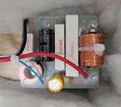
Attached is an image of the Opticon 2 MK2 crossover. I don't know much about it, but the biggest inductor I think is related to the woofer, and I also think it's of the ironcore type (and given the price range I can understand).
The small inductor instead, presumably of the tweeter, seems to me to be air core.
Now I kindly ask someone if they can confirm this.
If confirmed, I'd like to know exactly what to measure of the ironcore inductor in order to identify an alternative air core, which keeps the characteristics of the crossover unchanged.
In this sense, with the same inductance, is it possible to find an air core with the same resistance?

Thanks in advance

Attachments

  • DALI-OPTICON-2-MK2-hangfal-keresztváltó_big.jpg
    DALI-OPTICON-2-MK2-hangfal-keresztváltó_big.jpg
    410.8 KB · Views: 676

GZ34 vs 5U4 vs Diodes

Hello! I'm powering a single ended stereo using one power supply. kt88 power tubes with two ecc83 driver tubes (one for each channel)

I currently have an old stock 5U4 rectifier installed and it seemingly runs great (decent plate voltage, bias is good, etc). Below is a screen shot of my current bias/tube dissipation.

Screen Shot 2024-06-23 at 6.06.55 PM.png


My problem, is when I use a modern GZ34 (i wanted a little more voltage out of it) it blows a fuse every time.

Am i exceeding the GZ34 specs? Would a diode set-up make more sense?

TBH I'm getting 330v on the plates, while the schematic is calling for 370v. Any opinions would be appreciated, thank you!

Linkwitz Transform before or after active XO?

I've got these custom made active XOs that are 2 way 24LR with an overall system HP at 15Hz LR4 to protect subsonics. They have 3 different XO points selectable by the dip switches. Currently I intend to try 100, 300 and 500. Or near enough as my resistances got me to. It is SE input, thru the LR24 filters and then buffered into the signal trafos that do SE> balanced. Quite nice things that I hope work well for me.
IMG20240530175704.jpg

I want to try adding a Linkwitz transform to the LF section...see if my amps and woofers can handle it!
I guess I need to put the LT after this LR24 but I wasnt sure about the balanced output of the trafos into an SE LT PCB. I'm sending the LF section of this XO into mono 3255s that accept a B input so would be a shame to lose that.
So can I do the LT on the 'entire' signal before the active XOs when I'm all still in SE? I didn't know about sending a boosted LF signal thru the trafos.
Thanks

System with both active and passive subwoofers

I have a set of MB Quart QM340CX which is separated 3-way speaker system comprising 1” tweeters, 5.25” midranges, 10” woofers, and 3-way passive crossover networks. I also have a pair of 8” KEF KAR 200B subwoofers. I plan to use them with a 5ch amplifier; Soundstream Reference 405. The 405 can be used in 3 channels mode, by bridging ch1 with ch2, and ch3 with ch4. Anyway, the midranges and tweeters will be installed at the front doors and the subwoofers are planned to be installed on the rear parcel. Because the MB Quart subs utilize PASSIVE crossovers while the KEF subs will receive filtered signal from the 405’s built-in ACTIVE crossovers, I wonder if installing those 8” KEF and 10” MB Quart on the same rear parcel, will the sound that is formed by different signal interfere with each other and causes bad sound?

The Denon DCM Series CD Player Repair Thread

Since so many of these inexpensive players seem to have a high rate of failure, I thought it would be a good idea to have a thread dedicated to their repair.

I'll start with the player I'm currently repairing 😉. I bought a DCM-370 from a seller who openly disclosed that the player needed repair. When it arrived, it would play bits and pieces of audio throughout a disc, with a lot of long-distance skipping. After attempting to clean the lens, lubricate the gears, etc., etc., the problem didn't improve. Actually, the more I used it, the less it played until it eventually couldn't even read the TOC.

Knowing that most instances of these problems were solved either by replacing the laser or the sled / spindle motors, I elected to purchase a whole new assembly (pickup, mechanism, everything). When I put it in the player and tried it out, it wouldn't spin the CD. I figured the spindle motor on the new assembly was dead. To confirm it, I took the new laser and put it on the old assembly. Still no spin. I thought this was odd, so I put the old laser on the new assembly, and lo and behold, the disc spun! However, it made the same clicking noises it had when it was on the old assembly and failed to read the TOC.

Any suggestions?

Transformer Leads Gauge Quick Question

Hello, I just received this PT, 225VA, 230V to replace the old 120V unit, maker is Amplimo Holland/UK, they made the old one so it should drop right in (famous last words). Only thing I noticed are the very thin primary leads, solid core and about 22awg, apparently they are the winding run outside about 20cm as flying leads. I've seen this before on tiny units in old radios never on a big transformer, off hand seems a little worrying connecting these to the 230V mains. Every other PT I've used of whatever sort had stranded leads spliced on and buried inside under the tape. From the PT to the switch will be right around 20cm, not very long, so I'm guessing the leads will be fine but thought I'd ask just in case.

My instinct is to splice on 20 or 18awg leads right at the exit of the wind, solder, shrink, fit a bit of vinyl tubing over it all for aesthetics, and off to the races. Thin solid core likes to break too unless handled carefully, not that I intended to handle it much. But, I've also learned to leave well enough alone, don't look for trouble, don't cut wires that don't to be cut, and assume the maker knows more than I do.

Curious what people think, is it 100% safe to connect to the switch and mains as is? Better to splice on thicker stranded wire?

Amplimo Primay Leads copy 2.jpg


Old 120V PT still in place:

2.jpg

Pipe Dreams … 50hz Helmholtz resonator out of PVC pipe. Bass trap or money trap?

Be gentle please
😉
looking for some advice on PVC pipe resonators 
Pipe dreams??????
Trying to get rid of this 50hz hang in the room. Got some PVC pipe and got them to resonate at the frequency I wanted. Three 10ft pipes basically cut in half and a neck added to lower frequency. Added some poly fill to see if it did anything. Do I do 3 more or am I just wasting my money?

https://vimeo.com/894328084/979b8b537f?share=copy

Before and After 80ms-160ms Decay.jpg

Class G type cascode buffer

I just read from the latest tubecad blog that Nelson had in the past a design where a cascode is used to create a very efficient Class A buffer amplifier. Principle is similar to Class G but the higher cascode Mosfets (used for high power) are slightly biased at all time to avoid switching in and out when higher power is needed. Seems like a very interesting concept but I do not notice any discussion on this concept in this forum so far. Is there any reason why this concept never becomes a working project? I am planning to test out this concept and build a 20-25W class A buffer.
https://www.tubecad.com/2024/06/blog0603.htm
  • Like
Reactions: wdecho

Hello from Brisbane Australia

I'm a hobbyist woodworker who enjoys good music Jazz Indie and more. All my woodworking projects so far (mostly furniture we use in our home) helped me learn a new skill. I would like to try my hand at building a really good looking and sounding set of speakers and I am sure this will test my skills and teach me a few new ones. I found some interesting discussions in this forum, so I decided to join in the fun.
  • Like
Reactions: Stanislav

Toroidal Transformer for QUAD 606

I have just bought a replacement Toroidal transformer asked for Secondaries: 2 x 0-80V.
What i actualy got was (80v 0v 80v) which is only one center tapped winding.
The quad power supply circuit shows two independant windings which is why i asked for 2 x 0-80v
windings.
I have attached a screen shot showing the quad power supply with a separate winding for each channel with a virtual earth.
My qustion is will the power supply circuit still work now the transformer windings are actually effectively
connected to give center tapped 80v 0v 80v. see attached screen shots.
Each rectifier will now be connected together at the center tap.

Attachments

  • QUAD 606 SEPARATE SECONDARY.png
    QUAD 606 SEPARATE SECONDARY.png
    68.7 KB · Views: 156
  • QUAD 606 CENTER TAPPED SECONDARY.png
    QUAD 606 CENTER TAPPED SECONDARY.png
    71.7 KB · Views: 180

Muffsy is distorted, Why?

With record on the platter, tube line stage and tube amps warmed up I set the needle down carefully on the record. No hum but rather distorted sounding. After trying different cartridges it was still distorted and my hopes were somewhat let down.

I pulled out a record I knew was in great shape because it had only been played one time in its life still no joy. I played with the gain switches still no help. I pulled out the input opamp a OPA2134 and replaced it with the only thing I had laying around which was a TL082 and fired it up again and it wasn't distorted but it sounded kind of lifeless. I surely shouldn't be overdriving it with a Pickering XV-15 D1200 cartridge which should output 5mv.

What could I have done wrong? Power supply measured correctly at +15.16 & -15.12 voltage on opamp pins 4 & 8 is correct

Any ideas?

Naim Nait 5 Service Manual wanted

Hello all fellow members and friends, I am looking for a service manual or schematics for Naim Nait 5 (not "i" model) amplifier. The problem of this unit is that the signal levels on both channels are not equal. Investigating the signal path, I assumed digital volume control is not working with same way for both channels OR signal level is not equal before this. Unfortunately, it is too difficult to decrypt circuit without schematics.
Thanks anyone who will reply.
Regards,
John

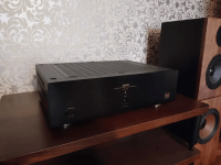
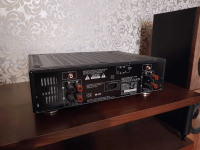
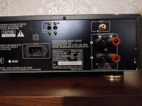
For Sale Amplifier Denon POA T10

p23q0y9i.png

Hello for everyone..
I am selling here my Denon POA amplifier in perfect working conditions and mint appear, selling here
because I do have more equipment of the same kind but can't stay with everything also for invest in
other stuff so looking for a new owner. payment by PP
Price is 440€
Regards

Attachments

  • tyiougua.png
    tyiougua.png
    272.8 KB · Views: 122
  • w0ukcn3k.png
    w0ukcn3k.png
    275.3 KB · Views: 134
  • 7pb8ydd5.png
    7pb8ydd5.png
    304.4 KB · Views: 139
  • vgogmb3u.png
    vgogmb3u.png
    271.9 KB · Views: 149

Vituixcad - getting started, apply baffle step simulation?

I am just learning Vituixcad. I have managed to model my crossover for a relatively simple 2.5 way tower speaker using the Satori 6.5 papyrus midbass and the TW29 silk dome tweeter.

I am using the ideal /infinite baffle traces for now, as I am still building my enclosures.

I see that I can use the Diffraction tool to model the baffle step that my front baffle would cause.

However, I am unclear how to apply / overlay this baffle step back to my response graphs? Is this possible?

60 degree quite compact 3 way Synergy horn

Curiosity and wanting to make something got me into looking at the feasibility of a 60 degree Synergy horn.

This would be purely for Hifi volume listening / Home Theatre use.

Using 2 x 8" LF drivers - Faital 8PR200s (as the SM60F) or Eminence Beta 8As (I know I like the Eminence Kappa 12A sound, but don't know if that counts for anything, but they are cheaper).. or plenty of other 8" drivers.

For MF and HF - instead of going coaxial, how about a 2.5" or 3" (if it would squeeze on), sealed back paper cone driver pair, or even 4 of?

There are plenty of 100Hz to too more than plenty high small drivers.
Peerless do a closed back one that's looks good.
Dayton and others do too.

Then on HF my trusty Vitavox S2 compression drivers.

I know I like the S2 sound - already used them on Tractrix and Le Cléac'h horns and have them currently on the SH50-alikes I made, after trying and not finding the BMS4550s to my taste.

I've been measuring up and jiggling a to scale'ish plan drawing.

Could be done with similar compact 530mm square flare as the SM60F.

I've not finalised the tap and port placings yet, but something like this.

Simple drawing for websites.PNG


What do the Synergy builders reckon?
Method or madness?

What is this called???

I have seen in a YouTube video a few months ago how they reduce the center to center spacing of a subwoofer array by covering each driver with a plate with two oval holes.

This is supposed to turn one driver into two separate point sources.

Is there a technical term for this? I scoured the net for an hour without any result.

I am trying to find out if;

....it really works
.....can it be done to midrange array
drivers too?

I have a pile of wonderful 12cm full range drivers that I want to cross over quite high ( around 6Khz) to a tweeter array.

For Sale Brand New Pair SB Acoustics Satori 6.5" Woofer Driver MW16P-4 MW165DC-08N36-DA00

I am selling a Brand New Pair SB Acoustics Satori 6.5" Woofer Driver MW16P-4 MW165DC-08N36-DA00 in the Original Boxes.

I am the original owner and bought them from an authorized dealer a few years ago.

They are never mounted them or hooked up and factory perfect in every way! Absolutely not used and not mounted!

Too many projects on hands and no time for speaker building so I am offering them up for others to build.

Price is $250 plus shipping fees.

Satori MW16P-4 Woofer - Black - 4 ohm


Satori is a Buddhist term for enlightenment. The word literally means "understanding". Satori translates as a flash of awareness. Satori drivers are designed for subtlety and realism.


  • Egyptian Reed Cone
  • Vented aerodynamic cast aluminum chassis for optimum strength and low compression
  • Proprietary cone material with EGYPTIAN PAPYRUS fibres made in-house
  • Soft low damping rubber surround for optimum transient response
  • Advanced BIMAX spider for improved linearity
  • Powerful optimized low distortion neodymium motor system
  • Non-conducting fibre glass voice coil former for minimum damping
  • Extended copper sleeve on pole piece for low inductance and reduced distortion
  • CCAW voice coil for reduced moving mass
  • Long life silver lead wires attached 180° apart for improved stability
  • Vented pole piece for reduced compression
  • High piston to chassis diameter ratio
  • Gasket and bolt hole protrusions for reduced coupling to speaker cabinet

Link to PDF specification sheet download.

Satori1.jpg
Satori3.jpg
Satori2.jpg
Satori4.jpg

Greatest Bookshelf Speakers Ever?

Over the past couple years I have been testing many (...😅) drivers for a (preliminary) three or four way speaker design. Having tested nearly everything of interest to me, my conclusion is that a single low mass yet robust 4"-5" full range driver is ideal. Furthermore a speaker like the Omega Super 3 is an interesting adaptation of this simple, utilitarian, and most optimal approach. The optional incorporation of a tweeter at 1000hz or higher and a woofer at 100hz or lower yields additional advantages depending on the goals of the builder and listening distance.

Having tested the majority of drivers of interest to me, I'm curious what the absolute best sounding bookshelf speakers of all time that feature proprietary drivers. One example that comes to mind is the Audience A3S2. In addition having heard the KEF Meta Blades I prefer the performance of small diameter Mark Audio drivers over KEF coaxial. A coaxial driver is ideal though the higher mass of the mid section of the KEF driver is its limitation compared against the lower mass small Mark Audio drivers. Is there a proprietary 4"-5" driver, unavailable to the DIY community, that exceeds the performance of what is available to the DIY community?

Why is my 2ohm subwoofer showing as 8ohm?

Im using a multi meter
to ohm setting
i have a Alpine R-W12D2 Subwoofer. dual voic coil

It doesnt matter how i connect it the multi meter shows 8ohm?

how is this possible if this is a new certified 2 ohm subwoofer?

Can someone help me as I have 2 of these subs and I have a 1000 watt RMS JL Audio JX1000/1d amp but i believe it runs at 500 watts if the subs are 4ohm

Just really confused, and figuring the best way to wire these subs, but the 8ohm showing doesnt make sense unless im doing somthing wrong?

1719231935329.jpeg

The Omnipressor

Has anyone heard of the Eventide Omnipressor? I'm curious because it could make for an interesting compressor discussion but I'm not sure what Forum it belongs in. I reverse engineered Walter Becker's personal unit and built my own version and demonstrated it for one of Walter/Donald's producer friends and he liked it better than Walters. It was fun to take a deep dive into such a weird compressor.

becker-omnipressor.jpg
This also gets into a discussion about VCAs and I find that pretty interesting too.

DIY progress report

Zen Variations part 4: Text still needs writing, PC boards
are going out for fabrication. ETA end of July. We will be
making the boards available for sale.

The Claw. The horns are taking up a lot of space on the
shop floor, but progress has been slow. ETA this fall.

El Pipe-O. A 12 foot transmission line with a 24 inch diameter
and two 21" woofers. A little project intended as a filler that
got out of control. Prototypes and documentation are done,
only text needs writing. ETA August.

Active Crossover. Waiting in queue after above 3 projects.
PC board will be available. ETA September.

Zen Variations part 5. Big change of direction! ETA October.
  • Like
Reactions: Stefano

Calculation possible at all? Studio Monitors

Hi,

I'm completely new to Speaker design. I'm a producer/mixer hobbyist. But I've studied physics almost 20 years ago, so it should easier to understand things here.
About my project: I need good nearfield studio monitors. Studio Monitors are not like Hifi Speakers, they don't have to sound nice, they have to sound neutral,, objective, linear with low THD over all freqs.
A guy I know (who's really a good sound engineer pro) said, I have to pay at least 10'000.- Euro inkl. Amp. He has the Strauss se-nf-3 nearfields: https://strauss-elektroakustik.de/se-nf-3

they cost about 3'500.- Euro/piece.

He has also the bigger ones (midfields): SE-MF4 or 2.1.
They are all passive and 2.way. He says also, the nearfields are by far the best in this price league, and below that price, nothing is serious.
I searched a bit in the internet, and this Strauss speakers are just these few models, all 2-way and passive. I watched also vids on youtube, with Jürgen Strauss talking.

As I read for the se-nf-3: it's a 5" Mid/Woofer with 1" Tweeter, Crossover-f @1.2k
I've read, it seems to be a Scanspeak 5": 15w-8530k00 or 8531
And could be a wavecore or a Scanspeak D3004/660000 Tweeter.

When I calculate the components, a box will cost max. 800.- Euro for a box.
I will definitley not buy these boxes.

During the last days, I read all day long things about building loudspeakers, mainly the "loudspeaker-design-cookbook" and "high-performance-loudspeakers-optimising-high-fidelity-loudspeaker-systems" (Martin Colloms). I've also watched measurement-Vids on youtube and checked some online/calc. Software (vituix.cad).

As I see it: you can just calculate some very simple things (e.g. fb of vented box), but already for the baffle step, simulation will not fit sufficiently to the reality.
Is this true?

I don't want to build these se-nf3 because dimensions don't fit to my room/place. I want to build my own.

Also very strange: I've measured the dimensions of these se-nf-3, tried to get inner vol.. When I calculate the vent length I come to a length of about 50cm, which is quite long.
When I take a look at these se-nf-3 with my knowledge after a few days, I have the impression that this shape isn't the best for a box. All these Strauss boxes look like he took just the simplest shape.

Perhaps you can give me some input.

Tom
TDA7294 - Two Modules on one Center Tapped Transformer

I have a Russound X75 that no longer works and I found that one of the TDA7294 chips was blown; when attempting to remove it the traces were so worn they fell apart.

I want to buy a pair of the below modules to install, but since each board has its own rectifier is it ok to split my transformer to power a pair of boards? The transformer is a 27-0-27V Center tapped. Can I split each wire into two to run to each board, or is it better to remove the rectifiers from both boards, use a single rectifier, and split my signal off the rectifier as DC voltage
Here are the boards I am considering buying.
https://www.amazon.com/DEVMO-TDA729...054bc2&ref_=pd_hp_d_atf_ci_mcx_mr_ca_hp_atf_d

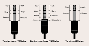
Why doesn't the Bluetooth neckband have a common ground? Right side (R-) & left side(L-) is not common

I'm building a Bluetooth receiver from Bluetooth neckband circuit. i have to connect the output to 3.5 port so that I can plugin all wired earphones.

I have identified both Right side (R-) & Left side(L-) is uncommon. My multimeter didn't found any ground connection.
I merged Right side (R-) & Left side(L-) and connected to the speakers. It sounds ok but when I do right /left stereo check, it didn't perform good. while testing, there was a leak audio on the other side against the playing side.

please share your suggestion/solution.

Attachments

  • neckband.JPG
    neckband.JPG
    46.4 KB · Views: 65

Hello from Rhode Island

Hi, This is my first post, I have been working on tube amps since I worked at a TV repair shop back in the 70's. I recently built a 300B amp based on Skunkie designs, https://www.skunkiedesigns.com/300b , I altered the design, instead of DC filaments, I used AC filaments on the 300b tubes, the AMP came out better than expected, no hum at all. I used Hammond transformers, which I believe also help make some improvement.

I also purchased the Digilent Analog Discovery 3 board, which I use with the Audio Analyzer Suite. This gives me somewhat accurate THD vs Power reading of any amp (plus many other features, like freq resp, IMD, etc), it is very helpful in seeing how well an amp actually performs from low power to full power and beyond. It recently help me find a bad signal tube that was crapping out at about half power. It too me about 5 minutes to find it, this is my favorate tool now.

I am currenly looking for a 25-30W push-pull, point to point wired stereo amp, that I would like to build this fall, if anyone has any ideas, please let me know.

Norm

Which amp for 25W 8ohm transducer

I have this Dayton Transducer and I wanted to know which amp specification will give me the best result for driving it? (Meaning no distortion at maximum volume)

what I should calculate using ohm law?
what will be the difference if using 12V amplifier vs 24V amplifier? what I should consider checking if my transducer is 25W 8ohm vs 25W 4ohm?

Thanks for any clarification

Brand New AE Acoustics Elegance 4 x TD-18H Dipole, 4 x TD12M, 4 x TD15M Drivers For Sale

I have Brand New AE Acoustics Elegance 4 x TD-18H Dipole, 4 x TD12M, 4 x TD15M Drivers For Sale. I am the original owner and purchased them directly from AE Speakers many years ago for my DIY Speakers.

But I didn't have time to start the project so they are Brand New unused and in perfect factory condition.

I have 4 x TD-18H Dipole Drivers, 4 x TD-12M, 4 x TD15M and you can make a fair offer on each driver type.

I will ship them in the U.S.A with FedEx Ground insured only.

PayPal is the Preferred payment method but you must have a confirmed shipping address.
  • Like
Reactions: camplo and taloyd

Drive NOS AD1865/62,PCM1704/02/63,TDA1541 from FIFO: Universal I2S-PCM driver board

Rather than I2S signals, most of R-2R NOS DACs (PCM63, AD1865, AD1862, PCM1704, PCM1702, TDA1541...) driven by LL/LR, DL, DR and BCK. I might be wrong, but to make it easier, I call them “PCM” signals.

Usually those signals are generated by digital filter chips (DF1704, PDM100, SM5842/43/47...). However, for applications such as NOS mode, software based up-sampling mode, or to interface directly with FIFO KIT, we don’t need that digital filter. In this case, how to design a low jitter I2S to PCM driver daughter board becomes an issue.

Zinsula, vzs and other members provided a lot of good suggestions on this driver board, I summarize those the requirements as blow

1. Support 16,18,20,24 bit PCM format
2. Support PCM63,AD1865,AD1862,PCM1704,PCM1702,TDA154 and other 2-2R DAC
3. L,R simultaneous timing, latching at same latching edge to eliminate L/R phase difference
4. Bit clock can be stopped after data shifted into DAC to reduce DAC noise floor further
5. Optional tail clocks after latching work for PCM17XX DAC
6. Optional one leading clock to “warm up” logic state machine(may not need in most of cases)
7. FPGA/CPLD based low jitter synchronized logic design clocked by MCLK only
8. High speed design capable for 384KHz Fs with maxima MCLK over 100MHz
9. Support dual mono DAC mode
10. Very high speed re-clocking at last stage optimized for low jitter performance
11. Daughter board architecture can stack on top of the FIFO clock board

I started this I2S to PCM driver daughter board project a couple of month ago. Now I’m almost done. Here are some previous progresses posted on the FIFO thread:

http://www.diyaudio.com/forums/digital-line-level/192465-asynchronous-i2s-fifo-project-ultimate-weapon-fight-jitter-33.html#post2980088

http://www.diyaudio.com/forums/digital-line-level/192465-asynchronous-i2s-fifo-project-ultimate-weapon-fight-jitter-35.html#post2983484

http://www.diyaudio.com/forums/digital-line-level/192465-asynchronous-i2s-fifo-project-ultimate-weapon-fight-jitter-36.html#post2985663

http://www.diyaudio.com/forums/digital-line-level/192465-asynchronous-i2s-fifo-project-ultimate-weapon-fight-jitter-39.html#post2989034

http://www.diyaudio.com/forums/digital-line-level/192465-asynchronous-i2s-fifo-project-ultimate-weapon-fight-jitter-40.html#post2991350

http://www.diyaudio.com/forums/digital-line-level/192465-asynchronous-i2s-fifo-project-ultimate-weapon-fight-jitter-40.html#post2991644

http://www.diyaudio.com/forums/digital-line-level/192465-asynchronous-i2s-fifo-project-ultimate-weapon-fight-jitter-40.html#post2991670

http://www.diyaudio.com/forums/digital-line-level/192465-asynchronous-i2s-fifo-project-ultimate-weapon-fight-jitter-43.html#post2995428

http://www.diyaudio.com/forums/digital-line-level/192465-asynchronous-i2s-fifo-project-ultimate-weapon-fight-jitter-47.html#post3016242

http://www.diyaudio.com/forums/digital-line-level/192465-asynchronous-i2s-fifo-project-ultimate-weapon-fight-jitter-59.html#post3041836

http://www.diyaudio.com/forums/digital-line-level/192465-asynchronous-i2s-fifo-project-ultimate-weapon-fight-jitter-60.html#post3043110

http://www.diyaudio.com/forums/digital-line-level/192465-asynchronous-i2s-fifo-project-ultimate-weapon-fight-jitter-60.html#post3047114

http://www.diyaudio.com/forums/digital-line-level/192465-asynchronous-i2s-fifo-project-ultimate-weapon-fight-jitter-81.html

http://www.diyaudio.com/forums/digital-line-level/192465-asynchronous-i2s-fifo-project-ultimate-weapon-fight-jitter-88.html

regal suggested me opening a new thread for this project. That makes sense. NOS DAC and DS DAC belong to different application. It’s not good mixing them up.

Will start evaluating this daughter board very soon.

Ian

Attachments

  • BlockDiagram.png
    BlockDiagram.png
    58.3 KB · Views: 12,006
  • PCMdaughterBoard1.JPG
    PCMdaughterBoard1.JPG
    452.2 KB · Views: 11,696
  • PCMdaughterBoard2.JPG
    PCMdaughterBoard2.JPG
    414.7 KB · Views: 11,153

Australian in Detroit, embarking on a system build

Hi everybody!
Long time lurker/learner, first time builder here.
I'll be most active on @weltersys SynTripP: 2-way 2-part Virtual Single Point Source Horn thread, as I am about to embark on a build of those beauties.
In general we host parties here in Detroit and are hoping to have the system running before the end of summer 2024!
Wishing you all a flat response with low distortion at high power levels,
octapotamus

CBT24*SB65 measurements

Hi evryone

First i would like to thank Jim Griffin ; i decieded to build my CBT speakers when i discovered this thread . You can see what i did in my introduction message .

Nevertheless the lack of measurements is surprising , the same with regard to EQ . Yet these speakers are easy to measure : in a room 4 / 5 / 3,5 m i obtained an anéchoic window of 9 ms with the mic 1 m distance / 1 m height .

Without EQ i get that

mesure brute array.jpg


As you can see you can't listen to this as is

Counterpoint SA-100 MOSFETs Source?

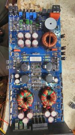
Have a Counterpoint SA-100 in the shop. In addition to all the HV caps having exploded during customer use, I have determined that all of the MOSFETs are bad as well.

There seem to be almost no sources for 10N12, 10P12. Even the Exicon substitutes (which require rewiring and bias circuit mods) are obsolete and non stocked. Then tehre's the BUZ 900D/905D.. no one has them in sufficient quantities to repair this amp. And the ones that are available are about $48 each x 8 pieces.

This is a last ditch effort to find a source at a more reasonable cost. I hate to tell the customer his amp is unrepairable.

High pass filter for Quad II

If this is a really stupid question, please make allowances... Is it possible to put a high pass filter between a solid state pre amp and a Quad II power amp? I'd like to avoid an active crossover and filter out <80hz, but my somewhat blundering attempts at research seem to show that it would involve a 0.13pF capacitor (if the input impedance of the Quad is 1.5M) which would have to be ceramic?
I have used a 100nF film to do the same job between the pre (Kenwood C1) and a Yamaha power amp with 20k input impedance, and that works very well, but I would like to try the Quad with the same speakers and pre amp.

SWTP products

https://www.diyaudio.com/community/threads/jlh-10-watt-class-a-amplifier.3075/post-7716150

You were very lucky to have anyone in your life to support your electronics interest. I was in high school, about the same time (~1969), and had very little money to spend, most of which I spend on magazines like those that advertised SWTP.

I found my "Lil Tiger", or what became of it in the basement. It probably still works but I just keep it for sentimental reasons. It drove a sub-woofer and is built into a box with the XO. Not a lot of power but it sounded fine. No one I knew had ever heard of using a sub in those days, so it impressed a lot of people.

P1000532.JPG

Help with power supply for preamp

https://www.aliexpress.us/item/3256...BzA&mp=1&gatewayAdapt=glo2usa#nav-description

I want to buy this pre-amp for an upcoming project and am unsure on the power supply. I really don't understand why dual power supplies are so hard to find when so many things require them. Anyways it calls for a 12 0 12 AC to 15 0 15AC supply but I want to use a SMPS and a voltage splitter module like this. What range of VDC do you think Id be safe to power that pre-amp with? Would 15vdc-20vdc be safe to assume is ok?

Must-Play Tracks to Test Your Hi-Fi System

Hi everyone, I wrote a Medium article titled "Audiophile Essentials: Must-Play Tracks to Test Your Hi-Fi System." It features a list of tracks perfect for testing the quality of your audio setup. Whether you're tuning a new setup or simply wanting to appreciate the nuances of your high-fidelity system, these tracks offer a range of frequencies, dynamics, and complexities that will truly showcase your system's capabilities. Check it out and share your thoughts!

Read it here: https://medium.com/@rasansmn/audiop...tracks-to-test-your-hi-fi-system-1cde41ca756b

Looking forward to your thoughts and recommendations!

Please Help! Sansui AU-7500 Pulsating Pre-amp

Help, im currently repairing this AU7500, at first relay clicking in and out like crazy so i isolate Pre-amp and main in by removing horseshoe connector between them, turns out the pre amp is the problem, since i dont have an oscilloscope, i chased the 1khz signal through preamp using and earphone in series with a 200 ohm resistor and a probe, signal passes through TR701, and TR703 just fine up until the base of TR705 after that 1khz signal is kinda fading in and out through the emitter of TR705, i already replaced it and TR707 with KSA992 and it still doing it, i also replaced the electrolytic caps around it , the components around them also tested fine.. Both Channels are doing this. im just clueless now.. help..

Attachments

  • Untitled5.png
    Untitled5.png
    111.3 KB · Views: 92

Noon questions

Hi guys

I am new to speaker DIY
I got two old Fostex 103 (not Sigma) labeled with Dynaco free. The guy said the mighty need some refurbishment.

It seems the speakers are broken or do I do something completely wrong?

What did I try?
I took a small amplifier and a Pc with spotify. I hooked up the amp with the speakers . The amp is switched off. Switch on the amp. Press play. The speaker's membrane are not moving

Plugged off again everything
I checked the membrane, softly trying to press a bit downwards but the membrane doesn't move at all

Is the speaker completely broken or do i do something wrong

Thanks for help

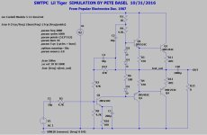
SWTPC Lil Tiger Amp (18W) SPICE Simulation

Note that I don't suggest that anyone build this amp since it is overly simplistic.

The SWTPC Lil Tiger was their smallest amplifier with undersized TO-126 output devices that blew up
when driving 4 ohm loads. It was also overly simplistic as can be seen from the schematics. I was gifted
one channel circuit board and parts kit for Christmas in 1967, built it and it worked, and another a few
months later for stereo. It was my first SS amp that worked. I'd tried building some from Ge transistors
but none of them lasted for more than a few seconds. Mine blew up many times while driving 4 ohm
speakers and I didn't realize that larger output devices were needed. I still have it, not working, and
decided to simulate it for kicks back in 2016. I might rebuild it just to have it working as the first amp
I ever built.

I'd probably use BD911/912 or TIP35/36 as off board outputs if I rebuild this amp, then it should be fine
into 4 ohm loads and probably survive shorted outputs. I'd also use BD139/140-16 as drivers when much
bigger output devices are used. I also will post an EF3 output mod version simulation in another thread.

A zip file is attached with the LtSpice files, it is set up to run distortion analysis but it can be changed for
different .tran or AC analysis. Note that I used modern sensible replacements for the transistors from
Bob C's checked transistor model file. Again use bigger outputs rather than the ones shown if anyone
tries to build this.

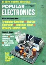
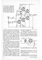
Anyway, here are some pictures and a link to the full article from Popular Electronics December 1967:
http://swtpcemu.com/mholley/PopularElectronics/Dec1967/PE_Dec1967.htm

PE_Dec_1967_Cover.jpg

PE_Dec_1967_pg30.jpg

SPICE LILT ORIG.JPG

Attachments

TL Stuffing and impedance peaks

Hi all,

I was helping a friend set up some new transmission line speakers that he built. They are a simple 1/4 wave straight line with no taper. With no stuffing, the mids sounded predictably funky and the bass was quite heavy. We ran an impedance sweep and there was a prominent spike around 180 Hz, which correlated nicely to the height of the folded line. There were other spikes also, at higher frequencies. So far, this was about what I expected. Then we added stuffing to the first half of the line starting at the woofer to the first fold. It sounded much better, as predicted. Now there is an impedance peak around 280 Hz and the higher spikes were no longer visible.

The lowest spike of 180 made sense to me, but why did it appear to move up in frequency when we added stuffing? The new peaks wavelength is about 12", which may relate to the distance from the beginning of the line to the beginning of the stuffing. Could the pressure wave be reflecting off of the stuffing? I don't know how else to explain it.

Thanks for any insight...

System One conversion to APWIN

Good afternoon,

I use the s1usb adapter together with my System One DSP Analyser.
Could you please help me at the conversion of my System One Tests in APWIN like in the ap manual:
https://www.ap.com/category/news/translating-system-one-dos-files-to-apwin-ap2700-or-ats ?
According to the notes it will be necessary to have APWIN 2.14 and 2.24 installed, but at RELATED DOWNLOADS (bottom at the end of the conversion-manual) only exist a download link to APWIN Control Software v2.24 without link to the v2.14.
Could somebody please send me the download link or the installation package for the APWIN Control Software v2.14?
It would be great and very helpfull for me!
Thanks in advance.

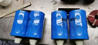
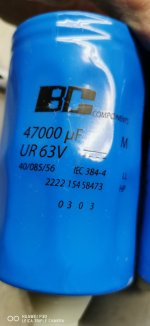
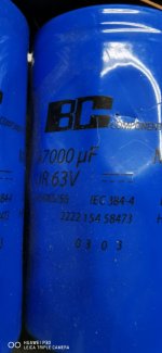
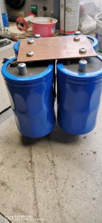
For Sale Vishay BC Components 4 x 47000uF 63V

For sale: 4 pieces of Vishay BC Components 47000uF 63V including the copper sheet or 8 pieces as shown in the pictures. The size of each capacitor: D:66 mm x H:105 mm. See Digikey / MAL210618473E3. I’m asking for 120 € for the Quad Capacitor bank

https://www.digikey.lv/en/products/...draloric-bc-components/MAL210618473E3/5636542

I would send them within the EU because the shipping costs are less, but this would also be possible outside the EU. However, the shipping costs would be higher. Shipping with DHL + 5% PayPal fee.

Attachments

  • BHC 47000uF 63V (1).jpg
    BHC 47000uF 63V (1).jpg
    307.8 KB · Views: 74
  • BHC 47000uF 63V (2).jpg
    BHC 47000uF 63V (2).jpg
    181.4 KB · Views: 78
  • BHC 47000uF 63V (3).jpg
    BHC 47000uF 63V (3).jpg
    263.3 KB · Views: 68
  • BHC 47000uF 63V (4).jpg
    BHC 47000uF 63V (4).jpg
    144.5 KB · Views: 77
  • BHC 47000uF 63V (5).jpg
    BHC 47000uF 63V (5).jpg
    245.7 KB · Views: 79
  • BHC 47000uF 63V (6).jpg
    BHC 47000uF 63V (6).jpg
    157.6 KB · Views: 74
Projects by fanatics, for fanatics
Get answers and advice for everyone wanting to learn the art of audio.
Join the Community
507,669
Members
7,883,466
Messages

Filter

Forum Statistics

Threads
405,990
Messages
7,883,466
Members
507,669
Latest member
dukerd74