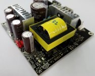
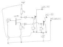
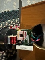
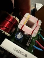
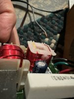
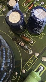
Shorted Harman Kardon main board (I think)

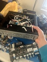
Hi everyone I'm triyng to repair an harman kardon ts2bq/ts11/I don't know how many name this subwoofer has...
The first problem was literally a hole big such a finger in the amplifer board with shorted mosfet and blowed up capacitors. After having fixed the amplifer board I've tied to turn it on, the results are two shorted mosfet and another problem.
After several tests with the tester I'm stuck, if I put the tips in the positive and negative of the diode bridge for a few seconds the tester tells me that there is a short circuit, after the value continues to rise up to 1560, after a few minutes it goes back to how it was before. I did these tests by removing the diode bridge (to check that it wasn't that) and removing both the amplifier board and the jack board.
What component can have this behavior? Could someone help me?
This is the datasheet

Thanks

Martin Logan ESL upgrades

The cheapest Martin Logan ESL is a good value for the money. Can we make it a little better with a little effort? These are the things I successfully tried:
  1. Linear power supply. You don't even need to buy that fancy 'audio' power supplies. A normal, stabilised, linear (with a transformer) power supply also helps a lot. I tried something for $10, 15V, 1A, with a 5.5/2.1mm DC plug, plus in the middle.​
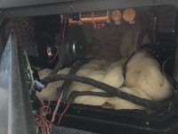
  2. Bass is probably the part where ML ESL is the weakest. We can at least try to mitigate some problems here. Adding a weight to the speakers could help. I had granite coasters laying around, that almost fitted perfectly. Also, it seems that the enclosure has some resonances, so I added self adhesive bitumen pads inside. That was very helpful for quality of the bass. When being at it, changed the filling to wool.​
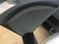
  3. Unfortunately I couldn't place the speakers far enough from the wall. The back wave was messing the sound too much. Ideally it should be diffused behind the speakers somehow. Probably with some acoustic system on the wall. Anyway, I couldn't find anything aesthetically pleasing enough. I had to damp the back of the panel with an acoustic mat. It worked well for the purpose.​
  4. Next step was checking if bypassing the caps in the crossover can be beneficial. The result was also promising. Caps bypassed with 1% of the original values. It helps with resolution and smoothes the highs.​
Do you have any other modifications that can be easily tried?

Attachments

  • IMG_0499.jpg
    IMG_0499.jpg
    161.2 KB · Views: 642
  • IMG_0500.jpg
    IMG_0500.jpg
    176.4 KB · Views: 686
  • IMG_0502.jpg
    IMG_0502.jpg
    126.7 KB · Views: 816
  • IMG_1363.JPG.a8919d3316b1aec020cb87e2cdc017d4.JPG
    IMG_1363.JPG.a8919d3316b1aec020cb87e2cdc017d4.JPG
    156.9 KB · Views: 617
  • IMG_1364.JPG.8ed0103b7b823bad4566668744a6718c.JPG
    IMG_1364.JPG.8ed0103b7b823bad4566668744a6718c.JPG
    105.2 KB · Views: 599
  • IMG_1834.JPG.743199108f4dedf6d46790850a75bb47.JPG
    IMG_1834.JPG.743199108f4dedf6d46790850a75bb47.JPG
    79 KB · Views: 583
  • IMG_1835.JPG.75c95042b63a9a43b6420ac39aa4d4ea.JPG
    IMG_1835.JPG.75c95042b63a9a43b6420ac39aa4d4ea.JPG
    102.3 KB · Views: 587

For Sale Selling: Sony VFETs / SITs 2SJ28 and 2SK82 (fully tested with curve tracer and Vgs data)

Edit March 2024: You want parts? Read this post carefully. Do what it says, all of it. Otherwise your PM might not get an answer.

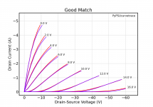
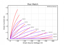
I have a bunch of Sony VFETs 2SJ28 and 2SK82 parts for sale. All parts were tested for gate-source voltage (Vgs) at ±1.6 A drain current (Id) and ±20.0 V drain-source volatge (Vds). There are full curve traces for all parts (Id vs. Vds at Vgs = 0, ±2, ... , ±16 V).

The parts were matched by "curve matching" as explained here.

If you are interested in getting some of these parts:
  • Take a look at the parts lists with parameters (Vgs, gm, μ), curve matching, and curve plots:
  • Select your parts:
    • I recommend to first look at the curve-matching list available at the links above. In short, a low delta-Vgs means a good overall match. Read this to learn how the curve matching works.
    • The parameters list may also be interesting.
    • This post may be useful to learn about parts matching based on their curves.
  • Send me a personal message (PM) here on diyAudio with your part numbers and complete contact details (see below) and I will reserve the parts for you
  • Payment: PayPal preferred
  • Once I receive payment, I will send the parts to you
Price per part is CHF 135.00 CHF 170.00
Shipping and handling is CHF 22.00

Contact details (I need all of this, and I may ignore reservations with incomplete information):
  • Shipping address (first and last name, street / building / number, town, ZIP, country)
  • Your telephone number (including country code)
  • Your email address

Attachments

  • example_2SJ28_good_match.png
    example_2SJ28_good_match.png
    32.2 KB · Views: 265
  • example_2SJ28_poor_match.png
    example_2SJ28_poor_match.png
    35.5 KB · Views: 281

Adding a Headphone Amplifier Circuit to a DIY DAC

Hello, I recently made a PCM1794 DAC. The output of the I/V circuit was set to 2Vrms. I'd like to add a headphone output jack and a volume knob here. NE5532 based headphone amplifier Are there any problems driving low-impedance earphones or suitable headphones such as HD600?
Experimenting with this circuit in LTspice, I think the power is too large.
And why do you need a high-pass filter?
1724316735800.png

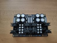
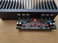
For Sale DCG3 + DCSTB fully built and working

Since I decided at the last stage for another preamplifier, I am forced to sell this one. It's definitely a great preamp but for capacity reasons I'm forced to sell it.

The preamplifier has a set bias voltage of 170mA, ideal for low-ohm headphone. All parts are genuine from @Tea-Bag

Sold only together DCG3+DCSTB. (Price is negotiable.)

Additional parts I can offer:
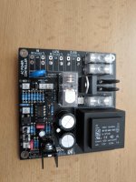
  • inteligent on/off module
  • Large heatsinks with pre-drilled holes.
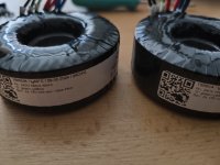
  • 2 pcs toroidal transformers from (toroidy.pl), 50VA, 240V, 2x18V
  • Khozmo attenuator 25K
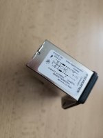
  • AC Power Entry Modules Shurter
I only send within the EU. (paypal, wire transfer)

I can give a discount when you buy all parts.

Attachments

  • IMG_20240721_124008.jpg
    IMG_20240721_124008.jpg
    318 KB · Views: 138
  • IMG_20240721_124023.jpg
    IMG_20240721_124023.jpg
    385 KB · Views: 131
  • IMG_20240721_124049.jpg
    IMG_20240721_124049.jpg
    249.8 KB · Views: 136
  • IMG_20240721_124109.jpg
    IMG_20240721_124109.jpg
    376.9 KB · Views: 128
  • IMG_20240721_124133.jpg
    IMG_20240721_124133.jpg
    163.8 KB · Views: 131
  • IMG_20240721_124148.jpg
    IMG_20240721_124148.jpg
    280.2 KB · Views: 132
  • Like
Reactions: passive420

So I was looking at Aliexpress for something else and I came across an IRS2092 implementation with balanced connection?

I had a look at the IRS12092 datasheet it seems to me there's only 1 input.

Also the amp seems to use 2 opamps to convert unbalanced to balanced (or maybe I misread the PCB labels and that it converts balanced to unbalanced). thoughts? Thank you.

https://www.aliexpress.com/i/32884021133.html

Speaker building parts/tools in carry on luggage

I’m visiting a friend and his boys…they are in the early stages of building a speaker…it’s their first one and they don’t have hardly any tools.

I have a twenty year carry on luggage only streak I don’t want to break and would like to bring the following with me….any problems?

Mylar dome tweeter
Speaker wire
Speaker terminals
Aux extension (3ft)
Aux to RCA
Wire stripper and crimper
Soldering iron and solder

The ones I’d think they might have issue with are the soldering iron and the wire stripper/crimper….but please inform me if there are others…or if you’d think no problem with any of the above.

Hello from Wichita, KS

Hey guys,

Long time lurker here. I play around mostly with Altec speaker stuff, but I do a reasonable amount of DIY audio things. I'm glad to be part of this community and the wealth of knowledge that is here. I'm a graphic designer by trade, so I worry more about the aesthetics then I probably should on my projects... but it comes with the job.

Thanks for having me.

- Woody

Citation II - 2023

Attached is my attempt at updating my Harmon Kardon Citation II amplifier to a PCB version.

It took me 7 versions,and a learning curve to understand the schematic & pcb software.
A friend of mine said that I should sell it as a kit, but I'm too old, 71 and I don't have all of the knowledge required to do so.
I do have a BOM built, and have determined that the cost to do this amp is about $650 for parts , minus tubes. KT88 cost about $400 for 4. The 12BY7A tubes price varies depending on where you buy them.
I'm curious if you or anybody else might be interested in my project.

If you are interested, please feel free to contact me.
Thank you for looking at my project.
  • Like
Reactions: OtisCampbell

NAD D 3045 sonic blast, max db out

Today after 10 minutes of operation the NAD 3045 internal digital went amok resulting in a rapid rise to max volume. I rushed to turn it down and pull the AC cord which I will not connect again. In future, I will avoid integrated computerized amps because they have more failure modes with less reliability than classic amps or chip amps. I am upgrading an old (vintage?) NAD 320 to replace the 3045.

I dislike multi-turn volume controls because they compromise usability.

history: https://www.diyaudio.com/community/threads/nad-d-3045-overheating-allegedly.379438/

Weirdness with Benz Genz Shuttle 6.0

Help diagnosing Shuttle 6 Pre-Amp

Help Diagnosing Shuttle 6 Pre-Amp

I resoldered the major caps, all of the solder joints on the vacuum tube pcb, and the input and output ports. That doesn’t seem to have fixed the clipping, but the output did have a hole in the solder joint, which could be an issue, and I cleaned up some crappy solder joints on the vacuum tube pcb with holes too.

It could be an EQ thing where it’s just not going to sound right unless you play with a bass since it’s optimized for lower frequencies - that’s my main thesis as of right now. I do notice playing all higher notes on the bottom three strings the noise fades away really fast or clips, as does the same thing on the entire upper side of the fretboard so I think this one is likely.

If you keep the gain all the way up and volume low you can make playing with a guitar sound bearable, but it will clip on the highs and you will get that background distortion/rumble behind it no matter what, to varying degrees - mostly when hitting multiple strings and on long notes the sustain doesn’t seem right, but again, maybe EQ is to blame.

It’s also way too loud to be pleasant through the headphones unless you turn down the volume via the headphones themselves, I find that odd.

I do notice the input signal seems to be off, like I mentioned the his will cut off; the lows do too at at a lesser rate - but it will come in and out during long sustain notes, cutting off slightly early it seems. Not sure if it’s an EQ thing as mentioned.

I noticed some oddities with the input signal by listening and watching the light. The input light flickers as the sound cuts off - which could indicate a bad port input port, if, again, it’s not an EQ thing.

So perhaps it could be fixed with a new input port?

Attachments

  • IMG_1546.jpeg
    IMG_1546.jpeg
    401.9 KB · Views: 79

wparks from Lewiston Idaho Checking In

Howdy-

Apparently I'm not allowed to post anything until I introduce myself, so here goes.

I'm wparks from Lewiston, northern Idaho. Lewiston is a small town at the confluence of the Snake and Clearwater rivers, an actual ocean-going sea port way over here in the Idaho panhandle. We're at 700 feet elevation and deep down in a large valley so the weather is extremely mild. I'm a retired electrical engineer who specialized in microprocessor design and validation for HP and Intel until I burned out, sold everything, and ran to the off-grid lifestyle in the rural countryside. Best move =ever=.

Now that I know what I want to be when I grow up I'm moving into more discrete electronics. I cut my teeth on monochrome monitors before the internet was even a thing, so getting to learn about all of the newest technologies available now to the amateur hobbyist has been very empowering. I have a growing passion for high quality audio, and have begun learning, assembling and experimenting with my hi-fi gear. I am limiting myself to a low budget, building for myself as much as possible, and maximizing fun and experience rather than making some blind jump right at "end game" equipment- crawling before running and all that.

Music that is flowing in my veins: mainlining Portishead, freebasing Tool and more Tool, snorting Black Sabbath, smoking Pink Floyd, and popping Gorillaz

Some gear I own and am learning/having fun with:
Sony SSCS5 speakers - my favorite starter speakers and best sounding I have ever owned (so far . . .)
Philips SHP-9500 Headphones - Inherited from my father and discovered on my own just how sweet they are- Thanks Pop!
1961 Magnavox 9302 15Watt 6BQ5 tube amp - A $40 console pull I reworked into an audiophile contender with Dave Gillespie's mods from Audiokarma
1978 Magnavox R344 12W white trash transistor chassis from a $20 console I turned into a pretty stand-alone wooden cabinet integrated reciever
Denon DCD-1500ii CD player - my only piece of audiophile pedigree bought for $10 from an estate sale that just needed new tray belts (knowledge =IS= power)

Recent projects I have built or are building:
"Combat Audio" +/- 15V 1.5A regulated power supply in an army surplus ammo can for powering all of my diy audio gear
Phono Preamp based upon Rod Elliott's ESP project 06 Hi-Fi Phono Preamp that is the best sounding I have heard (comparing across 4 others)
Most excellent headphone amplifier based upon Rod Elliott's ESP Project 113 that drives my 32 Ohm cans to tantric ecstasy. Oh so good!
Modifying a several crappy Fisher "Studio Standard" 🤣 (B.P.C. era) amplifiers into something somewhat respectable
Repairing and cleaning junked stereos and boom-boxes for dontation to local charities
Crappy Acoustic Monitor PSM-1250 12" 3-way retro design tower speakers I am gutting and redesigning into something respectable.


I have learned an incredible amount about electronics design as supported by my education, and a lot about what makes good audio. I have a voratious appetite for new knowledge, and I love to teach what I have learned. I'm here to listen, learn, and teach when I can. Looks like a fun group.

-Warren

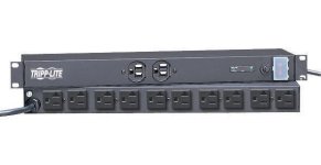
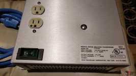
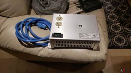
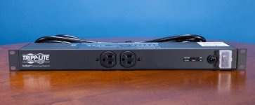
For Sale DALE Isolation Transformers & 19" ISOBAR Power Bar

have for sale:

2 (qty) DALE IT800 - Isolation Transformers (Medical Grade <100uA leakage)
Each unit contains an actual 900VA nominal rated Toroidal Transformer
Capacity - 6 Amps input
Capacity - 5.7 Amps Output
Hospital-Grade Power cord with 2 receptacles (Green Dot)
I used one for Analog sources and the other for digital sources to enable total isolation of digital " noise" getting into the analog system

$129.00 USD each with Free Shipping to US & Canada
Take BOTH for $199 USD with Free Shipping to US & Canada

ISOBAR 12 ULTRA 12-Outlet Power Bar - 19" Rack mountable,
15 ft. (4.57 m) Cord,
3840 Joules, Diagnostic LEDs,
1U Rackmount
NOTE: I used Stock pics for the ISOBAR

$99 USD with Free Shipping to US & Canada

Attachments

  • 01F2187-40.jpg
    01F2187-40.jpg
    14.1 KB · Views: 83
  • 2512788-96e3f091-lot-of-partsmeasuring-toolscaps-amp-many-other-items-available.jpg
    2512788-96e3f091-lot-of-partsmeasuring-toolscaps-amp-many-other-items-available.jpg
    107.5 KB · Views: 76
  • 2512789-3d0baa9b-lot-of-partsmeasuring-toolscaps-amp-many-other-items-available.jpg
    2512789-3d0baa9b-lot-of-partsmeasuring-toolscaps-amp-many-other-items-available.jpg
    109.3 KB · Views: 81
  • Tripp-Lite-ISOBAR12ULTRA-Front.jpg
    Tripp-Lite-ISOBAR12ULTRA-Front.jpg
    31.5 KB · Views: 80
  • Tripp-Lite-ISOBAR12ULTRA-Internal-1.jpg
    Tripp-Lite-ISOBAR12ULTRA-Internal-1.jpg
    89.9 KB · Views: 76

Yet another crossfeed...

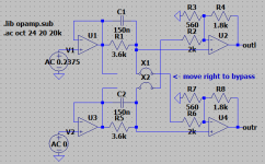
It all started when I decided, just to be a contrarian, to do a hardware simulation of a plugin, ha! I've used 112dB's Redline Monitor for mixing since it came out some fifteen years ago, and I'm sure there are better crossfeed solutions out there, both software and hardware, but it's what I like and am used to, so I thought, why not see if I can make an actual circuit that does the same thing.

Although I've never seen this topology and I arrived at it after lots of trial and error, I'd be surprised if it hasn't been done before, in fact I would assume that the plugin developers based their code on some existing circuit or other, which could be this one or something very similar... In any case, I was delighted that I could pretty much nail the plugin's response with such a simple circuit. So far I've only tested it using LTSpice's awesome WAV processing feature and, although it doesn't null perfectly with the plugin, it's more than close enough and I doubt I'd be able to tell them apart in a blind test.

The plugin has three parameters to adjust: a "center level", which adjusts the phantom center from 0 to -3 dB, a "soundstage", with selects the simulated angle between monitors from 30 to 90 degrees, and a self-explanatory "distance" from 0 to 2m. After some experimentation, I settled on, respectively, -1.5dB, 60 degrees and 0m (any other distance introduces FR ripples that I don't care for), so that's how I've always used it and what I've attempted to implement. In the first picture below you can see the left and right response when only the left channel is active, both as shown by Plugin Doctor and as simulated in LTSpice (I don't show the phase responses but they aso match). See also the schematic and two LTSpice circuits, the AC simulation and the WAV processing simulation.

I'll have more to say about component value selection, gain, opamp choice, etc. if there's interest, but in the meantime you can feed it your own WAV file and see how you like it, just change the file name in the voltage sources and place it in the same folder as the .asc file. Note that, as well as attenuating the output by the inverse of the gain, I knock off another 3dB to prevent clipping, which will happen if your WAV goes to full scale, so adjust accordingly when comparing the before and after. You can also adjust the duration in the .tran statement for the output file length (in seconds) you want. Anyway, have fun and let me know what you think!

Edit: typo in the schematic, it should say "move left to bypass"...

Attachments

  • Cabi-XFeed-FR.png
    Cabi-XFeed-FR.png
    63.4 KB · Views: 301
  • Cabi-XFeed-sch.png
    Cabi-XFeed-sch.png
    8.7 KB · Views: 303
  • Cabi-XFeed.asc
    Cabi-XFeed.asc
    3.1 KB · Views: 94
  • Cabi-XFeed-wav.asc
    Cabi-XFeed-wav.asc
    2.8 KB · Views: 124
  • Like
Reactions: jasonRF

Corner loading PA sub test and OMG

Guys,

Yesterday I DJied in a club
That I use to play sometimes

Humble old system below
2 Yorkies LS608's driven by a bridged XLS 2500 and a pair of yammies DSR12's

Although the Yorkies run out of gas before the yammies I balance the system so it sound even.

Anyway ...
I followed the place subs on center of the floor

Yeah normal sound
Coming from the system config.

So it occured to me recalling many reads that says if you face the subs to a corner it will "amplify" the sound ....

I just tested that that I have seen many years ... Never tried , I don't know , is just something that you think will not do much.

OMG!!
It sounded like 4 or even 8 ...cabs
(Never tested multiples next to each other)
So can't tell really but for sure sounded double or triple the volume.

Same cab count ..same single amp
The owner jAW dropped , he thought I bring more stuff and he can't locate the subs as they were not in the center !! Lol

I know that can't be done on some places
But if you can do it..DO it!!!

I will post some pics with some length measurements.
The ceiling is pretty high.

The bass covered the whole dance floor and even another section were another DJ was playing lol.

It was effin incredible....really
How it never occurred to me to actually do it
It was like ....nahh not noticeable or very little gains....nope...totally wrong
It was hugeeee.. improvement !!

And the clients were amazed
They told me ..wow new system sound incredible. Lol!!

Women never have nuff shuz...
Men never have nuff bazz!!

Balanced line amp - 1 noisy output

Hello,

I’ve build a clone Blowtorch line amp. See picture of build and circuit below.

As I’m busy with the actual assembly of the PCB’s on a bottom plate from the enclosure, I was testing with different wiring layouts and wires itself (twisted solid core and microphone coax).

During this testing I noticed that one of the 2 balanced line amps generates a Hiss / white noise on the ‘+Out = OUT_P’ output. Taking the signal from ‘-Out = OUT_M‘ gives no noise. Noise sounds like: Analoge ruis - Ambient Reel to Reel Bandrecorder Hiss & Hum - YouTube


I don’t have the knowledge to tell whether a Jfet or a mosfet can generate this as a failure mode due to a static decharge for example. And before I start to remove and change parts, I would like to ask here for experience.

Which part is highest change to resolve this noise issue?


Thanks in advance

Attachments

  • IMG_2656.jpg
    IMG_2656.jpg
    540.6 KB · Views: 298
  • As build.JPG
    As build.JPG
    69.9 KB · Views: 305
  • Like
Reactions: Mikerodrig27

Understanding the use of inductors in bandpass subwoofers

Understanding the use of inductors in bandpass subwoofers and impedance curves.
I've had two small bandpass subs (neither impressed me). One used a capacitor on the pass-through, a rudimentary high-pass filter to the main speakers. The other uses an inductor, a low-pass filter to the drivers.
I always believed bandpass subs didn't need filters, so I assume the inductor's purpose is related to impedance.

This brings me to the impedance curve of the setup. How many peaks would there be?
1 at the resonant frequency of sub driver.
1 at frequency sub's port.
1 at the resonant frequency of the satellite's woofer.
1 at the resonant frequency of the satellite's port.

Is that right?

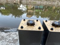
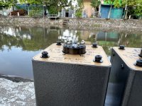
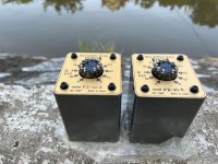
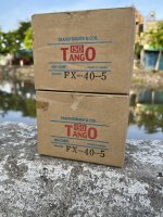
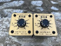
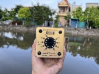
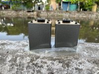
For Sale Iso Tango FX 40-5

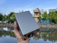
I need to sell 1 pair of Tango FX 40-5 audio output transformers, which I keep in storage unused.
perfect used condition.
desired price 420$
I live in Ho Chi Minh city

Attachments

  • IMG_0255.jpeg
    IMG_0255.jpeg
    521.3 KB · Views: 196
  • IMG_0254.jpeg
    IMG_0254.jpeg
    571.9 KB · Views: 191
  • IMG_0253.jpeg
    IMG_0253.jpeg
    582.7 KB · Views: 145
  • IMG_0252.jpeg
    IMG_0252.jpeg
    412 KB · Views: 164
  • IMG_0238.jpeg
    IMG_0238.jpeg
    699.9 KB · Views: 160
  • IMG_0242.jpeg
    IMG_0242.jpeg
    442.6 KB · Views: 157
  • IMG_0243.jpeg
    IMG_0243.jpeg
    253.2 KB · Views: 156
  • IMG_0244.jpeg
    IMG_0244.jpeg
    288.7 KB · Views: 141
  • IMG_0246.jpeg
    IMG_0246.jpeg
    290.9 KB · Views: 151
  • IMG_0248.jpeg
    IMG_0248.jpeg
    291.8 KB · Views: 152
  • IMG_0249.jpeg
    IMG_0249.jpeg
    289.7 KB · Views: 149
  • IMG_0250.jpeg
    IMG_0250.jpeg
    709.9 KB · Views: 144
  • IMG_0251.jpeg
    IMG_0251.jpeg
    477.2 KB · Views: 213

For Sale Allen-Bradley Type J Stereo Potentiometers, Alps Black Beauty, and other assorted goodies

Hi All

Item #1: SOLD

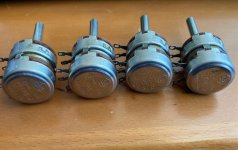
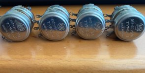
ALLEN-BRADLEY Type J dual potentiometer
, audio taper. These are original, all-sealed and pretty rare. 2Meg.

I have four pieces. One has some solder on the eyelets from some testing. You will see they all have nice long solid shafts. They don't make them like this anymore.
IMG_0216.jpgIMG_0217.jpgIMG_0218.jpg

Price: CHF 20.- each OR the whole lot for CHF 60.- plus shipping.

Item #2: SOLD

ALPS BLACK BEAUTY stereo potentiometer
(stepped) from Japan up for grabs. This is the real deal- Vintage, straight out of the late 60's or 70's. It was used in Macintosh, Luxman and other great amplifiers of the day. 250k. This is not the cheaper small ALPS pots you find on ebay. Beautiful movement. Slightly soldered eyelets and back paper label a bit aged.
IMG_0228.jpgIMG_0229.jpgIMG_0230.jpg

Price: CHF 80.- plus shipping.

Item #3: STILL AVAILABLE

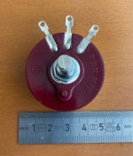
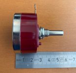
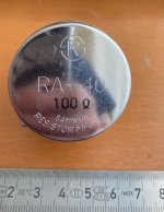
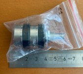
SAMWHA RA-40
wire-wound 100 Ohm precision potentiometers. These are NOS and are superb quality. I used these many times for cathode bias duty. Sadly they are no longer available since some time.
IMG_0225.jpgIMG_0226.jpgIMG_0227.jpg

Price: CHF 15.- each, plus shipping. All 4 pieces for CHF 50.-

Item #4: SOLD

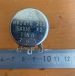
TOKOS Cosmos RV24YG 20S 100k stereo potentiometers
. These are really decent quality stereo potentiometers - made in Japan. However, they have a very poor reputation for channel matching. It's like a lottery buying them. Some years ago I bought a BIG LOT of them and took the time to sort out the (very few) GOOD ones that happened to be decently matched. Often I would find only 1 or 2 our of every 10 pieces which matched decently enough.

IMG_0223.jpgIMG_0224.jpg * note some of these may have light solder on the contacts, only from testing.

I can sell a few of these in two varieties:

Select 2: Channel matching 2% or less. Price: CHF 25 each, plus shipping
Select 1: Channel matching 1% or less. Price: CHF 50 each, plus shipping


Free Stuff: ALL GONE NOW

If anyone wants some new, never used Tocos Cosmos RV24YG 20S 100k stereo potentiometers that don't match as well as the ones above, message me. You just pay for shipping. Update: 30 June 2023 - all gone now.


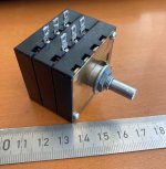
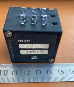
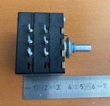
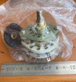
Also - I have two, 4 channel, 5 position USSR input selectors.

IMG_0221.jpgIMG_0222.jpg

These have silver connectors. They are break-before-make and even come with a very nice vintage Bakelite knob. Never used. You just pay the shipping. Update 26 June 2023 - all gone now.

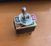
AND - If you want a nice decent Power Toggle switch with on/off label, message me. These ones I have from Toowei are from China and quite decent.
IMG_0219.jpgIMG_0220.jpg
I have at least 5 of these that someone can have for free. You just pay the shipping. Update 30 June 2023 - all gone now.


Note: Buyers who might want the free stuff get first dibs.

Shipping is from Switzerland, and swiss post is not cheap... but it goes by weight, and I will only charge you what I pay.

Ian

Bedini amp repair advice

I'm hoping someone can point me in the right direction to repair my Bedini 100/100 amp. I build speakers. Amps are a mystery to me. I know I can't fix this myself unless it's a basic item. the amp has been in storage for years. It worked when it was put away. Now only the left channel works. This is a class A amp. The right channel doesn't even get warm like it should. I checked all the fuses. They all look and test fine. Is there anything else a novice can check to see why the right channel isn't powered up?
If not, is there anyone who works on these old amps? The Bedini brothers both have passed away. I'd like to get this amp back in service. I have a Bedini 25/25 DE that I'd like to use with the 100 to bi-amp. Any information is appreciated.

Hello from Slovenia

I'm reading this forum since years and posting a little but and now starting some repairs and i can see some real experts here 🙂

I'm Zoran from Slovenia, almost 50 years old and I'm repairing , building electronic in my free time since for ever i think ha ha.

Usuly some DAC or music servers , repairs of amps and Audio gear in general.

Hope i can find some ideas, tips and knowledge in next level of my journey 🙂

Greetings

Zoran

For Sale Thales Easy Tonearm

I purchased this Tonearm in April 2022, so it still has warranty to 04/23.
It was ~1 year in use. It just came back from the manufacturer where a check up was made.
Condition is absolutely as new. Comes with the complete & original accesories and boxing.
Shipping overseas is possible but checking customs conditions is up to the buyer.

Asking for 3500€ + shipping.

Thales Easy

20231209_134055.jpg


20231209_134119.jpg


20231209_134138.jpg


20231209_134142.jpg


20231209_134146.jpg


20231209_134148.jpg


20231209_134214.jpg

Help, value of Lundahl SRxxx transformers

I have been cleaning a bit and found a box of old lundahl transformers. Are these still interesting and what is an appropriate value to sell these for?

8 pcs SR501
3 pcs SR502
17 pcs SR503
2 pcs SR504

P_20240822_124222.jpg


Information from lundahl website:
https://www.lundahltransformers.com/faq/
  • SR501 is a high level 600 ohm : 600 ohm isolation transformer.
    • in+ 1
    • in- 5
    • out+ 7
    • out- 9
    • Faraday shields 6+10
  • SR502 is a high impedance bridging input transformer.
    • in+ 1
    • in- 5
    • in centertap 3
    • out+ 7
    • out- 9
    • Faraday shields 6+10
  • SR503 is a line output transformer with turns ratio 1.4 : 1.
    • in+ 8
    • in- 6
    • out+ 10
    • out- 4
  • SR504A is a microphone transformer 200 ohm : 2k
    • 1 2 3 4
    • SR504
    • 5 6 7 8

    • SR504 /SR504A PCB Flying leads
    • in+ 2 red
    • in- 3 yellow
    • out+ 6 green
    • out- 7 grey
    • core 1
    • housing 4
    • Faraday shield 5+8 black
    • SR504a is similar to the more modern transformer LL1538

Failed CD laser repair - point me in the right direction?

I have an Audio Research CDT1 (https://www.arcdb.ws/model/CD1). It has occasional errors reading disks, and skips on disks that work fine in other players. I decided to replace the laser, and ordered one from Some Guy On eBay(TM). The replacement went smoothly enough, but on test the player always reports "no disk". The CD doesn't even spin up, the laser mechanism moves the head up and down a few times, then gives up.

I had this issue on a Rega CD player I replaced lasers on, but it was just that I hadn't cleared the ESD protection solder blob. I can't spot a similar blob on this unit.

I've emailed the seller to ask for advice. In the mean time, I wondered if you fine folks might have any suggestions I hadn't thought of. The spinner motor is not being sent power from the board, I checked with a meter, so it's not that the motor failed. I haven't tried reinstalling the old laser, because it's kind of a pain in the ***. I have contacted Audio Research about getting a proper laser, which they have, but apparently they are so behind on orders they can't take my money yet. So, that is on hold.

Capacitor voltage needs ?

I am new to valves, So obviously I do not understand them.
Having said that, I have been handed a preamp to 'update' (yes some of the parts really do need replacement due to eminent failure).
I believe it is capable of 12v output.

My questions are in regards to c2 3uf/200v film cap.

What voltage does it actually need to handle ?
How much frequency response change would it cause if it was changed to a 2.7uf or 3.3uf ?

Thanks 🙂

valve pre.jpg

Aksa Lender P-MOS Hybrid Aleph (ALPHA) Amplifier

Following in the footsteps of the Aksa Lender preamp, Hugh and I have been working on a Class A power amp that uses the Aksa Lender front end. We wanted a SE Class A amp with more efficiency than a simple CCS so we decided to try using the very nice Pass Aleph (dynamic bias) CCS. Hugh is using a P-MOSFET as the lower output device, so this is sort of a hybrid, modified Aleph. It is a very simple 6 active amp with no fancy unobtanium JFETs, SITs, hockey pucks, power JFETs, fairy dust Sony FETs, or signal transformers. If you look at the prototype built on veroboard, you will see the usual low cost stuff. The fanciest part I have is a 10uF Silmic II input cap. The rest of the caps are budget Aliexpress. I like to proto with cheap parts, that way there is less pressure in case it flops 🙂 I am using genuine Vishay IRFP's from Mouser though.

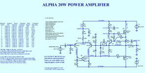
Here is the basic circuit and predicted performance specs (it's good for about 20w with 24v rails):
659376d1517198709-aksa-lender-mos-hybrid-aleph-alpha-amplifier-alpha-20w-pchan-schematic-png


The circuit uses Hugh's Aksa Lender preamp front end with an Aleph CCS on the top, and a P-channel MOSFET on the bottom driven directly from the Aksa Lender LTP. No CCS on the LTP needed.

Hugh also worked on a monster version of this amp with +/-35v rails and 150w of dissipation per channel to make 53wrms into 8ohm before clipping. To get things rolling, I opted for the +/-24v rail version at a more modest bias of 1.2amps. Slowly work my way up in bias current and then maybe rail voltage (with bigger output devices).

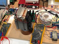
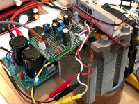
So here is the prototype on a tiny 5cm x 7cm veroboard with two MOSFETs hanging off one end right next to each other. Why so close together? I wanted to use a computer CPU heatsink with heatpipes to cool them - in anticipation of 140w later on. This amp was particularly difficult for me to get running because I made so many wiring errors (a problem when you build it in the wee hours of the morning after a full day of work). Once I found all my errors, the amp fired up no problem. I matched the beta's of the input LTP KSA992's and got perfect 0mV DC offset with no trimpot. You will notice that the tiny (relatively speaking for a Class A) hetsink is fan cooled and has lots of heat pipes (which normally work flipped the other way unless they have capillary wicking inside). But I found them quite effective upside down even as temp was 31C with 55w dissipation. These are salvaged Dell heatsinks for workstation, about $12 to $15. For the record, I am using 1000uF 35v on C3, 22pF NP0 on C4 and C9, and 4x2.2nF (8.8nF) MKT film on C7, 0.47R on R17 and 0.15R on R18. I also have an input RFI filter consisting of 2k2 in series before C1 and a 220pF MKT cap to GND, and 100uF 63v on C2. On C5 and C6 I am using 220uF 100v caps. i had a nice 220uF Silmic II but it was too big to keep on the board and still let me see the resistors unerneath when I was debugging. Otherwise, parts are used as shown on schematic.
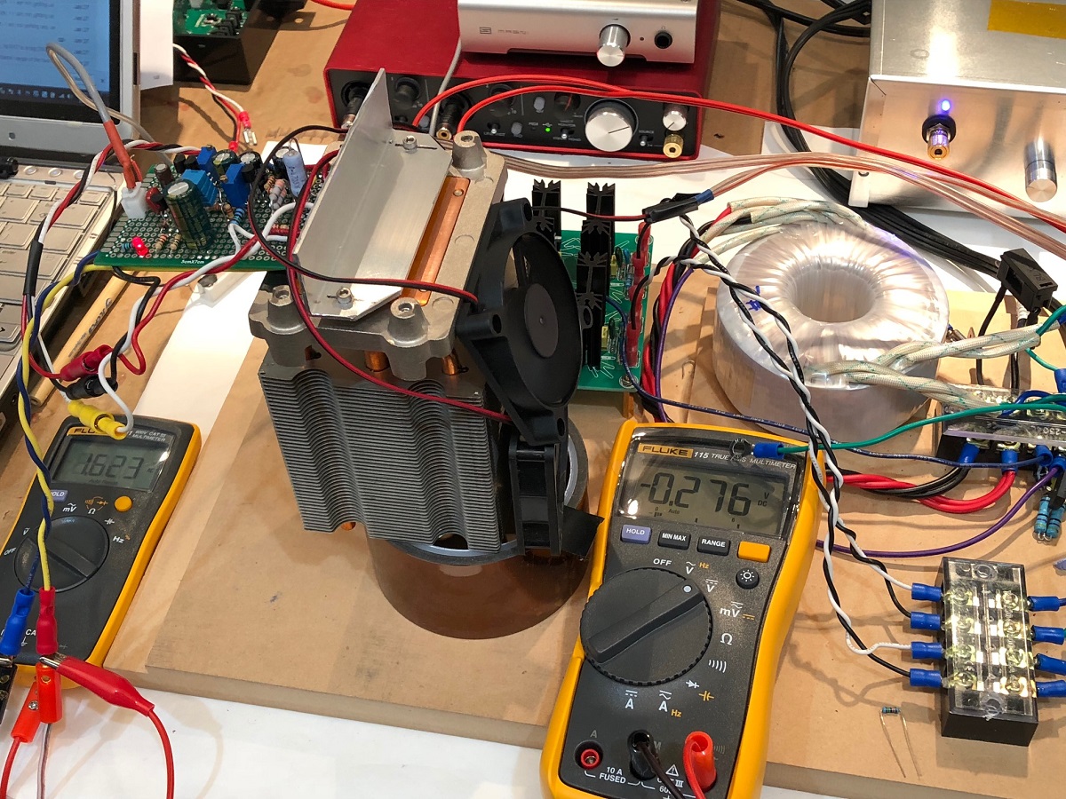
659377d1517198709-aksa-lender-mos-hybrid-aleph-alpha-amplifier-alpha-prototype-01-jpg


Closeup of the amp:
659378d1517198709-aksa-lender-mos-hybrid-aleph-alpha-amplifier-alpha-prototype-02-jpg


Without heatsinks (I eventually removed the Silmic II 220uF 50v Aleph feedback cap to make room for debugging):
659473d1517249318-aksa-lender-mos-hybrid-aleph-alpha-amplifier-alpha-20w-prototype-bare-jpg


Listened to it for a few tracks and must say, it sounds quite nice and engaging. I know the sound. Foot tapping good - typical Hugh Dean style amp. 😀

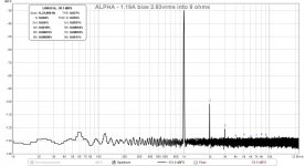
So here is the first measurement of this simple unassuming amp that takes the best of all worlds. 1kHz 2.83vrms into 8ohms and we get 0.027%THD but in typical Aksa style, mostly in second harmonic, and 10x less in third harmonic, and not much else. This is running well below the recommended 2.0amp bias. So I expect the THD to drop. But the noise floor looks great - actually very good for a linear PSU - perhaps the best I have I seen for one of my linear PSU amps. I am using a basic 100VA donut with 18VAC and a Project16/Prasi CRC PSU with 22mF caps all around and 0.235R on the CRC.
659379d1517198709-aksa-lender-mos-hybrid-aleph-alpha-amplifier-alpha-1-19amp-2-83vrms-8ohms-fft-jpg


I will try boosting the bias current next, and then maybe try to go for the monster 53wrms amp with 35v rails 🙂

Hope you enjoy it - and if enough interest, JPS64 can design a splendid PCB for us to use. Thanks to Hugh for another gem to the DIYA community. And thank you to Mr Pass for the wonderful Aleph CCS.

Here is the latest Schematic for the Big Boy 52W version - now at a little under 3amps bias and 90W dissipation per side, still need two CPU coolers per channel.

660208d1517584966-aksa-lender-mos-hybrid-aleph-alpha-amplifier-fciehdohbfnkegdm-png


Edit Feb 11, 2018: the Alpha 20 PCB is finally built and tested.
661735d1518324741-aksa-lender-mos-hybrid-aleph-alpha-amplifier-alpha20-amp-build-02-left-jpg


It measures very well here with 1.31amps bias and produces 0.0069%THD for 2.86vrms into 8ohms:
661737d1518324741-aksa-lender-mos-hybrid-aleph-alpha-amplifier-alpha-20-2-87vrms-8ohms-fft-png


ALPHA 20W schematics and stuffing guide for v4 (production boards) here:
Aksa Lender P-mos Hybrid Aleph (ALPHA) Amplifier - Page 12 - diyAudio

660029d1517503984-aksa-lender-mos-hybrid-aleph-alpha-amplifier-alpha-20w_schematic-v4-png


660032d1517503984-aksa-lender-mos-hybrid-aleph-alpha-amplifier-alpha-20w_topview-png


660030d1517503984-aksa-lender-mos-hybrid-aleph-alpha-amplifier-alpha-20w_3d_render-png


Edit Feb 20, 2018:
BOM v1 for ALPHA 20W PCB layout v4 (above schematic) here:
Aksa Lender P-mos Hybrid Aleph (ALPHA) Amplifier - Page 51 - diyAudio

Edit Mar 5, 2018: premium components build ALPHA20:
666395d1520249706-aksa-lender-mos-hybrid-aleph-alpha-amplifier-alpha-premium-build-02-jpg


It does indeed eek out a bit lower distortion with Vishay Dale resistors and all Wima and Silmic caps, now about under 0.006%THD for 2.75vrms into 8ohms:
666397d1520249706-aksa-lender-mos-hybrid-aleph-alpha-amplifier-alpha-ch2-fft-png


Edit March 25, 2018 - Alpha 20 for 4ohm loads version:
Aksa Lender P-mos Hybrid Aleph (ALPHA) Amplifier - Page 124 - diyAudio

Ignore the triple outputs - purely used to simulate a single larger 500W capable IXYS MOSFET pair which will not need to be matched. Hugh does not recommend using triple output IRFP’s

669823d1521533665-aksa-lender-mos-hybrid-aleph-alpha-amplifier-alpha4r-gif


Edit April 4, 2018: BigBoy is alive and singing! The Beta build went together almost perfectly. Only one minor circuit error on the grounding of the LTP smoothing cap (fixed with a jumper). Amp starts up uneventfully and without any adjustment to achieve 3.0amps bias current and 1mV DC offset.

672472d1522616478-aksa-lender-mos-hybrid-aleph-alpha-amplifier-alpha-bb-test-mono-fast-closeup-jpg


Here is 34wrms into 8ohms from +/-27.6v rails:
672327d1522552973-aksa-lender-mos-hybrid-aleph-alpha-amplifier-alpha-bb-sound-oscope-02-jpg


Here is FFT at 2.84vrms into 8ohms:
672545d1522650414-aksa-lender-mos-hybrid-aleph-alpha-amplifier-alpha-bb-no1-2-95amp-2-84vrms-80hms-fft-jpg


Edit April 4, 2018 - here is the updated as-built schematic for Alpha 20 with 1.35amp bias and no turn-on thump feature. Note that if all pots are removed the amp is a simple adjustment-free Class A amp with DC coupled output that has DC offset within 10mV (typical) and self-tracking, bias current is auto-regulated and very stable:
673097d1522861468-aksa-lender-mos-hybrid-aleph-alpha-amplifier-alpha-20-schematic-updates-1-35amps-built-png


Edit April 7, 2018: Alpha B.B. in stereo!
673651d1523088129-aksa-lender-mos-hybrid-aleph-alpha-amplifier-alpha-bb-stereo-build-04-jpg


FFT of Alpha BB at 2.85vrms into 8ohms
673787d1523165499-aksa-lender-mos-hybrid-aleph-alpha-amplifier-alpha-bb-2-854vrms-8ohms-fft-ch1-jpg


Edit April 10, 2018: Summary of various settings to change amplifier configuration bias setpoinysnand speaker impedance driving capabilities. Courtesy of Danny_66: Aksa Lender P-mos Hybrid Aleph (ALPHA) Amplifier - Page 166 - diyAudio

Edit April 13, 2018: Simulation LTSpice files of Alpha 20 4R and 8R by Danny_66 here:
http://www.diyaudio.com/forums/soli...id-aleph-alpha-amplifier-172.html#post5404051

Edit April 19, 2018: 10kHz 17vpp square wave into 8ohms on Alpha BB:
675635d1523938773-aksa-lender-mos-hybrid-aleph-alpha-amplifier-alpha-bb-5mhz-osc-study-10khz-square-wave-jpg


Edit Aug 23, 2018: several people have contacted me about ramping up for a new build. So here is a recap of suggested schematic for a 4ohm Alpha 20 (which probably puts out closer to 35w into 4ohms):
674314d1523391739-aksa-lender-mos-hybrid-aleph-alpha-amplifier-alpha-20-schematic-updates-2-4amps-4r-png


Edit Sept 4, 2018: Tips for 4R capable circuit...
Aksa Lender P-mos Hybrid Aleph (ALPHA) Amplifier

Edit June 11, 2019: revised table of source resistors for setting bias current in Alpha 20 for 8ohms and 4ohms by Danny66:
Aksa Lender P-mos Hybrid Aleph (ALPHA) Amplifier
Attachments

  • ALPHA-20W-Pchan-Schematic.png
    ALPHA-20W-Pchan-Schematic.png
    287.2 KB · Views: 25,264
  • ALPHA-Prototype-Working-01.jpg
    ALPHA-Prototype-Working-01.jpg
    450.6 KB · Views: 19,993
  • ALPHA-Prototype-Working-02.jpg
    ALPHA-Prototype-Working-02.jpg
    463.3 KB · Views: 22,421
  • Alpha-1.19amp-2.83vrms-8ohms-FFT.jpg
    Alpha-1.19amp-2.83vrms-8ohms-FFT.jpg
    146.1 KB · Views: 20,462

For Sale 4 Kubelic DACs including input boards $50 CAD

3 dac kits
3 spdif/coax input boards
1 usb input board
1 digital select switching board kit

1 complete and operational dac ready to use. I've ran this dac for a year or more off and on..

Dac Voltage is 20vdc

$50ca plus shipping for everything - canada and usa only

Attachments

  • thumbnail_20240818_110335.jpg
    thumbnail_20240818_110335.jpg
    770.9 KB · Views: 139
  • thumbnail_20240818_110342.jpg
    thumbnail_20240818_110342.jpg
    808.1 KB · Views: 138

Hammond tube based organ - finding a short

I have a Hammond S-6 organ I picked up; with limited knowledge I am trying to trouble shoot it - using a light bulb limiter to power up.

Here's where I'm at with it now:

When I detach secondaries from p/s, I see correct voltages on p/s. (B+ 310v, 6.3v, 25v)

When I detach just the 6.3v, I am seeing almost right voltages - like 240v/5.5/22 and the light bulb limiter glows only faintly. So I think there is a problem in there. The 6.3v reads about 0.8ohms across it so the meter reads "short" between them, but I think that's normal (?)

With secondaries attached, I see 0 on B+, 1.2v, and 8v.

With secondaries attached (limiter glows bright), When I start pulling tubes (it has 2x 6v6, a couple 12ax7, three 12BH7, and lot of 12au7s) the bulb limiter gets dimmer and the voltages go up from that low starting point. As expected, the 12BH7s pull the most current and make the most difference. With just a few tubes in there I see a little bit of glow on some of the tubes with about 4.5v on that secondary.

I'm not sure this tells me anything about the tubes per se. No one or combination of them solves anything in terms of just getting good 6.3v voltage.

I replaced one filter cap, tested the other and it seems okay. Any ideas what kind of failure this might indicate? Although there is a lot to the circuit, nothing looks blown out or short. Any insights appreciated.


HammondChordOrganServiceManual-ModelsSS1S4.pdf - Adobe Acrobat Reader (64-bit) 8_18_2024 2_45_...png

I'm from Hamburg, Germany

Hi,

I'm reading this forum since years but never answered a topic.

Ok, I'm Christian from Hamburg, Germany, 67 years old and I'm building amps since 53 years (with a gab from 30 to 45 years).

In the last years I started repairing (Dynacord, Echolette...) and building valve amps (Hiwatt DR405 clone, a 500W valveamp with 6x KT120 and Fender style preamp).

For this I'm looking for measuring equipment like interfaces and more to measure my amps.

Greetings

Christian

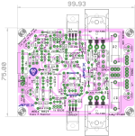
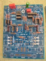
Apex AA14 Amp Class A 24V Supply

Hi
Next Project an the way 😉


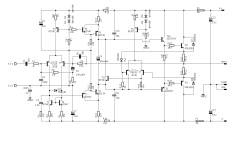
APEX AA14 - Class A amp...Prasi did excellent documentation. !! THX!
Gerber file : post #3

I want to try this amp but as i realized that nobody built this i want to ask in a separate Thread, because in the 100W Ultimate Fidelity Amplfier thread it is too mixed.

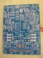
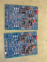
my build:
pcb in HASL standard quality - blue
because of try out some BJt transistor(BC557, KCS1845, ...etc....) and BD140...(3503/1381.....TTA...) i used pin header female - looks strange but...
As C1 i used a Nichicon Muse BP 10µF, As C4 i use a FKP2 Wima (FKP2G001001D00JSSD)

Don´t forget to wire an extra cable from GND signal input to the Power GND- its written on the top right corner on the bare PCB.

my question regarding caps.
because of avoiding some bad influence because of wrong caps - maybe too big capacitance i kindly ask:

C6, C9 are nichicon UKZ 100µF/25V UKZ
C3, C7, C12, C13, are 180µF/50V 105C Panasonic EEU-FR1H181L

Q1, Q2 :For the output transistor i plan 2cs5200 and SA1943
T14/T15 Driver MJE15028G NPN, MJE15029G PNP

help and comments are welcome .

thanks
chris

8.11.2023 edit: C4, - C6,C9 andC3,C7, C12, C13 updated

10.11.2023 edit: Driver T14/T15 correction, gerber file post#3

1.2.2024: edit: Amp is working with remove of D1
remove D1
change the value of R8 from 1k5 to 2k (2k2) - lower the gain to about 21dB
use a Thiele Network at the output (0,5µH //3R3 is working - Thiele Network

Attachments

  • AA14 lay-r5.png
    AA14 lay-r5.png
    71.9 KB · Views: 1,089
  • aa14 r5-bot cu.pdf
    aa14 r5-bot cu.pdf
    82.8 KB · Views: 210
  • aa14 r5-top silk.pdf
    aa14 r5-top silk.pdf
    64.4 KB · Views: 192
  • AA14 sch-r5.png
    AA14 sch-r5.png
    10.1 KB · Views: 1,131
  • Apex_AA14_amp_ClassA_1.jpeg
    Apex_AA14_amp_ClassA_1.jpeg
    354.2 KB · Views: 1,058
  • Apex_AA14_amp_ClassA_2.jpeg
    Apex_AA14_amp_ClassA_2.jpeg
    412.4 KB · Views: 594
  • Apex_AA14_amp_ClassA_3.jpeg
    Apex_AA14_amp_ClassA_3.jpeg
    483.5 KB · Views: 658
  • Like
Reactions: igniz

Installing the potentiometer at different points in tube output stage/preamplifier circuit

I have DAC with anode follower (voltage gain) tube output stage (2x 6N8S, 1/2 per channel). Now I want to install (other half of same 6N8S) a 2nd stage buffer (cathode follower) and potentiometer so I can directly drive tube power amp (with 6n6p at input). My question is where is a best solution to installi the potentiometer, either between the first and second stages or after the second stage?
Thanks.

Tube buffer for class D

Hi all, I'm interested in installing a tube buffer between my active pre and one of my amps, a class D. I have a two way horn system with an Azura that currently is driven by tubes from 600 HZ up, but I'm adding another small treble horn/CD and due to space constraints it's easier to add another class D module to an existing chassis rather than another tube amp to drive the small horn. Buuuut, I'd really like to inject some tube goodness here, but it's got to be balanced in and out. Can't find anything manufactured with bal inputs/outputs, so it looks like I'm going to have to build something.
Does anyone know of a kit or a good schematic for this? I could also build a pair of Nelson's H2 generators, I'm pretty sure I read somewhere they can be run with XLRs.

Any ideas or suggestions are very welcome, thank you.

Bryan

Fan of 3-way speakers and beyond

I came across the dome midrange thread and I thought this community would be a good place to ask a specific question about the dome mid in a pair of JSE speakers I got locally on FB. My first quality speakers were Vifa 3-way with the Vifa mid dome, dome tweeter and and 10 inch Vifa woofer, in a large ported enclose. The builder of the speakers replaced the dome mid because they didn't handle a lot of volume. The Vifa 6 1/2 cone sounded equally as good and didn't blow! That was in the late 80's and I still have the speakers to this day and they still sound great.

Fast forward to summer 2024. I have bought 2 pairs of speakers with dome midranges this summer. Infinity Kappa 8.1's, and JSE Model 2's. The Kappa dome mids are Simply Speaker replacements. I am now trying to find out which drivers are in the Model 2's. The tweeters are definitely replacements. The originals were Dynaudio 3/4 inch domes. Do the dome mids look like original 2 inch Dynaudio's? If they are, I believe everything is original except the tweeters which are now Morel I believe. The two bass drivers were re-coned around 10 years ago. Thanks in Advance for any help identifying any of these drivers and specifically the dome mid.
Infinite Slope speakers..jpg

A60-V1.0 vs. A60-V1.1

Earlier I had posted these questions to the wrong forum. My apologies, I am new at this.

Hi, first of all, credit to all the work that people have done on the A60 power amp "clones". I do have several questions:

1. Does anyone know the difference between the A60-V1.0 and the A60-V1.1 boards?
Note: A60 using 3x NPN and 3x PNP output stage version, not the 8x NPN and 8X PNP high power version.
I have looked high and low for this info and have had no luck to date.

2. Has anyone experimented with a revised VAS stage?
The A60 clone boards use an oddly revised cascode with bootstrap VAS stage vs. the Accuphase simple but effective cascode Darlington version.

3. Is there any good data on the THD vs. Po and frequency behavior of the A60 or the A60+ power amps?

4. Is there any concise discussion of mods or improvements to these boards?

5. Has anyone figured out the matrix of V60, V60+, V60++, and the various revs of these boards, V1.0, V1.1, etc?
It would really be nice if there was a central compilation of data and schematics for these assorted variants.

Thank you, and regards.

JBL 2404 driver substitute options

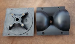
I have a set of JBL 2404 waveguide clones and wanted to explore possible viable options to use other drivers than the original alnico ring radiator JBL uses.

I've seen some drivers from BMS which happen to be ring radiators like the originals. The small 1/2" throat poses some challenges not being that common, but there's obviously a reason why JBL chose this size, for better top end extension.

This isn't really a big deal, but it would be nice to use this WG as a super tweeter for 3 way systems due to how nice it already sounds in stock phenolic version. There are some 1" versions of this WG, but its nothing close to the performance of the original.

Any takers?

Attachments

  • 20240815_111425.jpg
    20240815_111425.jpg
    442.8 KB · Views: 75

Behringer Xenyx preamp S.L.S. with single ended input

Hoping to use my small two mono channel Behringer mixer; one channel mic, the other guitar. Plugging the guitar signal in, sounds so distorted even my old iron ears can tell; literally a "splatter" type of distortion. Hoping to ride whatever the channel compressors can give me aesthetically, so turning down the signal isnt a solution, as that also removes the compressor drive. Mic channel using balance XLR seems fine. Putting the guitar through a DI box to convert to balanced seems to have a better sound.

Why would this be?

I mean it's not so bad; I have a solution. In other schematics I've seen they actually use a whole op-amp to invert the single ended input for the (-) signal internally; Behringer apparently "saved a whole op-amp" in their channel design, leaving it to the user to figure out why it sounds like crap. I also notice all the claims in their spec sheet for the channel are for the diff mic input; the SE specs do not follow the same claims for distortion 0.006% and dynamic range, 130 db. Which, outta do it.

Schematic:

1724181280568.png

New crossover for speaker with ribbon tweeter and dome midrange

Hi all - I have some speakers that I made almost 15 years ago which sound great, but only after some hefty EQ. At the time I was hesitant to make my own crossover due to lack of experience/knowledge so I got an off-the-shelf Dayton 3-way crossover (either 500/4K or 750/5.6K). It works, but because of the driver sensitivities/impedances the balance is pretty off.

Tweeter: Aurum Cantus G2si (6 ohm, 96dB) - with 2-3ohm resistor
Midrange: Morel MDM 55 (8 ohm, 90.5dB)
Woofer: Aurum Cantus AC250-F1 (8 ohm, 87dB)

I'd like to completely redo the crossover with values designed specifically for these. I've plugged the base values into a crossover calculator but I lack the knowhow to properly compensate for the mixed driver sensitivities, particularly the woofer. An L-pad I assume would work well for at least the tweeter while testing, but not sure if it would also work or be recommended for the midrange. These won't see particularly high power/volume as I don't listen super loud, but I don't want to risk damaging anything either.

Any thoughts on how to start with this? I do plan on continuing to use DSP, particularly for the low end, but at the very least I want to get everything as electrically aligned as possible first.

Thanks!

Polymer vs. Aluminum Electrolytic: Arguing with AI

So I have been arguing with AI on the pros/cons of switching from SMD electrolytic capacitors to SMD polymer on my computer PCIe USB card intended for audio and the benefits/drawbacks of each. It boils down to ripple current, but how much of a factor this plays considering the benefits of way better ESR and ripple from polymer - what is your take.

If we compare two caps:

Panasonic 16SVPG680M (Polymer)​

  • Capacitance: 680µF
  • Voltage Rating: 16V
  • ESR: 8mΩ
  • Ripple Current: 6.5A
  • Leakage Current: 2.176 mA
  • Temperature Range: -55°C to 105°C
  • Endurance: 5000 hours at 105°C
  • Package Type: SMD/SMT
  • Dimensions: Diameter 8mm, Length 11.9mm

Würth Elektronik 865060357010 (Aluminum Electrolytic)​

  • Capacitance: 680µF
  • Voltage Rating: 16V
  • Impedance: 90mΩ at 100kHz
  • Ripple Current: 750mA
  • Leakage Current: 108.8 µA
  • Temperature Range: -55°C to 105°C
  • Endurance: 5000 hours at 105°C
  • Package Type: SMD/SMT
  • Dimensions: Diameter 10mm, Length 10.3mm

Factoring this is a digital audio signal on a USB card, is leakage much of a concern or would be benefits of the polymer be evident translated to sound differences.

AI had two conflicting conclusions and wont commit to one or the other - it's worse than a politician!

quote #1: "Given the specific use case of a high-end USB audio card with digital audio signals, the Panasonic 16SVPG680M might still be the better choice for achieving better sound quality, despite the higher leakage current."

quote #2: "For high-end audio applications where sound quality is paramount, minimizing noise is crucial. Given the significantly higher leakage current of the Panasonic capacitor, it might be more prudent to stick with the Würth Elektronik 865060357010 or consider other capacitors with a better balance of low ESR, high ripple current, and low leakage current."

Another critique my crossover thread

As per thread title, this is my first attempt at a passive crossover so I am looking for comments, constructive criticism etc. I am here to learn!!!!

I guess my key areas of interest are the dip in impedance between 1 and 5 khz and also the hump in the "in room" similarly between 1 and 5 khz (related ?). Maybe the tweeter crossover is a bit high at 6.5khz, is this a reasonable tradeoff for good phase alignment ? (for info the preference rating is 7.1 which I can increase to about 7.3 by increasing R14 to around 4hz reducing the in-room hump).

Measurements were taken in an anechoic chamber so no room reflection (above 100hz anyway) and no gating. All measurements from the same point at 1m from baffle at tweeter height. Woofer nearfield merged at around 350hz (measurement taken at 1cm from woofer dome) - this is a sealed box approx 40L filled with 1.25lbs of stuffing (aiming for Q=0.7). Measurements taken at 0,10,20,30,45,60,75,90degs left and right so a semi-spinorama.

I also measured pairs of drivers and calculated the offset (20uS/7mm) for the tweeter and (270uS/93mm) for the woofer which work out very similar to the geometric/physical offsets. These are inputted into the driver setup on VituixCad.

I have a flat on axis active crossover with good phase alignment that sounds pretty good so trying to replicate that with a passive crossover i.e. flat on axis, 6db drop from 100hz to 10khz in room, good phase alignment / deep nulls.

1724079091611.png


Woofer xover is 2nd order electrical with tank for 3khz breakup (acoustic LR4 at 830hz)
Mid xovers are 2nd order electrical with a shaping resistor on the low pass (acoustic HP LR4 at 725hz, LP LR4 at 7250hz)
Tweeter xover is 4th order electrical with a notch to reduce level above 8khz (acoustic BUTT2 at 7400hz) - inverted polarity.
Woofer-Mid phase aligned form 200hz to 3khz, Mid-Tweeter phase aligned form 1khz to 13khz.

Fender Pro Reverb 1971 -- No Reverb

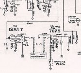
I'm trying to sort out why I'm not getting any reverb with a Fender Pro Reverb, circa 1971. The unit has been recapped (not by me), and the workmanship, component values, etc. look ok. Apparently, there was no reverb before the recap too. All of the tubes test ok, and the reverb transformer measures ok in terms of DC resistance: 800 ohms across the primaries, about 1 ohm across the secondaries. One thing that I'm suspicious of is the amplitude of a 1kHz signal before after the 500pF capacitor on the way to the reverb driver tube grid. My understanding was that combination of this cap and the 1 meg resistor will cut everything below 318Hz, and yet I'm seeing significant attenuation of a 1kHz as well as 2kHz signal. The resistor measures within 5 percent of spec, and I replaced the cap with no change.

The plate voltage of the 12AT7 driver is 434V, and cathode is 8.77V.

Schematic Snippet.jpg

Joining in Quest for Tiny Sub Power

Hey All,

Just starting out in my journey here. I am purchasing a couple Martin Audio Blackline XP15s and want to build my own subwoofer to compliment them for dance music events in the Boston area. I've been reading in here for a few days and I've decided to head towards building @chris661's Teeny Tiny PA 15". I need to learn how to use Hornresp and keep educating myself, but I intend to engage in more dialogue here soon. In the meantime, I have compared available 15" drivers in the USA and want to share that document with you as a peace offering. This is limited to Neodymiums with at least ~1000 watts AES Power Rating.

https://docs.google.com/spreadsheets/d/1nFezzD2rRuHEl3OoiFVE_G_wkyETeRWkpqqxkhpWy7Q/edit?usp=sharing
Screenshot 2024-08-21 at 3.06.42 PM.png


The teeny tiny PA 15" plans and information I found so far are here:

Oliver's 3-P Drawing With Hole-2.png


As_BR_Input_1.PNG


As_BR_Input_2.PNG


As_BR_SPL_1_and_2.PNG


I will probably build one first and assuming that goes okay just build one more for the time being. I will also be creating a spreadsheet of potential amps to use for powering these two next. It would be fun to have a little 4u rack containing a crossover, EQ, Subharmonic Generator, and an amp for running the subs.

Attachments

For Sale Dual Mono Waynes Preamp with built in Khadas DAC

I've been using a Dual Mono Waynes Preamp in my office but just recently finished my balanced Zen Mod Iron Preamp and need to move on from this one.

I built the unit into an Anthem Preamp Chassis but replaced the faceplate with a 10mm Modushop faceplate. The top cover has some scratches from age but hardly noticeable. The unit is almost exactly the same size as the Pesante 2u. Maybe a tad bit smaller.

Here are details on the preamp:

  • Dual mono - the PSU is the exact one used in the Whammy running at 17V per channel
  • 5 inputs AND a Khadas tone board Dac on selector switch position #1 (I ran my PC or a WIIM Pro directly into it)
  • Two outputs as well as a headphone output
  • A Fixed output
  • Mil Spec Silver wiring
  • Alps Blue RK27 50k Pot

Asking $550 for the unit and I will ship it for free.

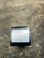
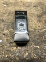
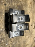
For Sale Pairs of Viborg Male Panel Mount Connectors (Gold Plated Copper)

Bought a ton of these from a member and kept the ones I needed for myself. I’ve used a couple on my builds and they work nice and look very high end vs the ones I was buying on Amazon.

Looking to sell them in pairs or could do a deal for the lot.
I’ve seen these listed between $18 and $30 each.

Asking $20 a pair and we can determine the cheapest shipping option available.

Attachments

  • IMG_1817.jpeg
    IMG_1817.jpeg
    267.4 KB · Views: 209
  • IMG_1815.jpeg
    IMG_1815.jpeg
    568.9 KB · Views: 209
  • IMG_1814.jpeg
    IMG_1814.jpeg
    405.4 KB · Views: 205

DIY Mic Preamp Circuit Noisy with Condenser Capsule

Hi Everyone

After my Project with the Phantom Powered Big Condenser Capsule and Balanced Output I started a new Project for a similar Microphone Preamp for a Large-Diaphragm Condenser Microphone.
But I got stuck with some noise in the Audiosignal after I connect the Condenser Capsule.
It's not the GND-Lift Noise, this I've already fixed.
My Problem is that, after I connect the Large-Diaphragm Condenser Capsule I have some Noise between about 160 to 2500 Hz.
If I disconnect the Capsule it is silent. I tried two different Condenser Capsules with the same Result.
I also replaced the LSK 489 B JFET with the one of my other Mic, where it worked silent, with the same Result.
I changed also the 1 Giga-Ohm Resistor with another an the other Components with the same Result.

There must be an fault in the circuit, but I don't have an Idea to fix that...

Grossmembran_mit_Polarisation_Schaltplan.jpg


The Q-Point and VGSOff I got from the Datasheet:

Mittelpunkt.jpg


VGSOff.jpg


The Equation for RD and RS:

RD: (V+ - (Volt Q-Point + (VGS(OFF)*-1))) / IDSS (A)
(48-(9+2.2)) / 0.0075 = 4906 Ohm
RS: (VGS(OFF)*-1) / IDSS (A)
2.2 / 0.0075 = 293 Ohm

I Uploaded on my Webserver an Example-Wav of the Noise: https://www.netcoast.ch/Noise.wav

I Produce the 48 Volts with a Boost-Converter (5 Volt to 48 Volt), but I also tested it with the Phantom Power from my sound mixer with the same result:

BoostKonverter5VDCzu48VDC.jpg


Thank you for your Help!

Best Regards
Lukas

Hello! Newbie here looking to learn

Hi, I've spent the last 2 months learning everything I could about speaker design. Went with a kit as most people recommended at first and hated the sound of it. So I've decided to design my own pair of bookshelf 3 ways. Looking to pick people's brains and get feedback on strengths and weaknesses of my designs. Also looking forward to providing my own perspective on things. Nice to meet everyone!

hello to all

my name is dor and im new mamber

I came here to learn from your extensive knowledge And maybe buy some speakers 🙂, i can contribute my knowledge abot room acoustics if anyone is interested.

Thinking of building the Satori Helios TeXtreme 9.5" 2-Way Speaker Kit

But still grappling with the question about how 10" can compere to 4.5" for mid freq and what I really lose compared to proper 3 way
thanks

hello!

Hi everyone. It seems to be common practice to make introductions, so here's a little about myself! I'm an electrical engineer that got out of the technical field pretty much right after college. Even though I don't do it professionally anymore, I'll always be an engineer at heart! I've always had a passion for tinkering, audio and for woodworking. I've been a longtime lurker on the site as it relates to speaker and crossover design and construction. This is a wonderful community of passionate individuals and is such a fanstastic resource.

Thanks,
Brandon

  • Locked
3e Audio TPA3251 TPA3255& PSU 200W 36V 6A Cheap

Hi Guys - I have a lot of 3e Audio stuff that I bought and have done nothing with. Just want to move it on to someone who will make the project and appreciate it.

Price drop

AMP Balanced/unbalanced TPA3251 & TPA3255 AUD45.00
PSU AUD45.00

First in best dress until sold.

Plus postage to where ever you are.

At this price PayPal family and friends.

Attachments

  • 3e-audio-amplifier-board-stereo-class-d-balanced-tpa3255-2x-225w-4-ohm.jpg
    3e-audio-amplifier-board-stereo-class-d-balanced-tpa3255-2x-225w-4-ohm.jpg
    106.7 KB · Views: 72
  • 200W 36V-6A Quasi-Resonant PSU For TPA3251-001.jpg
    200W 36V-6A Quasi-Resonant PSU For TPA3251-001.jpg
    231.4 KB · Views: 72

Mic Preamp with Differential Amplifier, which Zener Diode?

Hi Everyone

I've a little Mic Preamp Circuit for a large Diaphragm Capacitor Capsule.
Now I've seen in a Youtube-Video, that they use a differential amplifier.
I've added this also to my circuit, but they use a Zener-Diode from Ground to VCC (48 Volts).
But they didn't mention the specification for choose the right one.
It works without the Zener-Diode, so is my question do I need this or not? And why?
And how to choose the right one?

I need the 48 Volts also for the polarization of the Condenser Capsule.
I get the 48 Volts from Phantom-Power over the XLR (Pin 2 + 3 -> 6.8kOhm -> Capacitor).

I attached the simplyfied Schematic.

Thank you for your help.

Attachments

  • Circuit1.JPG
    Circuit1.JPG
    147.2 KB · Views: 199

Odd REW measurement of Dayton PS95-8?

Hi,

Playing with REW to measure different fullrangers, and probably made some configuration mistake or something, because on the last measurement getting +20dB on pretty neutral speaker such as Dayton PS95-8

Measurement setup:
0,8m measurement distance,
dbx measurement mic, only ~1month old
Presonus interface with 48V phantom power, as sound source also
Topping MX3 amp (I don' trust it!!!)
~10Liters MLTL with ~20cm wide baffle (Yes I know, that is an oversized box for this driver, but this was done for MLTL experiment - the question is about high frequencies anyway)

And the worst part... REW is not on pretty much default settings, it is a bit tuned according to https://kimmosaunisto.net/Software/VituixCAD/VituixCAD_Measurement_REW.pdf
Measurement levels are not matched, so there is no 120dB levels, everything was done on around ~95dB I think. I made no level matching this time - it is my fault.

There is a ~20 and even ~30dB rising response, from 2.5kHz to 15kHz at 0 angle, 15 and 30deg angles, which seems odd. When compensating it with EQ down this response to similar levels - 10-15dB on 4-15kHz - it sounds off. If I EQ it a little less, from 5-10dB - everything sounds more or less correct...

Measurements on 1/6 oct smoothing, as picture below, also as attachment.
ps95.png

When looking at various PS95-8 tests, benchmarks and so on - it is pretty much neutral speaker, there are no measurements like mine.

The problem is that I have pretty good ears, not fully "golden" but pretty close to it. I can hear up to 14-15kHz, and definitely from 5-10kHz, done many hearing tests online with pretty good results.
So I somehow started to doubt my setup. Tomorrow will measure all the available speakers and other amps at hand, now it is too late. Have TC9 at hand, and measured it before - there were no such rising response as I remember.
The question is:

My ears assumed, that this massive 10-20dB rising response is "nothing extraordinary", and I should trust measurements?
Setup is wrong? REW?
Sound level is too high and amp adds some kind of protection?
Mic is bad?
Level matching is ok, and that little speaker generated those 120+ dB sound levels????

What are your ideas?

Attachments

Which affordable class D amplifier to pick for playing metal LOUD?
My journey with amplifiers began when I really got into music—specifically metal, where low distortion and high clarity at high power are non-negotiable for quality listening and peak enjoyment. I built several decent passive speakers, mostly using parts from Samsung, Sony, and LG media centers. I experimented with some Russian gear like the S30. But what does a passive speaker need to run? Obviously, an amp. My first amp was a Bluetooth-integrated TPA3116 50w*2-based ZZ-Hifi board. It performed well for three years, but then the Bluetooth module started acting up. No big deal—I used a separate module. A few months later, the audio quality went to hell. Upon investigation, I found that the chip itself had burned out, lack of cooling? doubt it. whichever it is, the amp was robbed from caps and inductors by me, the rest is history.

Next, I tried two TPA3118 60w mono boards in stereo configuration. They sounded better than the TPA3116 but died after just a week. The reason? Simply unplugging the aux cable caused them to burst into flames. I bought two more of the same boards, and once again, unplugging the aux resulted in flames. Apparently, these boards have a serious design flaw. Frustrated by this, I decided to buy an amp that seemed like a god amongst these Chinese PCBs—the TDA7498E. I added Bluetooth, and it worked great for a few weeks. But then it started shutting down at any moderate volume, while still managing to play at low levels. The amp was utterly gutless, lacking any real bass.

If I were to rank these amps by sound quality, it would look like this:

1. TPA3118: Clear, dynamic, and actually sounded powerful. (5 bucks each)
2. TPA3116: Clear, powerful, and had some weight to it. (25 bucks)
3. TDA7498E: Mediocre clarity, didn’t sound heavy, and failed miserably to sound powerful because of its poor clarity. (50 bucks)

In the end, the recurring issue was always the chip itself. After further investigation, I realized these problems are a hallmark of cheap integrated Class-D amps. fixing them requires a full chip replacement, which, while I can do, isn’t worth it.

So now, I’m left with two options: a discrete Class-D amp or an AB class amp. I’m really liking the Wolverine amp and Project65 from BuildAudioAmps.com. Any help? all advices will be greatly appreciated!

Tubelab SE / Simple45 build: Why 5842/417A? Why not 6J5?

Note: I recently started a thread with the same name on Audiokarma.org.

I'm preparing for a Tubelab SE (or SE II) build with 45 tubes. I have a pair of NOS Tamura F-475 OPTs and couple of hunkin' PAECO PT's, though one of those should be plenty. I was getting ready to pull the trigger on a tube order from Brent Jessee, but his stock of 5842/417A tubes seems to have evaporated. I said to myself, "Well, self, we might as well get into some calculations loadlines while we ponder where to get some sweet driver tubes!" I annotated the SE II schematic and plotted up a few loadlines for the 45 tubes. Of course, the loadline for the 5842 is dead simple because the design uses a constant current source (CCS) on the plate, so the loadline is just a horizontal line. I found that the CCS is spec'ed for 12 mA, and the quiescent plate voltage is typically 175 V. Wait, what? Sure, the 5842 can take a max plate voltage of 200 V, but none of the characteristic graphs include lines for anything over 150 V. Moreover, the spec plate current is 26 mA at 150 V. That's an operating point that appears to give the tube some room to breathe, whereas 12 mA at 175 V is crammed down into the lower-right part of the plate characteristics.

Then, I look into necessary signal swings for the 45: 36 Vrms on the plate with mu=3.45 means 10.4 Vrms on the grid, or a swing of +/- 14.8 V. Even with the operating point of the 5842 crammed into the lower right, that should be fine and would require, wait for it, 0.243 Vrms on the grid of the 5842. Quarter-volt sensitivity? Jeez, seems kind of ridiculous, but OK.

Still, might another, more readily available tube do the trick? The Powerdrive stage in the design (i.e., MOSFET source follower between driver and output stages) seems to open up a lot of options. I look into the 6J5, which is the single-triode equivalent of the 6SN7. It has less than half the gain (mu=20 vs. the 5842's mu=43), but all that gain of the 5842 seems a bit over the top. Plus, there seem to be issues with the 5842: It's microphonic, and according to one post, it threatens to oscillate while sitting in the cardboard box.

So why fuss with the 5842? Why not the 6J5? It has low distortion, and mainly 2nd harmonic. With less current and substantially higher, but still reasonable, plate voltage, the operating point can be smack in the middle of the plate characteristics graph. Thoughts?

A summary of some replies to this post on Audiokarma.org:
  • Some recommend ditching the Tubelab design or aspects thereof.
  • I could probably use 6J5's, and it might be fine.
    • The 6J5 is pretty awesome.
    • But the lower gain of the 6J5 would make the amp less dynamic-sounding.
  • Turns out the 5842 works really well with the Tubelab design.
    • Yeah, the operating point is a bit weird, but don't worry about it.
    • If you find you don't like the original operating point, the design has a lot of adjustability built in, and you can change the operating point in conjunction with testing.
    • 5842 tubes are available at reasonable prices. (Subtext: You don't have to go with the WE's or Amperex gold pins.)
  • The PCB schematic is annoying to some curmudgeons, but I'll have to live with it. Or make my own. Whatever. And get off my lawn!
  • I should probably put my question to a couple of other forums, including DIY-audio, where I'd likely get a response from the designer, George.
Per the last point, that's what I'm doing! Thanks in advance!

Paradigm Phantom V4 Crossover Upgrade

Hi Everyone,

I am new to the forum and not sure if this is the good topic for the group or not, if not just let me know. I have been reading a lot about how upgrading crossover components can improve speaker sound. I have a collection of old to newer speakers that I would be interested in doing this to. So to start I'd like to get my feet wet with a old set of Paradigm Phantom V4 speakers as an experiment. They are in great shape and I use them in my basement workshop. Better sound is always good, learning about crossovers and how to do it would be even better at this point.

Here are the specs I could pull together
3-driver, 2-way bass reflex, quasi-3rd-order resistive port
High-Frequency Driver : 25mm (1in) CMC™ ceramic/metal composite dome
Two 165mm (6-1/2in) MPC™ metallescent cones, GRIP™ chasis
Frequency Response : 49Hz - 20kHz, +/- 2dB (on-axis) 49Hz - 18kHz, +/- 2dB (off-axis)
91dB / 88dB
15 - 160 watts
8 ohms

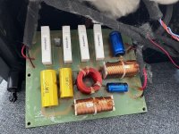
The crossover is pretty basic. One electrolytic cap (4uF 100 V), 1 resistor (10 W 2.2 Ohms - I think) and two induction coils (no information). For experience I'd like to replace all the parts. I have two questions. 1) can I use a 4.7 uF 100V cap instead of 4 uF (could not find a 4uF film cap) and 2) what do I get for induction coils? There are no identification markings. Crossover pics attached.

Thanks in advance and if not appropriate just let me know. Best,

Attachments

  • Phantom 1.jpeg
    Phantom 1.jpeg
    59.1 KB · Views: 76
  • Phantom 2.jpeg
    Phantom 2.jpeg
    52.9 KB · Views: 75
  • Phantom 3.jpeg
    Phantom 3.jpeg
    54.2 KB · Views: 66

Hello from Montenegro

I have the same problem with Canton Ergo As 2 subwoofer as friend of @e_fortier from this tread https://www.diyaudio.com/community/threads/canton-ergo-sub-seeking-schematic.413258/. Andre from Canton after-sale service said that i need pay 200 euro for new amplifier, in my letter from 13 august, i try to explain Andre my financial situation, that i can't by new audiodevices, thats why i buy Canton 122DC from 90's and need to repair sub from 00's. Now after a week of waiting I'm confident that Canton do not provide me this information. I hope @e_fortier can help me with this.

Attachments

  • b9f23c4d-7091-4bd0-a495-b1f3c11c2f6f (1).jpg
    b9f23c4d-7091-4bd0-a495-b1f3c11c2f6f (1).jpg
    117.5 KB · Views: 47

Modified CBT24

I have long been looking at the Don Keeles CBT36 line arrays, but was intimidated by the insane amount of tweeters. Recently I happened to search for his work again when discussing speakers with a friend and noticed that now an other version exist, CBT24, that looks to be a somewhat easier build.

The kit has been discontinued by parts-express: Epique CBT24K Line Array Speaker Kit Pair

But inspired by Jim Griffin here I have started building my own (duplicating his build).

I have started cutting out parts for the enclosure (going to build the enclosures before blowing $1k on drivers 😛 ).

Image of the routing.

More images as the build progresses 🙂

I am a bit new to the world off full-ish range speakers that benefit from a subwoofer. If someone has any tips for a matching subwoofer build I would be happy for advices 🙂 I will probably order parts from here: Audio Components

I have looked at these subwoofers: Seas E0026-08S W26FX001 and Dayton Audio RSS315HFA-8 12", should I have one or two subwoofer boxes?

Help with biasing Rockford Fosgate mosFET amplifier
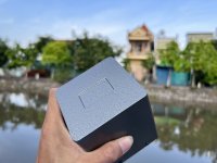
I just finished rebuilding this Rockford Fosgate amplifier and I have a thread going where I asked about proper bias current. I didn’t get much as far as hits on that thread, Nelson said 30 mA per device is “a healthy start”, so I am going to just set it there. There are 16 MOSFETs per channel so that would be .24 amps per rail, but sadly I can’t measure the rails unless I remove the large blue buss bar which I guess is and option.
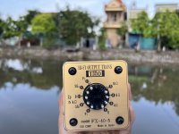
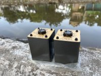
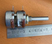
IMG_2372.jpeg


So what I did is, I measured across one of the one ohm source resistors and adjusted bias until I saw 30 mV across that resistor which would equal 30 mA. Both channels perfectly even. Well one channel got quite a bit warmer. I checked all of the other source resistors and found that the voltages were all over the place, that’s when I found that these are not like emitter resistors on BJTs. On the cooler channel, the resistor I was measuring on was about the average most of them being in the 30 to 40 mil range while a couple were as high as 50 and some as low as 20 mV. While on the channel that ran warmer, the resistor that measured 30 was actually on of the lowest measuring, most of the resistors on that side were in the 50 to 60 mV range with a few at about 80 mV.

I’ve been doing some reading and I found others. They have had this situation and this shows the importance of matching your MOSFETs. So these people went back to their PB to get better matched sets. Well this is from the factory this way and I’m not gonna be able to better match 32 MOSFETs. I currently don’t have any spares of these models so I would have to buy a whole bunch.

So how would you recommend to best set bias on this? Should I just remove the buss bar from one rail? I could just make sure that the current draw on the positive rail is the same for both channels? I’ve read that the source resistor is generally the way it is done, but how exactly when the measurements are so different from each other. Do I just go for an average? Write down all the measurements I get for each 16 for each channel and average them out?

I really appreciate any help I can get with this. I don’t mess with mosfet too often, be a good learning experience.

Thanks,
Dan
  • Like
Reactions: SirPaulGerman
Projects by fanatics, for fanatics
Get answers and advice for everyone wanting to learn the art of audio.
Join the Community
508,467
Members
7,920,903
Messages

Filter

Forum Statistics

Threads
407,832
Messages
7,920,903
Members
508,467
Latest member
AmcAmx