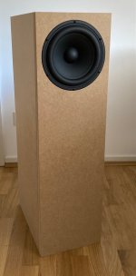
Need some help with my woofer and its port. Getting huge rise in deep bass out of this Peerless 8"

What I did:
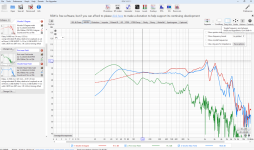
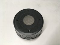
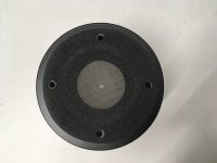
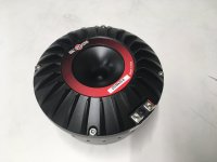
Took full measurements of my 3 including this Peerless 8" woofer here.
Took near field of woofer
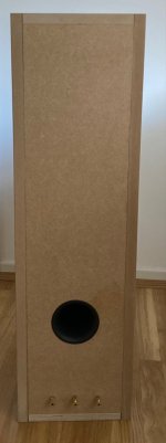
Took near filed of port
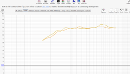
Took far field of woofer
Aligned near field measurments SPL to the near field SPL so that I can use the far field measurement for my crossover design (mic never moved between measurement of the other 2 drivers so this should keep the SPL and phase aligned for crossing over purposes)

What I don't get:
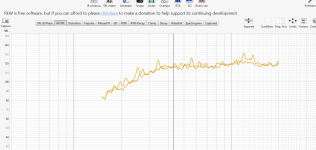
1. I kind of understand the giant rise from the port as expected something like that but this seems excessive
2. Why the woofer near field starts to rise up dramatically as well around 100 hz

Is is possible that the port output leaked into the woofer near field measurement? Is is literally about 5 inches below the woofer and this would explain a lot

It is also VERY possible I do not know what I am doing with REW. If so, please let me know. I am very good at following directions and I tried very hard to follow the REW directions to the letter.

One last question..... Do I need to combine both the nearfield woofer and port measurements to accurately crossover the woofer with the mid? I would think the port acts almost as its own driver so its response would need to be added to that of the woofer, yes?

Attachments

Measurements and VituixCad Model Correlation

Sorry a bit of a long post but need to get some knowledge from the group before I spend too much more time on this.

I have taken a set of baseline measurements of my 3 my speaker in an anechoic chamber (chamber has a null at 60hz but above 200hz there is no need for gating, very clean data). The measurements taken were -
  • Microphone at the same position for all, 1m from centre of baffle at tweeter height.
  • I had the acoustic timing bleep turned on but this was played through the driver being measured (now I know that you need a second speaker for this to work properly, doh !) therefore all measurements start at 20ms which seems to suggest the data has no acoustic offset built in, is this correct?
  • I measured the Woofer (WO24P-4, 40L sealed stand mount monkey box), Mid (EM1308, includes a 39uF protection Cap) and Tweeter (ET448, Includes a 12uF protection Cap) at +/-90,75,60,45,30,20,10,0 degs on the horizontal axis. I did meaure the Mid and Tweeter withouth the protection Caps as well but will be running an active system with them included.
  • I also measured the individual drivers and also driver pairs (woofer/mid, mid/tweeter).
  • Finally, I did some nearfield measurments for the woofer both on tweeter axis and the woofer axis at 1cm, 30cm, 60cm and 1m.
Now the conundrum:

Using the pairs technique by loading the individual driver measurements and the paired data into VituixCad I can adjust the delays to make the summed individual match the pair data. This results in -

Woofer/Mid - Mid is -270uS which equates to 93mm this is not far from a geometric calculation using Pythagoras (88mm).
Mid/Tweeter - Tweeter is +20uS which equates to 6.9mm which again sounds about right for a dome mid and dome tweeter.

That said, I modeled up a crossover in VituixCad without adding the offset above, measured the combined speaker response (also with inverted mid to get nulls) and individual driver. The whole speaker model vs measured response matched very well and the step/impulse response also was pretty comparable. Which seems to suggest the data has the acoustic offset embedded in it and my method seems to be correct but something doesn't quite add up with respect to the acoustic offset.

So, the questions is what do I do with the offset data calculated with the pairs approach or have I measured the speaker incorrectly or have I lucked out on my measurements/modelling approach ? Any help will be very welcome and gratefully received, thanks in advance.

For info - if I add in the offsets as delays into VituixCad it is almost impossible to get the phases to line up between the Woofer and Mid.
As an aside after I did this comparison I slightly altered the VituixCad Model2a (2a1) by upping the Tweeter delay to 30uS and slightly changing to the High/Low pass which brought the phases into alignment right up to 15kHz, maintained the flat on axis response and maintained the deep nulls.

I can post the REW mdat files for the three drivers if anyone want to have a play.

Attached is a number of plots showing:
  • Woofer/Mid Offset at Mid= -270uS
  • Mid/Tweeter Offset at Tweeter = +20uS
  • VituixCad Model2a (my model designation)
  • VituixCad Model2a vs Measured full speaker and individual driver responses (note the null at 60hz if from the chamber)
  • Step Model2a vs Measured
  • Impulse Model2a vs Measured
Mid Tweeter Delay +20ms 6.88mm.jpg Woofer Mid Delay -270ms 92.9mm.jpg
Model 2a Vituixcad.JPG Model 2a comparison.JPG
Step Model2a vs measured.jpg Impulse Model2a vs measured.jpg

For Sale B&C Speakers DCM420 Ring Radiator Midrange Compression Drivers

Attachments

  • IMG_0808.JPG
    IMG_0808.JPG
    284.4 KB · Views: 113
  • IMG_0809.JPG
    IMG_0809.JPG
    392.2 KB · Views: 120
  • IMG_0810.JPG
    IMG_0810.JPG
    228.5 KB · Views: 130
  • IMG_0811.JPG
    IMG_0811.JPG
    204 KB · Views: 130
  • IMG_0812.JPG
    IMG_0812.JPG
    218.4 KB · Views: 124
  • IMG_0813.JPG
    IMG_0813.JPG
    212.7 KB · Views: 120
  • IMG_0814.JPG
    IMG_0814.JPG
    213.7 KB · Views: 118
  • IMG_0815.JPG
    IMG_0815.JPG
    395.7 KB · Views: 128
  • Like
Reactions: D&C_Audio

Anyone know what's going on with Elektrotanya website?

Hi:

I'm trying to respond to a post on Elektrotanya. Their website seems rather messed up.

A few days ago, it threw an error that I couldn't log on because I was using the wrong usernmame/email or password. I keep all my login credentials in a password program, so I know they were correct. So I reset my password. I logged on, and made my very first post.

Today, Elektrotanya is once again complaining that my user/pwd combination is incorrect. I'm using what I had saved in my password program from just a few days ago. So I go to reset my password AGAIN. This time, it doesn't send me the email to reset my password. I tried 3 times.

I looked for 15 mins. on the site to find a contact us page, but couldn't find one. I finally wound up having to use Google search to find the Contact page.

Once at the Contact page, I tried to send a message, but I kept getting the error: "The answer you entered for the Captcha was not correct". I clearly screwed up the first attempt, but my next attempts kept throwing that error, even though there were no pictures to click on. Nothing!

This of course eventually led to the error:
"CAPTCHA session reuse attack detected."

even though I wasn't attacking anything.

Does anyone have any way of contacting the site owner so maybe this could be fixed, or at least he could be informed of it? Logon seems to be quite a hot mess over there.

Restoring ReVox G36 MKIII - Expert Opinions Solicited

I resurrected an old thread on the revox, so far the only responses have been to the original post from over 3yrs ago so I will not make that mistake again. :whazzat:

Anyway this fairly nice ReVox G36 MKIII 117V North American edition half track recorder fell into my lap recently and although I have worked on many of these decks and am relatively comfortable working on it, it has been a long time since the last one.

Long enough that although the selenium rectifiers and electrolytics all test good I seriously think I should without question replace them. Seems logical except that the design is so efficient that I will have to make significant changes to get voltages right. The only source of drop in replacement caps (vibroworld) seems to be gone, and no one seems to be able to tell me whether most decks still running are still using the stock supply components. Realistically at 42yrs out I would assume this is skirting disaster.. It's just that this deck is virgin and I want to do the updates with comparable parts that don't leave it looking like a hack worked on it.

This machine seems to be a low hours unit and hence should have a long remaining service life with care.

I'm also planning on some mods. Charlie King recommends removing the 5W PP amplifier which makes sense as this generates most of the heat in the electronics section due to its dissipation.

In addition the current input amplifier provides far too much gain with modern sources and basically I don't need it at all. I plan to just go right in at the recording level control. I could eliminate a further two tubes doing this if I so choose, but this would require modifying the dc filament supply. (Probably a performance enhancement actually)

I've replaced a couple of electrolytics in the replay electronics.

I have not yet run the deck, but I am told this is a high speed version. (7.5ips/15ips) I have not been able to prove or disprove this.. I have 15ips recorded tapes so that will be the acid test once I get it powered up.

Anyone have a guess as to what type of caps the motor phase shift caps are, and whether I should replace/rebuild (new caps in old cans?) On older versions these actually can present an electrical hazard due to leakage into the chassis. The 117V version runs the motors off of a dedicated winding on the power transformer and the motor circuitry is fully isolated from the mains.

I've provided a schematic of my version for the curious or helpful.

I'm really looking for insights, comments, advice and encouragement from people who are still working on these decks.

Attachments

  • schematic_bw.gif
    schematic_bw.gif
    45 KB · Views: 2,148

4x stereo output via S/PDIF?

For one application (Linkwitz LX521) I need to at least temporarily use a MiniDSP NanoDigi. Are there any concerns about the DIR in the four stereo DACs used drifting apart?
I already have 2x SMSL 10th MkII (AK4493). I was thinking about getting either two more SMSL SU-1 (AK4493S) or SMSL PS200 (same stripped down case and display as SU-1, but ES9039Q2M). I was not too thrilled listening to earlier incarnations of ESS DACs (Motu M4 and Ultralite Mk5, Topping DM7), but the ES9039Q2M seems to be a different animal based e.g. on archimago's measurements. I also noted the manufacturer distortion measurements of the PS200 show no hint of an ESS hump but rather a slight increase from about - 5 dB FS, which is very similar to how AK4493 behaves.

If there are concerns, is there a way to use one DIR/DAC as the master and slave the others to it? I remember this was possible with some DIRs but I have no idea whether even a separate DIR chip is used in these.


The alternative would be building an 8 channel I2S in DAC as there are currently no attractive options on the market, but that is something for another thread.

PS: just realized the 10th mkii is one of the few modern DACs that still have a jitter issue with S/PDIF or optical in 🙁

https://www.audiosciencereview.com/...ds/smsl-sanskrit-10th-mk-ii-dac-review.12148/

The SU-1 seems to be a lot better in this regard (even if Amir only tested optical in):
https://www.audiosciencereview.com/forum/index.php?threads/smsl-su-1-stereo-dac-review.44029/

Stated power consumption of a component

G'day Guys,

Commericially built equipment will normally have a stated power consumption.
For example:
HK.png


If I was to do the same on a DIY power amp I am building.
Do I:
A) state the maximum possible power output of the power transformer, in my case 300w or 420VA (according to the pioneer service manual it was salvaged from)
B) the maximum power that is likely to be drawn from the power transformer. Eg: 100w into 4ohm
C) B + a derating factor for power loss in the transformer say 0.6. Eg: 100w/ 0.6 = 166W

positive (sound) vibrations

Hi everyone,
after reading for some time i signed up to join the conversation.

i am an artist from cologne, germany, and have been working with sound literally since i was a kid.

my main interested currently is to build sound system of different kinds, organizing free events with friends and such.
started building speakers again recently, fun things like the solar powered sound system bike in my avatar picture.

looking forward to exchange ideas and knowledge!

best, Julius

Martin Logan Sequell II repair

I joined in 2007 and this is now my first post, my unfortune one 🤐
In the early 90s in younger years I bought me a pair of Martin Logan Sequell II which after these years I still have. I replaced the foiles at about 2012 at the local Martin Logan representant, cause one of the speakers stood near to a window, which was often opened. Never do this again.
In the last years the panels moved downwards and I had to align them again. This was no problem until one of the speakers had a losen transducer connection. I could solder this without problems, it worked now for a few years.
But now I tried to fix it again, casue the panels went down again. And my soldering was not succesful for what ever reason. I cleaned the solder point and used a high quality solder.
The soldering point looses immediately, no way to get it soldered at that original point again.
Does anybody have an idea how to fix this, I now ordered a special glue with electrical conductivity, but that's not proven to work.
Appreciate every possible solution.

Attachments

  • 20240720_164242.jpg
    20240720_164242.jpg
    857.1 KB · Views: 64

The Mystery and The Magic of Mr. Pass’s Signature Amplifier

Though as it turns out I know some of you I am the knew guy so I apologize in advance if this has been covered before. I have searched and searched, turning over every rock and Googling every combination of words I can think of and can find nothing, no answers to what I thought to be noteworthy and reasonable questions.
It is my claim though I expect his as well that the Stasis 1 amplifier is in fact Mr. Pass’s signature piece. I would go even farther and say it is the most important amplifier of its era.
When I was still a teenager I was fortunate to have had an opportunity to hear the Stasis 1 amps feeding a pr. Of Magnaplanar MG III’s at the 1980 CES show in Vegas. I was quite familiar with the MAGGY’s already, at least I thought I was. I knew them powered by BRYSTON 4b’s and even stacked Naim 250’s but this was something else. I remember the new hit Money For Nothing just starting and immediately was mesmerized. I had no idea those speakers could sound like that, I already thought they were amazing but was about to learn what they could sound like. If ever there was a speaker to demonstrate what big class A power could do this was it. They revealed in the most obvious way a whole new dimension , an unveiling of there potential that came almost like a shock. It was as if they were thanking you for giving them what they needed. Pure class A at 200 watts, un compromised by the demands of sub 2ohm impedance with a truckload of current the amplifiers were just as happy as the speakers were. Not even the bigger Audio Research amps could pull that off. It was and is still my most memorable listening experience that I have carried to this day.
My point here is having brought to the market pure class A with enough power to wake up any speaker just had not been done! 200 watt class A, impossible, you will burn the house down as your listening room turns into a sauna! Nope. Cool and confident. Mr. Pass built what I believe to be possibly the most iconic amplifier of our generation. Gordon Holt still today runs them in his personal system along with his big Infinity’s. 44 years later they are still ready for a showdown with anything new. Built by hand with nothing short of military grade spec they have aged very well.

What the mystery is, to me at least is carved into the faceplate it says “LIMITED PRODUCTION”. Something decided in advance. I know of no other maker to limit the numbers except by how many they can sell. True to those words production stopped after a very successful 3 years of strong sales. It’s not like the SA1 was waiting in the wings as it would be another 3 years before it was introduced. Mr. Pass had made his mark and during those three dry years I think the Stasis 1 was talked about more than when you could go buy one! Of course given they shared the same topology the 800a and the 400a enjoyed great success. My theory is that Mr. Pass showed some brilliance outside of his engineering skills with a masterfully conducted marketing campaign. The three year drought left a thirsty public anxious and wondering about the rumours about a new version coming out, which it did and the SA1 was welcomed by thankful audiophiles everywhere and remained in production for as long as Mr. Pass was there to make them. Now the SA1 is not the same as the Stasis 1 at least in so far as it is 160 watts and not 200 but it is the other differences between them of which I can find no information. My theory being is the Stasis 1 was made no holds barred and Mr. Pass was all in on shining a light on the new technology but was aware he wasn’t making any money on them so understood limiting them made sense and would create an aura about them generating interest. Now the SA1 came out three years later and at a higher price becoming an instant sales hit. Threshold declined at the time to comment on any difference between them making sure the Stasis 1 version stopped getting attention. I can find nothing that compares the two anywhere, if you Google the Stasis 1 it thinks you mean SA1 and makes no difference between them.
I don’t think it has happened before so I think it’s time for Mr. Pass to come clean and give us what he knows in describing the engineering / design and sonic variables between them.
I believe he will agree with me that the Stasis 1 is his signature piece and the time has come to correct my theory or agree.
After not hearing them again since, I did after 44 years finally get a pair of Stasis 1’s, as a matter of fact two pr. From an aging Cowboy in Colorado who bought six in 1980 serial #’s 79-80-81-82
I have become obsessed with finding any competent commentary discussing the differences and look forward to your or any response sir with the faith of a child on Christmas morning.
Peter Smith

Passive subwoofer crossover

Hi !

I'm building a passive subwoofer for my home theatre and also for listening music (I don't know if it's the right place to post).

My amp will never be above 120 W (i think). Just in case I push the value for 150W.

My constraint are :

1 - High quality sound (highest i can)

2 - 20 - 250 Hz (closest i can)

3 - Around 100€ for the driver (max 150€)

4 - Box max dimensions (inside) : 550 x 500 x 2000 mm

(I have dayton audio speaker that Kirby Meets Audio designed on youtube, those are quite great but it lacks of bass)

----------------------

I found (soundimorts.eu) :
73€ - Dayton Audio SD270A-88 10" (Green)
149€ - Dayton Audio DCS305-4 12" (Blue)
109€ - Dayton Audio SD315A-88 12" (Red)

On winIsd, for a ported enclosure :

2022-04-14_11h51_17.png


Budgetwise : SD270A-88 but too high above Xmax (at 120W)

So, Budgetwise 2 : SD315A-88 but too higher than Xmax (at 120W)

Last choice : DCS305-4 almost down to where I want, spl, group delay, cone excursion, rear port air velocity OK !
--> 120L box, tuned at 23Hz
--> 500x40 mm port (lenght 825.8 mm) BUT the 1st port resonance : 208Hz ; is not an octave above my desired LP filter.

And then, I'm completely lost on the crossover design, I made a 4th order, but it seems that it will cost so much...

2022-04-14_12h12_46.png


So here are my questions :

- Any Ideas of other greater drivers ?

- Does a subwoofer need to go as high as 250Hz ?

  • How to define the 1st port resonance ? (I read that this should be 1 ocatve higher than the LP filter)
  • How to design better to meet all the requirements ? (1st port resonance, cone excursion, group delay, ...)

- Could you help me design a low budget crossover ? (I don't have much experience, I'm learning everything to achieve it)

My WinIsd files are also attached.

It might be too difficult to meet all these goals but I'm willing to get as close as I can !

Thank you very much for any answer !

Olamm

60 WPC Amplifier for DIY Turntable Motor Drive

I've identified a great little stereo amp that works well with the SG4 sinewave generator for use as the output stage and motor drive for AC synchronous or AC induction turntable motors. It is based on a pair of the venerable LM3886 chip amps and contains everything needed to boost the SG4 signal up to a level needed to drive a 6V to 115V (or 230V) transformer. The only additional items needed to make a complete motor drive system is the AC input power transformer, the output transformer, the SG4, a heat sink and a slight modification to the amplifier. A complete motor drive can be constructed for ~$100 plus case.

The amp is available on e-Bay for $15.17 including shipping:

60W LM3886TF Sound Audio Amplifier 2-Channel Digital Power AMP | eBay

The amp will need to be modified to reduce the gain for two reasons:

1. The SG4 output is 5VPP and the amp will go into clipping at ~0.75VPP input.
2. With the standard gain, the output waveform becomes quite distorted when connected to the output transformer. With reduced gain, distortion remains very low, even when driving heavy loads and even at 50Hz. If you do not modify the MK-154 gain, the output waveform will look terrible, especially at 50 or 60Hz.

Replace or parallel the two 22K resistors with 2.2K resistors as shown in the attached jpeg (MK-154 Modified.jpeg). With this gain setting, the 5VPP output of the SG4 will drive the output of the transformer to ~125VRMS with very little distortion.

The amp PCB has screw terminals for the AC input, removable connectors for the outputs and both a 3.5mm stereo jack and 3 pin header for the audio inputs.

I've created wiring diagrams for 3 different scenarios:

1. 115VAC input and output single phase.
2. 230VAC input and output single phase.
3. 115VAC input and output dual phase.

The design uses two low cost split bobbin transformers with dual primaries and dual secondaries. The AC input transformer is a Signal LP24-2000 (48W) and the output transformer is a Signal LP12-1900 (24W). Both are available from Mouser ($24 and $19 respectively).

For 115VAC input or output, the high voltage primary windings are connected in parallel. For 230VAC input or output, the high voltage primary windings are connected in series.

Warning: Working with high voltage can be dangerous. Do not attempt to wire these circuits unless you are comfortable and competent to work with high power and high voltage electronics. If wired incorrectly, damage to property and great bodily harm may result.

The wiring diagrams are labeled with the pin numbers on the transformers and are unique to these two parts. If you substitute different transformers you must be aware of the winding polarities of the coils, which are usually indicated with a "DOT". When connecting windings in parallel, the "dots" must be connected together on one side and the non-dot ends must be connected on the other. When connecting windings in series (for 230VAC input or output), the dot on the lower winding must connect to the non-dot end of the upper winding.

When working with AC line voltages, ALWAYS use fuses on both the input and output. The AC input transformer in the attached jpegs has an IEC socket with built in fuse holder for connection to the mains voltage; the fuse should be rated for 1A Slo-Blo type. The AC output should also have a 0.5A Slo-Blo fuse in line with the hot lead. Connect the earth safety ground (third/green wire) from the input connector to all chassis components (and the 3rd terminal on the AC output) to properly ground them.

The MK-154 PCB has detachable connectors on both the L & R outputs. Remove these for easier connection to the output transformer low voltage secondary windings and the transformer will then just plug in for assembly.

For single phase applications, both L & R audio inputs to the MK-154 are connected together and are driven by the 0° output of the SG4. The L & R outputs of the MK-154 are used to drive each winding of the dual low voltage secondary on the output transformer. When wired in phase, they will combine both channels into one output, doubling the current capability.

For dual phase applications, the 0° and 90° outputs of the SG4 drive the L & R audio inputs of the MK-154. Each MK-154 output (L & R) drives its own output transformer with the low voltage secondary windings on each transformer, connected in parallel.

Note that the output connectors on the PCB are mirror images of each other, so the + & - connections are not on the same side of the PCB for each connector. They will be on the same side of each connector that plugs into the PCB.

The MK-154 MUST have an adequate heat sink attached to the two LM-3886 output amps for proper operation. Failure to use a heat sink will result in almost immediate destruction of the amplifier. Use a heat sink with at least 40 square inches (250 cm²) of surface area and at least 2-3 inches deep. The LM3886 chips are in an isolated package so they do not require mica insulators between the chips and the heat sink, however, you will need to use silicone heat sink grease.

If you use the 3.5mm audio input jack to the MK-154, the tip is Right In, Ring is Left In and Sleeve is ground.

Attachments

  • MK154 Modifed.jpg
    MK154 Modifed.jpg
    388.1 KB · Views: 6,049
  • Input Cabling.jpg
    Input Cabling.jpg
    216.2 KB · Views: 6,034
  • Output Cabling.jpg
    Output Cabling.jpg
    205 KB · Views: 5,829
  • SG4 Cabling.jpg
    SG4 Cabling.jpg
    258.7 KB · Views: 5,772
  • System Interconnect.jpg
    System Interconnect.jpg
    221.3 KB · Views: 5,913
  • Single Phase 115V In-Out.jpg
    Single Phase 115V In-Out.jpg
    513.4 KB · Views: 2,537
  • Single Phase 230V In-Out.jpg
    Single Phase 230V In-Out.jpg
    524.9 KB · Views: 2,371
  • Dual Phase 115V In-Out.jpg
    Dual Phase 115V In-Out.jpg
    646.3 KB · Views: 2,314

Lower than low: Qtc

Here is the list of Qtc and their characteristics from the textbook.

Qtc = 1 is Chevbychev
Qtc = 0.707 is Butterworth
Qtc = 0.58 is Bessel
Qtc = 0.5 is Linkwitz-Riley

Most of the textbooks explain all of above alignments clearly including the case that Qtc is greater than 1. Unfortunately, I couldn’t find the explanation of Qtc of lower than 0.5.

I’m curious what will happen if I design the passive crossover with extremely low Q—lower than 0.5. For example, Q = 0.25.

In fact, I have tried experimenting already; with the traditional second-order crossover. But, I couldn’t hear anything abnormally. So, I’d like to ask for clearer explanation of the results/effects when utilizing the extremely low Q crossovers (lower than that of L-R alignment).

ICEpower 80AM2

Hi,

I have a bunch of ICEpower 80AM2 amplifiers. These are 2x80W or 1x160W BTL.

They don't have an integrated PSU as they work with the ICEpower 400SM power supply, that can power 8x 80AM2 amplifiers.

The 400SM power supply is expensive around USD$180 so I am looking for cheaper alternatives. AFAIK these amplifiers run on a dual +/-36volts power supply.

Do you think it might work? Do you have any recommendations on power supplies? What about some Hifime SMPS300RE?? (IDK if its better price wise). Maybe some Meanwell?

Looking forward to your suggestions!

Cheers.

Sound is just push and not pull?

Hi ! in a very interesting article by Mr Pass describing is project called the Zen amplifier
https://www.passdiy.com/project/amplifiers/the-zen-amplifier
i was struck by this passage
Simplicity is not the only reason for the use of the single-ended topology. The characteristic of a single-ended gain stage is the most musically natural. Its asymmetry is similar to the compression / rarefaction characteristic of air, where for a given displacement slightly higher pressure is observed on a positive (compression) than on a negative (rarefaction). Air itself is observed to be a single-ended medium, where the pressure can become very high, but never go below 0. The harmonic distortion of such a medium is second harmonic, the least offensive variety.
It is occasionally misunderstood that single-ended amplifiers intentionally distort the signal with second harmonic in order to achieve a falsely euphonious character. This is not true. Low distortion is still an important goal, and it is my observation that deliberate injection of second harmonic into a musical signal does not improve the quality of sound.
it seems to me that this position has solid bases. For instance a good compromise could a single ended front end followed by a push pull amp for convenience
I have also read that output pairs made of two same npns given their nature could sound more push than pull and in this way behave more like a single ended amp ?
I would try the single ended approach at least for preamp The only drawback mentioned is a good amount of 2nd order distortion ?
Interesting topic indeed What do you think ?

Interesting Fault With A Crown Micro-Tech 1200

Crown Micro-Tech 1200 with an interesting fault. This amplifier was given to me to fix as someone in the past replaced the output transistors and drivers from another Micro-Tech. All done fine with matching sets but this had a strange problem where there was DC offset bouncing around between 1 and 4 volts on channel 2. When the amp was switched off the DC offset continued but at lower voltage around 1-2V for several minutes! Strange bouncing up and down . The owner complained about the noise it made through his speakers even when switched off. I checked out the voltage translator area and the control/gate transistors for DC protection and ODEP. All seemed fine. Then I powered up again and then switched off but this time removed the ribbon cables to output boards to isolate the offset at swittch off state. The DC offset still bounced around with the main board disconnected. I focused my attention to the main output board and visual check revealed sticky flux all over the driver areas. This flux was conductive. Cleaned thoroughly and then the amp was totally fine. Just goes to show that flux can cause all sorts of problems.

I also found if I re-routed the orange feedback wire (Im guessing this is for connection between high and low side bridge) from original position to going parallel to the case this dropped THD a fair bit and SNR went up. This wire seems to have quite an influence on distortion and snr. In the original position running along transformer side hum was detected through speaker. In new position running along case side it was silent even with headphones.

Anyway, after all that was done I checked/adjusted bias, ODEP voltages and adjust for lowest CMR.

Picture shows the board cleaned, cap mods and re rotored feedback wire.

Also does anyone know what these two small capacitor mods are for?

Attachments

  • IMG20240721075106.jpg
    IMG20240721075106.jpg
    285.1 KB · Views: 100
  • IMG20240721075152.jpg
    IMG20240721075152.jpg
    263 KB · Views: 91
  • IMG20240721084714.jpg
    IMG20240721084714.jpg
    317.3 KB · Views: 78

ROLAND Mobile Cube output solved (?)

Hello to everyone. After many years of searching, I thought I would give it a try unscrewing the screws and opening it up to see what's inside. What I found wasn't what I expected, since there were no soldered wire ends but everything was fit together with little plugs. Doing some tests though I figured out that the Jack hole for phones could work just fine whether you put a trs or a trrs jack. That means that you can have Sound no matter if you plug in 1 ring or 2 rings. So what I finally did was to plug a phones cable without putting it all the way in, in such a way that I could get sound both on the Cube's speakers and the headphones at the same time.
Don't judge me early enough. When we do this on other systems, we usually get a monophonic signal on the plugged in cable. Here, this was NOT the case!!! I got a STEREO signal , with good quality also on the headphones. Usually, if you do this on any device, you get poor Sound, leaving many frequencies outside, just like taking a karaoke version of the music,right?
I repeat, here this WAS NOT the case. The only thing I noticed was I slight boost of the Bass on the "half unplugged" headphones, but I still had stereo sound of good quality both on Cube's speakers and the external ones.
So maybe ROLAND made this on purpose and this is The way to have a muted or non muted cube if you plug a jack in The output hole? I really don't know, but it works.

Hi there from the Netherlands at DIY audio

Hi DIY enthousiasts, just a brief introduction: I'm basically a musician (guitars, bass guitars, vocals) that is challenged to built something now and then, started of with guitar pickup changes, then a few microphones, now planning my first guitar amp. Already got a great deal of info from this forum, so I decided to join to share some experiences.

Ideas for a stepped attenuator?

I am currently trying to design a stepped attenuator for a generator.
I want it to have a constant impedance, both for the input and the output, to be as simple as practical, to have the ability to go to 0dB and to use a single circuit selector.
This is how far I arrived:
1719850388686.png

Only 5 sections are drawn, the subsequent sections being very similar.
I have the feeling that it would be possible to streamline it further, but I cannot find useful info on the net.
Does someone have a brighter idea?

Phllips CDM 12.4 transport compatible replacement

Ive searched around a few forums and lots of googling and I must say, information regarding this CDM 12.4 transport is rare. I have a BAT VK-D5SE that has a failed transport collecting dust for about 3 yrs now and I want to fix it. A quick call the BAT says I need about $500+shipping to repair it. So far, I bought a laser pick up, which appears to be cheap chinese quality and does not work. I remember the tech guy at BAT told me they need to replace and entire mechanism along with the laser pick up, so I thought there must be a compatible drop-in replacement I can buy instead of shelling out $500+. But so far, I have not found any info regarding a drop-in replacement. Do you guys think I really have to send it back in? Such a nice CD player and I miss it, not mention it was uber $$$ spent.

Equivalent parts same LTSpice model ?

Hi ! i have a weird question
Should equivalent parts have a very similar (if not identical) LTSpice model ?

i am asking because (at least at sim) the part rh117h shows very impressive performance when used as unity gain buffer
As this part is not widely available i have tried the model of what i thought were an equivalent part, the lt317a also present in LTSpice default library
It does not work in a same circuit So my conclusion is that they are not equivalent at all
Am i correct ?
Thanks a lot and have a nice day
gino

Can we find impedances of each driver from crossover values?

Can we find approximate impedances, i.e., 4, 6, 8 Ohms, of the drivers from crossover values?

If so, attached is the example of crossovers with unknown drivers’ impedances. Could anyone please help to find them?

TT (woofer) = …. Ohms
MT (midrange) = …. Ohms
HT (tweeter) = …. Ohms

In fact, I’ve tried simulations with various values of impedance on each driver, and found so many possible combinations. They made me more confused. So, please help me to get it.

IMG_8739.jpeg

For Sale 2SJ28 VFET Amp

2SJ28 lottery VFET amp for sale. Its a wonderful amp but i'm simplifying my listening and would rather someone enjoy this than it sit in my storage.

Bought from another member who built it with KLEI connectors as seen on the back panel, film cap bypass in most positions, and with the big 'lytics mounted below the board.

Will come with the stock Meanwell PS

$900 USD

IMG_1981.jpgIMG_1985.jpgIMG_1983.jpgIMG_1984.jpgIMG_1986.jpg

An Improved Transmission Line Alignment

In this thread I wanted to describe an improvement to the transmission line alignment. This improvement may be documented already on the forum, but I haven't seen it. If it has, my apologies for the redundancy!

First, I need to define what a transmission line is.

Transmission-line.png


In a transmission line loudspeaker, the sound from the rear of the cone is transmitted through a quarter wave tube. This is different from a vented box, as a transmission line is only delayed ninety degrees. Some may prefer the sound of a TL to a vented box, due to this aspect.

Transmission lines have a lot of advantages. They have the potential to offer phase response that's superior to a vented box. They give the designer the opportunity to raise efficiency when compared to a sealed box. They are typically smaller than a horn.

There's lots to like - but there's one big problem:

tl1.jpg

Transmission lines suffer from a nasty dip. In the sim above, we see the dip is occurring at a frequency that's equal to the length of the transmission line.

This dip can be a real deal breaker, and it's one of the reasons that people spend a lot of time 'tweaking' their transmission lines. Here's a short list of things that can be done to address that dip:

1) You can stuff the line. Stuffing the line with insulation reduces the dip. The reason that stuffing works is that the output from the front of the cone is 180 degrees out of phase with the output from the back of the cone, but only at certain frequencies. In the sim above, you can see the dip very clearly at 220hz.

Stuffing the line has a lot of downsides. First, it's hard to simulate. (The behavior of the fibers is very complex.) So when you stuff a transmission line, there's a lot of trial and error involved.

Second, stuffing a transmission line hurts efficiency. You're basically throwing away output. You can see this effect when you compare the efficiency of a transmission line to a tapped horn or an unstuffed back loaded horn.

Last, it often takes a lot of stuffing to make a significant improvement to the dip. The reason for this is that the dip is relatively low in frequency. For instance, in the sim above, the dip is at 220hz. That frequency is over five feet long. Due to that, a lot of dense stuffing is required to make a big improvement, and you can't eliminate it entirely. (Well, technically you CAN but at that point the transmission line is basically behaving like a sealed box.)

2) The second way to address the dip is to taper the line. Tapering the line basically reduces the contribution from the back of the cone. By doing this, you reduce the severity of the dip.

But, again, this isn't an ideal solution. Tapering the line basically gets us closer to a sealed box. So the solution to the dip is also reducing some of the advantages that we were seeking in the first place. (Efficiency in particular.)

3) The third way to address the dip is with the use of a helmholtz resonator. For instance, you can put a helmholtz resonator INSIDE the box, tuned to 'null' out the dip. In this case, you'd have a Helmholtz tuned to 220hz to fix the dip.

This is a solution that can work, but it *also* has drawbacks:
It takes up space, it requires a lot of tweaking, it hurts efficiency, and it doesn't work over a wide bandwidth.

4) The last solution is to simply band limit the transmission line. That works 🙂
But if I was planning on building a subwoofer, I wouldn't have posted this thread in the fullrange forum!

There's gotta be a better way to fix the dip, right?

Ultrasimple MM/MC RIAA preamp 2

This morning I threw together my own version of the "Pacific Riaa Pre". I can now say that I have a completely Single Ended feedback-free amplifier chain (Pacific+BZLS+SOZ) 😀 And a really nice sounding chain it has become.. This crude little riaa pre is too good to be true. My intention is to tweak it like nothing has been tweaked before (cascoding etc), hence the "fast & furious" building style; it's very effective though (took me about 3 hours to make). All components are matched to the tightest tolerances and to get as close as possible to the ideal riaa values which are 22K4, 3K257 + 97n6, 100R + 33n5.

Well, enough rambling; do yourself a favour and try this circuit! 😉

Pictures:

Attachments

  • pacific_box.jpg
    pacific_box.jpg
    88.1 KB · Views: 22,742

Capability of Sony/Tamradio SE Output Transformers

I have a pair of Tamradio SE output transformers that reportedly came from a Sony R-R tape recorder/s. I would like to use them in a Schade-style partial feedback amp. There all sorts of tube complements I could use, and I'd like to try them with something more authoritative than the original (so I've heard) 6AU6/6AQ5 complement. One possibility would be to use a 6LR8 with the triode used on top of a JFET in a cascode. Another possibility would be a suitable pentode (there are several that come to mind) paired with a 6P14P-EV. Anyway, I'd like to have some sort of idea of the quiescent current used in the original application to give me some idea of what I can get away with.

Precision Fidelity C7A Revised Schematic

I have a Precision Fidelity C7A Revised that I acquired around 1981. I was looking at it, and the associated schematics, with the thought of replacing the almost 45 year old electrolytics.

Based on what I see on the Web, it is most likely a C7 that was modified around 1981 to C7A Revised specs (the schematic indicates that the Revised circuit was introduced with serial number 81221 - presumably 81 = 1981. Mine is 79xxx. The channels are side by side, and run front-to-back, and it has a C7A Revised faceplate and volume knobs. I don't know if it was a factory retrofit, or modified by someone else.

Based on schematics available online, it definitely has the Revised circuit. The LM723 regulator is gone, having been replaced with stacked zener diodes, the additional electrolytics shown in the schematics are there, etc.

On anomaly: my unit doesn't have C102, a 25 uF 450 v electrolytic that bypasses the two zeners. I certainly didn't miss it for 40+ years.

Can anyone fill in any information about this? Is the unit actually missing a (somewhat non-essential) capacitor, or is the schematic incorrect?

Also, any knowledge of whether during the early 1980s, Precision Fidelity performed any retrofits of the Revised circuit to original C7s?

Thanks.

Newby 5E3 / ProLuxe guitar amp question

Hi I’m very new at this forum and I’m planning to build my first guitar amp. First of all a big thanks to Rob Robinette, I learned so much from your incredible website.

I was hoping you guys (and girls of course) could spend a little time checking out my ideas before I actually start the build. I already made a build plan (attached) but haven’t ordered any materials yet. Just trying to collect some feedback at the moment.

I’m building the Proluxe version of the Fender DeLuxe 5E3: bigger power transformer (Hammond 290DEX), 4k primary output transformer (Hammond 1760J 40W 4-8-16ohm) so I can use 6LS tubes. I will have a chathode / fixed bias switch so I can revert to 6V6 / classic 5E3 sounds.

Also adding a master volume, humbucker switches in both channels, a half power switch and NFB-loop. All for further tonal versatility. The HB switches I will have on the front panel.

I skipped the standby switch. I will also use a double sided power switch (which I didn’t see in most of the schemes I studied, but it is mandatory in Europe). I will also use a IEC inlet with a built-in 2A fuse.

The chassis will be a little crowded so I will build my own from a Hammond 1444-1763 (17”x 6” x 3” or 43,2 x 15,2 x 7,6 cm). Which is substantially bigger than a 5E3 chassis. I don’t mind size and I am not planning to build a speaker cabinet. Will just be using it in the studio with my UAD OX. Just want some ‘size’ convenience when building. And will keep wire length as short as possible.

Well let me know what you think of my build plan, and don’t hesitate to point out any mistakes that I may have made.

Also posting this at AmpGarage

Attachments

  • The Woodman - 5e3_ProLuxe_build_plan.png
    The Woodman - 5e3_ProLuxe_build_plan.png
    243.6 KB · Views: 51

Marshall MG15 CRD Strange Issue

What a bugger!

Had very weak fizzy distorted output. I traced the issue to 4558 IC5A (clean signal at pin 3, bad signal at pin 1).
Replaced IC5 with a new 4558, amp sounded great but after three minutes of playing audio drops and is replaced by a 120 cycle hum.
Pattern... turn amp off, wait, turn amp on. Sounds fine for a few minutes and issue returns.

I have replaced all filter caps, C33, C34, C31, C32, C27, C28. I have a stable V with -14.9 and +14.7 on the rails. However the issue persists, after three minutes of playing the audio drops and is replaced by a 120 cycle hum, while V remains constant.

Simpler scenario... Amp ON, nothing plugged into the input, both volume pots at zero. No sound then after three minutes a hum starts.

Would love suggestions on this one. Schematic I am using is attached. Thank you

Attachments

30 Years ago, The Absolute Sound ran my review of Wilson Benesch's "A.C.T. One" loudspeaker (Issue #119)

30 years ago, a CES exhibitor was packing up after the show. By mistake, they printed out a couple of airbills with my name and address, and not their own.

A few days later, I had the surprise of having a truck drop off two very large boxes, which turned out to contain the most attractive-looking loudspeakers I had ever seen. So, I hooked them up, and I was absolutely stunned. I phoned an "Industry Friend," and we listened to Ella Fitzgerald and other favorite Test Tracks. He had to get back to work, but on the stroke of 5PM my doorbell rang. I opened the door. My friend thrust a paper bag with a wine bottle in it into my hands, commanding me to uncork it. He pushed past me, went into the living room, turned up the volume, and sat down. He had never done that before (felt he had to come back to listen some more, that same day, as soon as possible) and in 30 years never did it again.

I wrote my review, but I had to work very hard (and even make threats) to save it from "the usual TAS Nonsense"--it's a tale that would curl your hair.

But my review ran. In his Second Opinion, Harry Pearson stated that he had been listening to an $86,000 pair of Burmesters. He said that he knew that there was something amiss with their midrange, but he could not put his finger on it. However, whatever it was that the Bermesters were doing wrong, the Wilson Benesch A.C.T. Ones were doing right.

So, the other day I received a thank-you email from Wilson Benesch, informing me that in the new TAS issue just out, Robert Harley had quoted from my review of 30 years ago.

amb,

john

IMG_4126.jpg

A simple amplifier with an output stage using transistors of the same conductivity

Hello

A circuit with an output stage using transistors of the same conductivity with differential amplifier as a driver has been known for quite a long time. I took it as a basis and made a very simple amplifier with good parameters.
quasi-7 draft.jpg

P407 sets the quiescent current, P413 sets half the power at the output. I used KT819 output transistors, but any powerful NPN transistors can be used.
To thermally stabilize the quiescent current, D34D35 diodes are installed on a radiator with output transistors.
The 3dB bandwidth is 100kHz. By increasing the capacitance of C138, you can reduce the bandwidth, but this leads to an increase in distortion.
THD does not exceed 0.015% over the entire output voltage range. The output spectrum is dominated by the second and third harmonics. Their levels are approximately the same.
The circuit was assembled on a breadboard. Now I'm making printed circuit boards for this amplifier.

Elekit TU-8100 as a phones amp !

Hello all,

I just made a DIY voltage divider phones box to use this great class A tube amp kit with phones. Being a 2 Wch amp and not having any high efficiency speakers, I thought it would make a great phones amp. Well it did ! Sounds fantastic with all my low to mid efficiency phones, dynamic and planar. It cost around $55.00 USD. The most expensive parts were the precision resistors. Just four resistors, four multi way spk. posts, a 1/4 “ phono jack and a small plastic project box. I used small Velcro pieces to keep it from sliding off the amp.
The phones are modified Koss KPH30i. I used foam pads for the Grado 1000 or is it 2000 large phones. You simply remove the covering over the drivers and the OEM pads. Cut a slit in the Grado pads for the leads and slip them on. Nice hot weather light weight great sounding phones for around $45.00 all in.
Two easy peezy DIY projects.

Attachments

  • D0EF682E-A78F-4918-8CBE-081636C0A06E.jpeg
    D0EF682E-A78F-4918-8CBE-081636C0A06E.jpeg
    50.1 KB · Views: 46
  • 2D01B1F6-B5D1-4918-A5DF-D4D7FD02337F.jpeg
    2D01B1F6-B5D1-4918-A5DF-D4D7FD02337F.jpeg
    53.8 KB · Views: 39

Help identifying FETs, please! Audio Research

I have this audio research D130 amplifier, it has some pretty significant damage to one channel. I am really wanting to get this thing up and going, it’s just been kind of sitting on a shelf for a while so I figured let’s take a look. Is there any way of identifying the fats that they use at the input of each channel?
IMG_1717.jpeg


A lot of the components have soot on them, they saw some fire. I know that I can get everything else, I’m going to be replacing the bad outputs with MJL1302/3281. In the service manual it just says “FET color/color/color”.
IMG_1718.jpeg

IMG_1719.jpeg


Is there any possible way of figuring out what these are? Or possibly people that have deciphered this before in the past? I can remove the devices from the good channel to at least give me some specs using a Peak DCA75.

Any help is greatly appreciated

Dan

For Sale Pair of Wavecor SW215WA02 woofers, only tested, for half the new price

Hi
I'm selling a pair Wavecor SW215WA02 woofers, only tested for a few hours, not even played in.
If someone is interested, the cabinets and crossovers of the bass section from the "Ebro" kit are also available for the half price.
https://www.lautsprechershop.de/hifi/ebro.htm
https://www.hifitest.de/test/lautsprecherbausaetze/lautsprechershop-ebro-22580
Non-smoking household
Ask for 180 Euros + shipping for the chassis, 200 for the pair of cabinets and crossovers

Attachments

  • IMG_2213.jpg
    IMG_2213.jpg
    202.5 KB · Views: 76
  • IMG_2214.jpg
    IMG_2214.jpg
    124.5 KB · Views: 68
  • IMG_2215.jpg
    IMG_2215.jpg
    481.3 KB · Views: 69

Acceptable manufacturing variation in response - your opinion

What do you consider normal variation in response?
I have here two HIVI iso tweeters. These measurements were taken back to back in the same enclosure with not changed except I swapped out the tweeter in the cabinet.

Is this considered normal? Is this too far off from one another?

Attachments

  • Screenshot 2024-07-17 133005.png
    Screenshot 2024-07-17 133005.png
    82 KB · Views: 99
  • Screenshot 2024-07-17 132950.png
    Screenshot 2024-07-17 132950.png
    81.7 KB · Views: 93

Looking for a Sharks album

I'm not quite sure where to post this, but maybe here....?
I've been a great admirer of Sharks since I bought their first album on cassette because I liked the cover (15 year-old eyes could see cassette artwork ok) and have copies of both vinyl albums and later CD only releases. The only one I cannot find is Car Crash Tapes - as far as I know it was CD only, and I can't find one anywhere. Anyone have one for sale or any leads?

Quality CD-Mechanisms are long gone - let us build one ourselves!

I went to IFA fair in Berlin, spending a day in the area reserved for suppliers. Only one displayed boomboxes. None displayed OEM CD/DVD mechanisms.
One offered contact to some nonamers in China.
The CEO of an european company which does OEM for many High End CD told me, that Sanyo is the only brand left, that produces mechs for audio.
Sony, Philips (now Gibson) left the market. But Sanyo was aquired by Panasonic in 2011.
No hint on Panasonic Industrial that CD/DVD mechanismss are still produced for OEM.

So we are in the same situation as the record industry in the late eighties - which ended in producing sought high quality gear!

Patents for the CD have expired - so why not producing our own
high quality mechs? If a prototy can be built, crowdfunding could be the next step for mass production.

Some parts like laser diodes can be still obtained, there are some experts
in this forum who know a lot about laser assemblies, many broken assemblies can be scrutinized and compared and maybe even some retired developers can be found to give advice.
There is 3D printing for prototyping, the tough part will be the optical system, coils and proper aligning.
My dream would be a "classical" three beam laser which could be placed on different "baseplates" and therefor mechanically (and electronically) aligned to fit into older traverse mechanisms
as well as using it for actual DIY projects.

So the High End classic from the eighties can be revived (But I assume many of them are still running) or a diy player can be built from scratch.
Another "dream" would be swappable laser diodes thus they are the only aging part. (as far as I know, individual alignment is needed)
Brushless motors for durability are another must.

For the option of replacing old lasers:
Sony was a major supplier of RF amplifiers and servo controllers,
about three generations of IC´s for RF amplification / servo Control / decoding were used roughly within the first ten years of production.
Later decoding and servo control was combined on one IC.

As for today, I have no idea, which decoders and servos are obtainable and can will be produced in the future.

Thread opened, any propositions?

DSP Xover - When would you all pass?

Hi Everyone,

I ran across an interesting video, mostly about how the final output of a driver is the combination of the driver plus the speaker. All good. The author discusses the use of DSP tools to achieve ideal LR4 crossover behavior. I thought I knew all of this until he did something which was very curious to me.

In the Woofer to Tweeter filters he demonstrates the use of an all-pass filter to fix phase alignment issues, but he eventually discards this idea. I knew this was possible for passive speakers, and I know about digital delays. I just thought it was very curious to use a very narrow all-pass filter as a possible phase alignment fix. I'm curious about when you might like to do this for real? Given that DSP already has digital delay in addition to crossover selection and parametric EQ, when would you say "hey, this is something I should do with an all-pass filter?"

Thanks!

Erik

Coding rings for amphenol plugs?

Hey y'all!

Updating my home studio with some new cables. And of course that means a lot of new 1/4" jacks! I have normally used Neutrik jacks for one simple reason - they have coding rings for easy identification. I am, however, not happy with the fact that the ground connection has to be tack soldered. For that reason, I would love to switch over Amphenol ACPS plugs as they have an actual lug for the ground connection, but what's stopping me is the lack of colour coding for such connectors. I know I could just wrap some electrical tape over the thing, or use heat shrink, but former has is quite literally tacky and the latter has limited colour options and visibility in the installation.

Does anyone know of good coding options for Amphenol plugs or other alternatives like Hicon?

Thanks!

6L6GC mono Amp together but it's not loud?

It's been a while since I started working on it because the part's took a long time to get here but I have it working now. It plays good but the volume is really low with the guitar plugged in. But it is loud unplugged with the volt meter probe when you touch it on the input positives. And you can hear the volume and tone change when moving the pots. I had to change the plate resistors from 100k to 27k to get the Voltages right on the first 12AX7 tube. Here's what I have for voltages On the two 6l6 GCs 431/435 Plates and 334/335 screen's, 59/60 ma's, -25/-25 G1 Bias. Tube #4 is A 12AT7 Phase Inverter 141/144 plates, 9 volts on Cathodes, two 40K res. Tube #3 is 1/2 of A 12AX7 334 plate,155 grid and 155 Cathode, Tube #2 is 1/2 of A 12AX7 154 plate. Tube #1 is A 12AX7 154/154 Plates. The grid's Go to double 68k resistors with four input jacks, The Fender Bassman design with two separate volumes. I have been trying to figure out why the volume is loud when I touch the input jacks with my volt meter and very quiet when I plug in my guitar. I tried to remove the two 1 Meg resistors on the input jacks but it was the same.

Attachments

  • 17202691901523895232758674342498.jpg
    17202691901523895232758674342498.jpg
    259.1 KB · Views: 97

New Breeeze Audio TPA3116 2.0 100W dual chip

Hello everybody :wave2:
Recently I bought this breeze audio amplifier from ebay .
I am going to get it about in a 2 weeks from now .

NEW Digital Power Amplifier HiFi TPA3116 Stereo 2.0 Channel Audio Amp 100W+100W | eBay

any body has tried this amplifier ? do you have any opinion about it ?

Attachments

  • 1.jpg
    1.jpg
    446.6 KB · Views: 2,529
  • 2.jpg
    2.jpg
    405 KB · Views: 2,449

Harmonics in woofer?

I've just unpacked a pair of S/H Jaycar woofers.
Tested them with the DATS and OK but reading 30Hz rather than the catalogue 23Hz but +/- 10% so no surprise there but I hooked them up and generated a set of tones at 32/ 16 and 8 Hz and I can here them at both of the lower tones, and that shouldn't happen at 8Hz so what I'm hearing has to be overtones/ multiples of the base note.
Is there a fix for this?
Both woofers are the Jaycar carbon fibre woofer CW2145 from a decade ago and generally rated as reasonably good, I have another pair that do something similar but not as noticeable

Looking for recommendations on pots

Wise people of the forum ..

I'm building a tube preamp and need a good two channel pot.

From what I can gather there are different types and many good manufacturers.

What recommendations would you have in terms of:
  • Stepped or not?
  • I understand that with non stepped pots, there are different compounds that are used - conductive plastic, cermet. Is this a good path to go down?
  • Brand - Alps, Audio Note, Bourne, Vishay etc etc

I'm probably going to need a 100k pot. Space inside the unit is not an issue. Price? - I'm looking for something in the mid to upper range of what's available.

From the research I've done, there are many options, however, I'm aware of my limited knowledge in this area (hence looking for recommendations). Are there any other questions I should be asking? (I don't know what I don't know! 🙂 )

What are your recommendations and where can I source the pot?

Thanks
Projects by fanatics, for fanatics
Get answers and advice for everyone wanting to learn the art of audio.
Join the Community
507,611
Members
7,879,434
Messages

Filter

Forum Statistics

Threads
405,834
Messages
7,879,434
Members
507,611
Latest member
mapachesadico