Hello from Greece, so glad to be here!

I am Nick, I am opening a coffee and bar business soon, I wanted to create the sound systems myself since I have specific needs that no one can fulfill in my area. I started reading and watching videos about sound systems and they are really fascinating. I was looking for some time for a place to ask some opinions about the system I want to create and I so relieved that I found this place!

Fixed bias has changed after volume position is middle

Dear All

I am new for DIY the tube amp.

Now I've already finished the PCB with the circuit as in the attached file.

After I try supply the AC power 220V to it, the problem happen when I adjust the volume of input signal from 0 to max.

There is noise during the volume is middle position ( between 0 - max position of POT ) and I measured grid bias of EL84 it drop below -12V ( -16 ~ -23V) which is happen when middle position of POT. The bias is fixed when I adjust the volume POT it will be changed ?

Could you let me know what is cause of this problem ?

Thank you

Attachments

  • Il-Terzo-Power-Supply-Schema-site_edit.jpg
    Il-Terzo-Power-Supply-Schema-site_edit.jpg
    160.6 KB · Views: 141
  • edited_amplifier_circuit.png
    edited_amplifier_circuit.png
    204.3 KB · Views: 150

Did I do it correctly?

I'm trying simulations for converting 3-way speakers to 3.5-way. I couldn't find any guidance about it via online. So, I just did it my way. And, I need advice from experts to consider whether my design went correct way or not.

Let's start with the original 3-way system.

original 3 ways.png


Note: the woofers are set the SPL at 74dB (-6dB from 80dB) in order to exhibit the graph was tuned flat. But the spike at 2.5kHz was intentionally left because of my preference.

What I did for the conversion was I doubled the inductance and halved the capacitance on the low-pass filter of the upper woofer and added twice larger inductor to the lower woofer, as seen in the picture below.

modified 3.5 ways.png


The criteria randomly set by myself was the attempt not to let the upper woofer's response exceed the original woofer's region. As you can see, the upper woofer, purple line, won't go higher frequency than the original woofer's response, red dotted line.

The green dashed-dotted line is the response when the original woofers were played at their actual level, woofer's SPL at 80dB (not at 74dB) equals to midrange's and tweeter's.

Finally, the impedance plots are shown below.

Impedance comparison.png


Are the frequency response and the impedance response presented acceptable?

Technics SLP-310 CD Player

Hi Everyone

I've had a Technics SLP-310 CD player for many, many years which my wife bought me when CD's were a novelty. The unit works perfectly once I have left the power on for a few hours before use! When switching on, the laser seems to scan the disc but doesn't indicate how many tracks and the disc duration after the initial boot up. When I leave the unit with the power switched on for a few hours and then return to put the disc in the drive it reads and plays perfectly.

Can anyone explain what may cause this and also if there is a solution to rectify the problem. I've cleaned the laser lens and had capacitors replaced by an audio engineer but he is at a loss regarding the cause.

Obviously, the laser head works otherwise there would be no sound after the extended warm up scenario.

The sound quality is superb through my Quad 33/303 and Spendor BC1 system and the unit has a sentimental value as well so I am loathe to purchase another CD player.

Any help and advice anyone can offer would be most welcome.

Thanks in anticipation.

Chris

What is the oldest and longest owned cookware you have?

I have a meat cleaver that belonged to my Grandfather who was a butcher starting around 1900. It probably was sold through Sears And Roebuck catalog sales. The marking is "Craftsman Professional".

I also have a Wok that I bought back around 1978 when I was in college at Clemson Univ (SC). It is great for oriental food,and does a jam up job for popcorn.

Attachments

  • Wok.jpg
    Wok.jpg
    337.8 KB · Views: 96

Greetings. Drawn in by Omicron Headphone amp

I have always wanted to learn analog design, at least to the point where I could tell whether a piece of gear is really valuable or just marketing hype. To be honest, I never succeeded.

I hope that this time, I can get a better result by learning from the community and hopefully not ******* off my wife too much with all the resistors and capacitors I need to stock up on 🙂

Hello!

Hello everyone,

I had a relatively nice audio system many years ago, bit a little earlier this year I caught the bug back and started building a system again. It started with building CSS-audio TD1X speakers and putting it in a system with a Mac Mini as a source (Apple Music) feeding a Denafrips Iris DDC => Pontus II 12-1 => Ladder Bach preamp => Arcam PA240 power amp. I recently bought a pair of Musician knight 1 speakers (which sound great!) and have ordered a Denafrips Athena preamp which is on the way.

I want to try a different streamer than the Mac, so I built a streamer based on a Raspberry Pi and Iancanada’s components, but have trouble figuring out the I2S pinout, and will start a thread to ask the question in the right forum.

For now, glad to be part of this community and enjoying this hobby!

First Aleph-3 build will be continued till the end

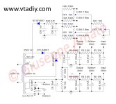
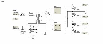
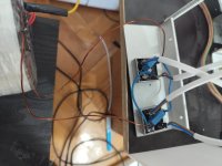
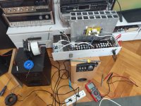
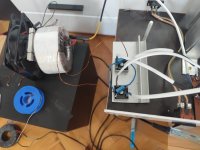
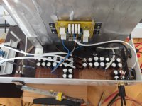
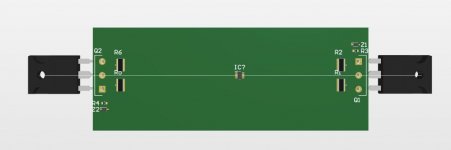
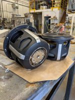
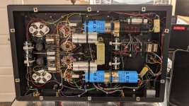
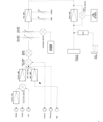
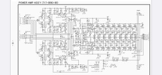
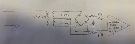
So, hey guys, Im still in the testing and prototypeing phase but i finally finished testing all power source solutions for my Aleph-3 build. The best configuration that makes this amplifier sound absolutely magical is one transformer, two rectifiers, and two capacitor banks. This type of Class A amplifier is incredibly influenced by the power supply, and you can wire it in the most common three ways:
1.A single transformer, one rectifier, and a big capacitor bank: This setup will give you the worst bass possible, a very flat center image, no layering, and absolutely no body in the sound.
2.Two transformers, two rectifiers, two capacitor banks: This setup is very problematic because if one of the transformers is not on the same phase, the sound quality is absolutely gone, and it won't sound better than a cheap '80s or '90s amp. But if they are in phase, the sound quality is decent but not great. The soundstage is there but not precise, you can't pinpoint details, layering is really weak, and the body is still missing.
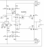
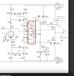
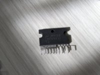
3.The overall WINNER: one transformer, two rectifiers, and two capacitor banks: This way, the sound is absolutely magical. Precise, pinpoint accurate imaging, fabulous layering, and incredible body to all sounds. It simply becomes that amp that you can't turn off. This configuration also has some downsides: the rectifiers get hot, and the transformer needs to be big. Oh, and under no circumstances should you use a CLC or CRC filter in this configuration. I find it pointless and, in some songs, it ruins the guitar sound magic (e.g., Buckethead songs).I can go into more details, but if you are a real DIY person at the beginning of building one of these, just do it as I say and be amazed. Of course for the final build I will use super fast diodes and decent capacitors .Any comments are greatly appreciated. Peace!

Attachments

  • IMG-20240630-WA0001.jpg
    IMG-20240630-WA0001.jpg
    18.2 KB · Views: 295
  • IMG_20240715_180124.jpg
    IMG_20240715_180124.jpg
    294.5 KB · Views: 262
  • IMG_20240715_180116.jpg
    IMG_20240715_180116.jpg
    462.1 KB · Views: 214
  • IMG_20240715_180108.jpg
    IMG_20240715_180108.jpg
    278.2 KB · Views: 222
  • IMG_20240715_180104.jpg
    IMG_20240715_180104.jpg
    364.2 KB · Views: 280
  • Like
Reactions: hbtaudio and Logon

NAD C165 potentiometer 4th tap solutions

Hello,

Some time ago changed NAD C165 pre-amp Volume potentiometer. As always, affordable potentiometer was standard with 3 taps. Original potentiometer has 4th tap. After the replacement Tone control is not working.

Has anyone found a custom solution for simulating 4th tap? Not expecting the full operation only to get Tone controls back to working at some level.

Nad_c165_pot.png

Problem miniDSP/Sure + Powersoft DigiMod

Hi everyone, I have a mini dsp that I want to use to bi-amp some speakers. I have some powersoft digimod 1000 and 500 that can be used both unbalanced and balanced, but the output level of the Mini dsp with an RCA connector is too low in terms of volume to be able to drive the amplifier. I tried some adau modules from sure and the result is the same. Where can I buy a PCB that acts as a preamplifier between the DSP and the amplifier? AliExpress? How should I search? Do you have any links? Thanks

The marriage

Hello guys,

I`ve been dreaming for a long time on a nice balanced preamp that can drive directly a power follower.
Lately @Zen Mod offered both the nice preamp, the Iron Pre, and also a lot of power followers from which one in particular caught my attention and that is Plethora of Pinjatas .
Slowly but steady I managed to draw a pcb for the IP and mount it in my UGS Pre, obviously the idea was implemented with the help of Zen Mod.
Now I want to start drawing the pcb(s) with the OS of Plethora of Pinjatas but not being sure if it`s going to work I asked Zen Mod about it and on his advice I started this thread.
So again slowly(I have close to 10 years since I dream about this) I started to copy the schematic of Plethora of Pinjatas OS and to make the pcb.

To mention that the dimension between the holes of the mosfets in my case is 15cm, I don`t use the standard UMS.

If I got it right I need 2x OSes, to the input of the first OS(R125) I will connect the positive output of the preamp and to the input of the second OS(R125) I will connect the negative output of the preamp. From the positive OS I will take the + signal for the speaker, from the negative OS I will take the - signal for the speaker, correct?

Now how can I adjust the offset? Is it ok to use same config as Sissysit 42? What will happen if I have the preamp dc coupled and the input of the OS(R125) is not at 0V?

Attachments

  • Screenshot_10.jpg
    Screenshot_10.jpg
    20.9 KB · Views: 913
  • Screenshot_11.jpg
    Screenshot_11.jpg
    82.5 KB · Views: 888
  • Screenshot_12.jpg
    Screenshot_12.jpg
    67.7 KB · Views: 1,032
  • Screenshot_13.jpg
    Screenshot_13.jpg
    59.5 KB · Views: 1,042

Max X sealed questions

Has anyone modeled or played with the 15” Dayton Max X in a sealed enclosure for mobile applications?

It has some good max, so I’m hoping to go a little bigger than suggested in order to take advantage of the xmax and increase low end extension.


Overall, it’s for an old-school build that will have a Power 300 MOSFET of the fronts and likely use a Zeus to push the Max X. I can feed it anywhere from 600-900 rms with other amplifiers if needed.


https://www.parts-express.com/Dayto...SD_-QTCyNbXIOj2bQain7rz_FHLef0tWvrMkTi8Le46Bg

ClarytyHD Model 1 Power block : HYS3C300-CS, Varistor (VR1) destroyed

Hi everyone,
This is my first thread and here are few words to introduce myself. I consider myself equiped with only some theoretical knowledge in electronics as I thought courses in General Physics for many years.
I got a ClarytyHD Model 1 and the varistor (VR 1) in my power block HYS3C300-CS has been destroyed and no specifications can be retrieved. ( it is on the right side of 4 rectifier diodes)
Did many attempts to get schematics for ClarytyHD Model 1 but without success .
Does anyone know the specs of the varistor so I can replace it? I found this image in diyaudio forum so mine looks exactly the same.
Any help is appreciated.
Thanks

Attachments

  • image.jpeg
    image.jpeg
    346.6 KB · Views: 122

SB Acoustics 3 way active build - Advice

Hi All,

I think I'm going to dive in head first and work towards a great set of Active 3 ways.
I'm going to run a Hypex Fa123/253 depending on power needs.

I've been doing a heap of reading and have come up with the following options.

Tweeter - TW29BN/TW29R-B/TW29TXN-B
Mids - MR16P/MW19P/MW16TX/MW19TX
Bass - SB34NRXL75-8/ Any other suggestions here?

What are your thoughts on these options/combos?
Also when running the Hypex amps, is there a preference on which Ohm version of the speaker you should use?

Throw as much advice my way as you can, keen to start purchasing parts 🙂

PC desk subwoofer using car audio drivers

Hey guys

I recently moved from my little apartment to a nice big house and I have been working on setting up a nice computer desk with some decent audio for gaming and music. I currently use a pair of KEF Q15 speakers on a small Fosi Audio V3 class D amplifier, these speakers sound pretty nice but they have very little bass to speak of.

I have a pair of Hertz ML2500 10" subwoofers leftover from my car audio days and was considering sticking them in a nice Acadia Wood box to match my desk. Way back when these were really expensive drivers and were considered top of the line so it would be nice if I could repurpose them assuming they'll work well in the application.

I managed to find what I believe is the correct TS parameters on an old forum post and ran a quick model in WinISD with a 1.5 cubic foot sealed box that looked pretty good. These are good looking drivers and it would be nice if I could put them to good use.

Attachments

  • mille ts parameters.jpg
    mille ts parameters.jpg
    52 KB · Views: 89
  • PXL_20210707_191914937.jpg
    PXL_20210707_191914937.jpg
    577.9 KB · Views: 94
  • PXL_20210707_191918374.jpg
    PXL_20210707_191918374.jpg
    454.6 KB · Views: 87
  • PXL_20210707_192303318.jpg
    PXL_20210707_192303318.jpg
    463.4 KB · Views: 88
  • Like
Reactions: stv

Okto Research DAC8 PRO and DAC8 Stereo

dac8stereo_front_d.jpg


dac8 PRO: 8-channel D/A converter with top-tier analog performance. USB and 4x AES/EBU inputs.


dac8 Stereo: highest performance, streaming-enabled stereo D/A converter. USB, 2x SPDIF, 2x Toslink, AES/EBU inputs. Streaming over Ethernet and Wi-Fi through the integrated Raspberry Pi 4.

Read the dac8 Stereo launch newsletter here


"dac8 Stereo is a result of many years of our pursuit to get the most from the flagship Sabre D/A chips. While it shares the analog architecture with the dac8 PRO, the dac8 Stereo combines 4+4 channels to double the dynamic range and push the measured performance to the levels thought to be unattainable. It also adds Raspberry Pi 4 on top, a widely accepted, community-supported single board computer that enables it to play audio from network storage or streaming services.

In our design process, we ended up diverging completely from the D/A chip manufacturer guidelines. The main idea behind the products is that, ultimately, it is the implementation that creates the performance and character."


Pavel, Okto Research
www.oktoresearch.com
info@oktoresearch.com

Getting mail with someone else name but my address

Over the last month we've gotten two pieces of mail with someone else name but our address. The first one appeared to be a check from a company and the latest is a check from Social Security visible through the address window. I didn't think much about it on the first one and just wrote "Person not at this address", dropped it back in the mail and forgot about it. I don't remember if the names on both were the same. Our address is quite unique so it isn't someone mistaking street for drive or something like that. And prior to us living here it was an orchard.

Has anyone ever heard of anything like this?

An interesting side not is both times we received one of these our camera showed someone coming to the door in the middle of the day and impatiently ringing the bell and knocking. The first time was a guy and the second was a woman. Neither appeared to be selling anything, both were dressed some what sloppy and both drove specifically to our house and then left so they weren't going door to door. I didn't save the camera footage the first time so I don't know if it was the same car.

I think I'll take this one into the local social security office on Monday, but I'm not expecting much of a response. I did a search and found there are scams where they mix names, addresses and ss#'s to create new identities but someone is getting checks sent, which is odd.

Chadwick executive monitor need information for restoration ...help please

hi .. im looking for photos or any information on the Australian made Chadwick audio speakers .The model is Executive Monitor Made around the 80's Sometime.
I recently acquired a pair with the woofers missing ... does anyone have photos or any helpful info on them eg tweeter and midrange models and numbers .Apparently the woofers are modified Etone 245 ,any photos or information would be great as i dont know if any of the drivers are original or not. At the moment i have put in a pair of no name woofers in them and they sound really nice but i do want to put the original woofers in if i find a pair. Hopefully I am going to restore them back to original if i can get all the info ..please help

Fake Toshiba 2sk2013/2SJ313?

I bought 2sk2013/2sj313 at yahoo auction just now but found some fake news here.

I saw seller's fet analysis but 2sk2013's Vgs-id looks weird.

2SK2013:Vgs = 1.782~1.970V Id = 5.00~5.05mA
2SJ313: Vgs = 4.029~4.256V Id = 4.95~4.98mA

From datasheet,2sk2013's VHS must be around 2.5v.
And photo.
I might cancel my bid, could someone advice me if I am saying right or not?
Sorry for noob question.

Attachments

  • Screenshot_20240701-230540.png
    Screenshot_20240701-230540.png
    220.8 KB · Views: 184
  • Screenshot_20240701-230543.png
    Screenshot_20240701-230543.png
    216.9 KB · Views: 176

Woodside Electronics SET-30 - Help!

I have an unusual Woodside triode power amplifier that started blowing fuse a while back. I put it away for 10 years and recently came across it in a move and would like to get it operating again. When it did run it was the best sounding amplifier I’ve ever heard, other than my even older Futterman OTL’s.

The company, while quite helpful, didn’t have much information as only a handful were made long ago. I have a TV-7D/U tube tester and a multimeter, and am pretty good with a soldering iron. I’ll begin by testing the signal tubes, but I have no parameters for the output tubes for my TV-7. The filaments have continuity.

I’m told the amp draws 4 amps from the power transformer… I hope it’s not shot.

Where should I begin after testing the tubes?
1000001916.jpg

Attachments

  • 1000001917.jpg
    1000001917.jpg
    363.2 KB · Views: 259

Characterising a tube

Hello!
I hope you guys do not mind me picking your brain once more. I got a bunch of NOS/used tubes, mostly television ones. I do not have a tube tester (planning to make a simple one, but that's way ahead), and I was wondering if I can just use a simple circuit to characterise the tubes and finding matched ones. I have been testing double triodes in a common cathode circuit, and the measurement is pretty consistent with datasheet curves and simulations when the tubes are good.

Q1: Is this a good approach for tube testing and matching in the absence of a proper tube tester?
Q2: For testing a power triode-pentode (E/PCL8x), would you test then with an output transformer, like a real SE circuit? or just best keep it simple, using a resistor as a load?

Regards,
Jose

Tube amp for power hungry planar magnetics

Hello everybody,
Hope you are doing well!
I have a pair of audezee lcd3 headphones and I’m looking to build a tube amp for them. It can be both with an output transformer as well as Otl. I’m looking for some thing high quality with a great sound. The headphones have an impendance of around 100 Ohm and as all planar magnetics are relatively power hungry. Any suggestions or direct experiences? I’ve searched the net but so far didn’t find anything that has convinced me 100%.

Thank you very much!

Matched 2SJ109V + 2SK389V on ebay.

Im now selling IDSS matched 2SJ109V + 2SK389V pairs on ebay. ID was measured at VDS=10V and VGS = 0V. Parts are matched to be within 100uA on each side. Measurements were taken with an old hameg curve tracer.

ID values are mostly between 11 and 17.5mA. If you want a particular value send me message on ebay and i will let you know the closest pair that i have.

I have only measured 20% of the FETs that i have and am open to suggestions if anyone thinks my matching method can be improved on.

These are genuine Toshiba parts and my seller feedback will confirm that i am not selling fakes.

https://www.ebay.com/usr/jsaarl

“JMC800 micro" output tube options

Hello:
I am hoping to build the noted amp as designed by RobRobinette. He does 2 designs one with 12au7(1W) one with ef80(2W) as the output stage tubes. I am looking for a bit more than 1 Watt output and I do not have any ef80 tubes. Has anyone done a similar pentode pushpull design with other output tubes. I am looking for output in the 1,2,3W range. I have a Hammond 125b output transformer.

Thanks for the help and discussion.

Crimson (Krimson) Amp Schematics

Hello everyone. I have come across two old amplifiers from Crimson that were put together from kits in the mid 80's. The one is 60W and the other a 100W. I believe the models are 608 and 1008 respectively. The transistors used are both Toshiba, 2N3773 and 2N3055 respectively.

I would like to get these guys running, does anyone have any info/schematics on these? Thank you in advance.

Clipping light comes on too early

Hello, my brother has a minor issue with his amplifier (ural warhead 1.1800), the clipping light on the remote comes on, but the sub doesn't get hot and doesn't sound weird. What could be faulty? IIRC there should be a comparator comparing the rail and output voltage, right?

Not planning on fixing it any time soon, just wanna know which component could be faulty.

GB: SDTrans384 - A micro SD card digital transport

Sept 25, 2015
A new batch is now available, same pricing & quantity discounts applied. Please contact Mr. Yamazaki directly if interested. 🙂
-----

Yamazaki san of Tachyon Limited is delighted to offer a group buy opportunity for the SDTrans384.

1) About the unit

SDTrans384 - a micro SD card digital transport:
http://www.diyaudio.com/forums/digital-source/142562-microsd-memory-card-transport-project-50.html

Description of the last batch on Tachyon's site.
Notice that you could specify the choice of display color.
Tachyon - SDTrans384

(Google translate)
https://translate.googleusercontent...4.html&usg=ALkJrhikiE9UavuOMsSVRrVupkMbUO6WWw

2) Details of the GB:

SDTrans384 .... JPY 49,800
SDTrans384 (with remote control) .... JPY 59,600
(USD1 = JPY102.6 as of Aug 14, 2014)

1-4pcs ...no discount
5pcs ... 5% off
10pcs ...10% off
20pcs …15% off
(over 20pcs reached , discount is now 20%)

3) Payment and shipping

Buyer to pay half of the total amount when ordering and remit the remaining balance at time of shipping.
Will take 1 to 2 months to manufacture the SDTrans384 units after receiving the group order.

Please indicate your interest here **AND MUST** also send a reservation email to Yamazaki san for the exact pricing and shipping information to your location. (His email address is sichoya <at> yahoo <dot> co.jp)

***For technical information and discussion please refer to the following thread***
http://www.diyaudio.com/forums/digital-source/142562-microsd-memory-card-transport-project-66.html

Akabak problem

Hello everyone,

I've been working on an akabak project for a subwoofer speaker box. I have been guided by tutorials.

I already made the entire model, but I don't know how to simulate its response. In the video I watched, I clicked on "Starts all specified simulations" and after doing the process, in the "messages" section it tells me that I have errors.
Initially it threw me some errors that I was able to fix, but now it's throwing me new ones that I don't understand.

If anyone can help me with this it would be very helpful. I am attaching the akabak file here.

Attachments

Yamaha AX-500 amp

My venerable AX-500 is a bit under the weather. It used to take a couple of seconds for the amp to "click" and switch the speakers on, in the past couple of days is has gone weak on the left hand channel. It does still work, but at a much lower volume. I have used different inputs, the B speakers and swapped left / right on the speakers and the problem remains

Suspecting blown caps I have taken the top off and taken a photo. The 12000 uF capacitors have been dusted clean, the rest of the board blown clean. It appears that the rear capacitor has been leaking and indeed the top of it is slightly convex. The smaller 470uF capacitor is not bulging, but the different colour around its base suggests to me that that has been leaking too.

Could someone confirm the diagnosis, suggest any further tests to be done, or even a place to get suitable replacement components - the main caps are nichicon 85 degree

IMAG1327.jpg

Big coaxial with RCF CX12N251

I 'll make a pair of active dsp-controlled floorstanders, big and loud this time! Speakers will be made with my heavy metal fan son, for indoor home listening.

https://en.toutlehautparleur.com/coaxial-speaker-rcf-cx12n251-8-8-ohm-12-6-inch.html
a pair of 12" woofers, closed box, xo around 200Hz
Hypex FA123

I found these pro coaxials at THLP, I was searching for ones with a fixed horn. I couldn't find directivity or any other independent measurements, so going blind this time! More detailed plans during Christmas holidays and first measurements in test baffle in January!

Here is link to photo album of the project https://photos.app.goo.gl/hGFkqajgoVwWrzL59


1671040549698.png

Hi there!

Hi,

I'm from France, and i'm interested in repairing/modding/hacking various stuff, including audio devices.

At the moment i'm trying to restore some cassette (Nakamichi 480Z, Tascam 322) and reel to reel decks (Pioneer RT-909, Teac A3440). I'm also trying to find a fix to a cross-talk problem i've just discovered with Behringer UCA222 USB audio interface, and i've discovered a post here just about that and wanted to discuss about it (it is an old post from 2020, but since UCA222 is still sold at this time, can be interesting for others too).

Never knew this forum before, so freshly registered 🙂

For Sale LME49830, LME49811, Burson V6 Vivid Single, Dual

I am selling:

6x LME49830 - 50 euro/pair
2x LME49811 - 30 euro both
2x BURSON V6 VIVID SINGLE - 50 euro both or 70 euro with V6 DUAL
1X BURSON V6 VIVID DUAL - 30 euro


LME49830
and LME49811 are directly from National Semiconductor and the Burson V6 opamps were never used.
I ship only in EU, the shipping cost is 15 euro.
Thanks!

Attachments

  • PXL_20240511_134741647.jpg
    PXL_20240511_134741647.jpg
    607.7 KB · Views: 85
  • PXL_20240511_134917008.jpg
    PXL_20240511_134917008.jpg
    680.7 KB · Views: 75
  • PXL_20240511_135002480.jpg
    PXL_20240511_135002480.jpg
    302.5 KB · Views: 73
  • PXL_20240511_135010957.jpg
    PXL_20240511_135010957.jpg
    304.5 KB · Views: 81
  • PXL_20240511_135040637.jpg
    PXL_20240511_135040637.jpg
    216.6 KB · Views: 80
  • PXL_20240511_135048252.jpg
    PXL_20240511_135048252.jpg
    256.2 KB · Views: 87
  • PXL_20240511_135107844.jpg
    PXL_20240511_135107844.jpg
    317.1 KB · Views: 79
  • PXL_20240511_135154276.jpg
    PXL_20240511_135154276.jpg
    329.5 KB · Views: 81
  • PXL_20240511_140018015.jpg
    PXL_20240511_140018015.jpg
    294.4 KB · Views: 79

Datasheet or description with Hammond PTs?

I'm looking at some Hammond transformers that are all described as 325-0-325V or 650VCT at 170-180 ma for a 300B build (Tubelab TSE-II, 5k outputs, seeking just under 400V B+ on US line voltage with maybe a 70-80 ohm choke, like a 193J).

Candidates include the 273CZ, 290CX, and 260J. Am I right to assume that I'd get very different voltages out of these even though they are all described similarly in the top line specs? Under the "electrical data" on the spec sheet the 273CZ shows 686.6V with a 125V input. The 260J shows 701V with only 120V. The 290CX shows a whopping 714V on only 120V. (All 60hz.)

The DCRs of the secondaries also get significantly lower in the order of ascending voltage. They are different weights, ranging from the 260J at 5 lbs to the 290CX at 6.8 lbs. The 260J has an amp less capacity on the 5V winding that I'd often think may cause it to sag a bit more if all are loaded the same, but because it is a much newer design and the primary set up is more like the 300 series than the 200 series, I'm not so sure. I haven't run anything through PSUD or another simulator.

I'm contemplating giving the 260J a shot for packaging reasons (under a cheap auction site cover). But one gets a lot more iron for the money with the 290CX (like $30-40 cheaper than the other two), presumably because of economies of scale related to guitar things. I'm tempted by it, but a little worried that I'd end up with more B+ that I'm looking for.

Regardless of my circumstances, unless there is something I don't know about how to interpret these datasheets, one needs to look a bit closer at the actual measurements to be sure of what they are getting with Hammond.

Paul

Marantz PM-30 (1978) aka A-530 low output level

I've picked up a cosmetically nice Marantz PM-30, which is the same as the A-530 and Superscope BLA-530 and almost the same as the 1050.

Everything works (balance, treble, all inputs etc), but the output level is very low, turning the volume knob to about 3/4 provides a listenable signal, but lacking some punch.

It has never been touched inside (one owner apparently) and not used for 20 years. I've cleaned all the pots, even though they weren't scratchy at all.

I found a manual and started measuring, then decided to take out the filter caps to replace them, and now realise I can't do any more measurements until I get new caps.

The 6800uF caps measured at just under 5000uF, under spec but I think should have still been enough for the amp to function.

Given all functions work, I figure it has to be something common but I'm finding the schematic hard to follow. there are some voltages listed in the manual though, and they are out of spec in several parts. I can/will pull out the components to test, but wondering if this points to c804 having a problem? Red/yellow values are what I found in different manuals, black is what I measured.

Also lots of incorrect values around Q403 but that may be downstream from this issue and I guess is only one channel?

IMG_9428.jpg

Attachments

  • PM-30 Circuit Diagram.png
    PM-30 Circuit Diagram.png
    118.4 KB · Views: 115
  • PM-30 q403.png
    PM-30 q403.png
    163.4 KB · Views: 82
  • PM-30 schematic.png
    PM-30 schematic.png
    31.1 KB · Views: 103

Accuphase M6000

Accuphase M-6000, a MOSFET class AB amplifier made between 2008 and 2015.

On its prospectus it said A damping factor rating of more than 500 demonstrates that this amplifier is capable of driving even the most difficult, ultra-low impedance loads with ease.

Weighing in at 38kg, and Continuous Average Output 1,200 watts into 1 ohm (✽)
600 watts into 2 ohms
300 watts into 4 ohms
150 watts into 8 ohms
  • Two totally identical power amplifier circuits driven in parallel
  • 16 parallel push-pull arrangement of MOS-FET devices in output stage
  • Input stage configured as double instrumentation amplifier
  • Double MCS+ circuit and current feedback topology in amplification stage
  • Support for bridged use of two M-6000 units with even higher output power
  • Power supply with massive high-efficiency 900-VA toroidal transformer and large filtering capacitors
When I googled a week ago I couldn’t find any in-depth review. Probably not too popular.

I wonder how it sounds compared to the Pass labs A5.

Attachments

  • IMG_3090.jpeg
    IMG_3090.jpeg
    37.5 KB · Views: 204
  • IMG_3091.jpeg
    IMG_3091.jpeg
    51.6 KB · Views: 126
  • IMG_3092.jpeg
    IMG_3092.jpeg
    34.1 KB · Views: 206
  • IMG_2889.png
    IMG_2889.png
    282 KB · Views: 224

Roon alternative?

Buyer beware. If you are considering roon, know that it will no longer allow you to access your bought and paid for local music files without an Internet connection. This “improvement” came about with version 2.0. During a recent Internet outage my $50,000 plus audio system became a worthless steaming pile of crap. With the Internet down, I could not even listen to my local files.

Maybe you are OK with allowing an outside company to hold your local files and expensive audio gear hostage. I’m not. Not even for a moment.
just my humble opinion

hoping someone can direct me to a program or method by which I can access my local music files without an Internet connection

Vanguard Speaker

I’m pleased to announce that the Vanguard speaker, an modern take on the classic British bookshelf monitor but with a bolder and presentation will be nearing completing manufacturing soon. It will be released under a new brand called eXtremely Sexy Audio (XSA) Labs, a subsidiary of Vera-Fi Audio, LLC.

Due to the war in Ukraine and embargo on Russia, Baltic birch is not available so the first batch will be in all bamboo.

1657581707977.jpeg

1657581844167.jpeg

1657581863507.jpeg

1657581879490.jpeg

1657581897737.jpeg


Next to a Graham Chartwell LS3/5A.

1657581943477.jpeg
Measures 7.5in W x 12in H x 8in D. 50W 83dB at 2.83v. True 8ohm impedance. Introductory price will be $799 for first 25 sets.

DVD 5000 with four PCM 1704 DACs

Up for sale is a DENON DVD 5000. This DVD player is famous for its use R2R DAC Burr Brown PCM1704. This is last know greatest R2R DAC chip period. This DVD Player has four of them. Not to mentioned four great OP275 opamp used with it. I used it only as DAC (it has SPDIF and optical input. Line output and also variable output). This DVD player is very heavy due of copper chassis (extremely stable ground plane). I opened the cover and lost few screws. The cover is not it greatest shape, but the it worked great for me until I bought a new Denafrips DAC. This can used used as spare DAC or use four PCM1704 DAC chips for audio projects. Not to mention four OP275 and two NE5532 (Phillips made). Also there are two high quality transformers that can be used for project. This DVD player is very heavy and cannot be shipped (only local pickup) or I can ship the top board which contains all mentioned ICs in anti static bag.

Last time I, tested it played Audio CD quite well. After that I have used it only as DAC.

Price is $200 or OBO and Local Pickup(Chicago area) for whole DVD player. if you want to me ship just the board then shipping cost withing US is $16 and for rest of world is $50. I still prefer to sell locally.

Attachments

  • _IMG0655.jpg
    _IMG0655.jpg
    608.7 KB · Views: 668
  • _IMG0664.jpg
    _IMG0664.jpg
    747.6 KB · Views: 652
  • _IMG0669.jpg
    _IMG0669.jpg
    952 KB · Views: 806

Mtx 7801

I have a mtx 7801 amp
I was running the amp off stock alt and voltage dropped low, below 10v
Amp shut off. I recently decided to take a look at the amp to try my hand at repair but am lost on where to start testing. An mtx tech said to start testing the fets off the heatsink.
I found a fourm on an mtx 8001 and found an image attached that matches what someone else did to my amp. I dont know the purpose, it looks like a cap in line with the fet, im guessing its been replaced and this is to ensure proper voltage, but i could use some clarification and instuction on testing and repair.

Need help while designing my practice amp

Hello everyone i am just a newbie both for this forum and for DIY electronics. My experience is limited to soldering guitar cables and building one amp for home which I found the diagram from a random website. It was just do whatever you see and do not question things kind of experience.

Normally I build lots of acoustic instruments but this time I want to build something different for myself so i builded multiscale ashbory style bass. It is the first electric instrument that I built. For this little and weird instrument now I want to build a little and weird practice amp.

My main idea is modify the diagram of the model t preamp diagram and turn it into a practice amp. But with my lack of knowledge (maybe ignorance) I could not figure out how I could modify this diagram and build the final product.

The challenges for this project:
The amp will drive the 4ohm 3W exciter,
It should be suitable for bass guitar and
I want to use saturable reactors as a gain component.

Basically i do not know how to set the output for 4ohm 3W. I know I need to select input and output capacitors a little bigger for making it bass guitar friendly but is there anything else that I need to tweek? Last but not least is it a stupid idea to try to create an amp based on a preamp circuit?

I shared the diagram for the Sunn Model T preamp that I want to modify. I will be so glad if someone can help me with this project.

Best Regards

Attachments

  • Sunn Model T Preamp V2.png
    Sunn Model T Preamp V2.png
    67.9 KB · Views: 133
  • Sunn Model T Preamp.png
    Sunn Model T Preamp.png
    66.9 KB · Views: 137

Moin@All

Hello, I'm Peter, spending my life besides work as a seeker. So far, so normally. I'm owing a pair of Celestion's Ditton 66 of the early generation, with the complete MF500 placement. Being young, the "studio monis" had to be punished on each party I joined, and there were many of them. So the lower acceptable power MF500 quitted often. At that time Celestion offered complete mounted Diaphragms to be built in, no way of mistakes possible so as centering the coil to the magnet, as I'm expierencing today, with a repairkit made in France by Ninomusic France, sold in the bay. The cork spacers couldn't be saved during changing the dia, and now you're facing the centering problem, becaus of many distances of each part of the sandwich. And, what I'm presuming by the way is the fact of smaller dias in the MD500, so not compareable with the MF500 magnet and diffusor. I'm disappointed at the mo, but not willing of giving it up! With a little help of yours it'll be succeed!
If not, is there anybody selling especially to me a complete MD500? Is there anybody laughing?
Yours sincerely, Peter
PS: I forgot saying something about me, whom I living in the land between the seas: Schleswig-Holstein, northern Germany area, 80KM lower than Denmark. This "Moin" is typically for the people's daily greetings to eachother, my nicknameputs two words together, adding and Zen, my japanese sight on things and phenomenons.

Help needed for an Amplifier repair

Hey all,
I'm trying to repair a friends Amp that refuses to power up.
I've narrowed it down to the power supply section of the Microcontroller.
I've replaced transistors Q1-Q3 (MPSA55) and Q2-Q4 (MPSA05) and the U32 (L4940V5) which is a Fixed 5volt LDO Regulator with a Zener (D14) added at the Ground PIN to output 5.6volt.
Need some help to identify the two Zener Diodes D4 and D14.
K1 (High Voltage Relay) is 12volt.
Thanks in advance.

Attachments

  • 20240802_165544.jpg
    20240802_165544.jpg
    413.9 KB · Views: 103
  • 20240802_165609.jpg
    20240802_165609.jpg
    405.2 KB · Views: 106
  • untitled.JPG
    untitled.JPG
    200.4 KB · Views: 97
  • untitled2.JPG
    untitled2.JPG
    145.3 KB · Views: 89

Linear Power Supply Design

I have the Arcam rDac, which has a 6V 600mA power requirement.
I have been running the DAC with the supplied SMPS wall wart, as well as a second wall wart. Both power supplies give off a reasonably loud high frequency noise, and I'd like to build a dedicated Linear Power Supply. Similar to something like this but within a reasonable price range.
I've got a bit of electronics experience, having built/tweaked elekit amplifiers, but would like to get input/advice on the circuit I've planned for the power supply.

Are there any further improvements that could be made to the design (such as a low-noise regulator), which would be worthwhile?

export.png


Appreciating any and all feedback!

What does this calculator mean?

I found an online calculator of box resonances. It’s easy to use, simply fill the speaker cabinet dimension and it will return results.

Picture is the result of my speaker’s dimension inputted.

IMG_8793.jpeg


Unfortunately, I don’t understand what they mean. Could anyone please explain the results for me?

Also, according to the results, which frequencies could cause the mid-bass boom phenomenon?

Link to the calculator: https://web.archive.org/web/20230603010703/http://www.mh-audio.nl/Calculators/standingwaveinbox.html

Best Enclosure Design for Faital Pro 18FH500

I'm going to build loudspeaker like Dynamikks Monitor 12.18.
There are two Faital Pro 18FH500 in the boxes waiting 🙂
Crossover about 100Hz (passive).
First idea was bass-reflex (200dm3/8ft3) with bigger ports but maybe it is better enclosure for 18FH500? I want quick low bass. Loudspeaker must be placement near the wall.
I don't know if 18FH500 are compatible with Onken (can't find any easy to use calculator).

Android Apps for measurements of loudspeakers

Are there any android apps for measuring loudspeakers?

Be it for free or for money?

I can use a smartfone as source and another one for measuring frequency response and waterfalls.

Distortion is not necessary.

Implemented microphones should be enough linear in the mids where it is most important.

Highs and lows are always adjusted to taste.

The most important region is 200hz to 8khz.

Even if integrated mic deviates outside of this band I will find that easily out measuring well known responses from existing drivers.

I can tell that "Spectroid" is a good tool for getting an impression for frequency response but it is not ideal.

Also you can download white and pink noise signals from YouTube and extract the audio. If you look for "YouTube to mp3 converter" you find the tools online.

Who knows more?

Which apps will do?

Newform Research R630 ribbon project

SOLD

For more info see the build thread here https://www.diyaudio.com/community/threads/abandoned-project-2-newform-r630-ribbon-system.415847/

2 ea Newform Research R30 ribbon drivers $475/pr 46 lb (still available new for $1042/pr https://www.newformresearch.com/index.php/products/our-models/bare-ribbons/r30 ) Shipped in original packaging

2 ea ScanSpeak 18W/8545K (open coils) $30/pr 9.2 lb

2 ea Newform XO’s for above free + shipping 1.5 lb

2 ea Cabinets free + shipping 18 lb

Free pickup in Mountain View, CA 94043

All offers considered

Packaging materials will add to weight & shipping cost

Full-resolution photos: https://photos.app.goo.gl/3HCg7vEm13SYJuWv5

If you google reviews for Newform Ribbons I believe you'll find that the consensus is that these are high end drivers; IIRC the odd less-than-glowing response is likely due to the woofer paired with it.

https://www.google.com/search?q=newform+research+ribbon+reviews&newwindow=1&sca_esv=08a7c6c574dce941&sca_upv=1&sxsrf=ADLYWIKxVt-Dsize8UPuzYIlgV-aFvKfvw:1722629125517&ei=BTytZtmeH5fMkPIP4NTUyAY&ved=0ahUKEwiZtezIjdeHAxUXJkQIHWAqFWkQ4dUDCBA&uact=5&oq=newform+research+ribbon+reviews&gs_lp=Egxnd3Mtd2l6LXNlcnAiH25ld2Zvcm0gcmVzZWFyY2ggcmliYm9uIHJldmlld3MyCBAAGIAEGKIEMggQABiABBiiBDIIEAAYgAQYogQyCBAAGIAEGKIESONKULEJWLUkcAF4AJABAJgBe6ABtQSqAQMwLjW4AQPIAQD4AQGYAgWgArwEwgIIECEYoAEYwwTCAggQABiiBBiJBcICChAhGKABGMMEGAqYAwCIBgGSBwMwLjWgB80M&sclient=gws-wiz-serp

R30ad-1.jpg
R30ad-2.jpg
R30ad-3.jpg
R30ad-4.jpg
R30ad-5.jpg
R30ad-6.jpg
  • Like
Reactions: taloyd

Abandoned project #2 - Newform R630 ribbon system

Full story below, but to cut to the chase these are now up for sale in the classifieds https://www.diyaudio.com/community/threads/newform-research-r630-ribbon-project.415849/

Originally, I built these using Newform Research R630 components: R30 ribbons and ScanSpeak 18W/8545K woofers, and Newform-built crossovers and put them in solid maple sealed boxes I made [I was having trouble inserting pictures within the text, so the rest is screen captures]

R30-1.jpg
R30-2.jpg
R30-3.jpg
R30-4.jpg

Abandoned project #1 - Full HT system w/Linaeum, Focal, and Morel

This is the first of three build threads on speaker projects which I’m bailing out on; it’s now listed in the classifieds https://www.diyaudio.com/community/...l-rs-radio-shack-linaeum.415846/#post-7752390

The backstory in case you’re wondering:

I ran out of motivation to finish these after putting in way more time than I had anticipated.

And in the meantime my hearing has degraded to where I can only hear up to 8 kHz, so the pristine treble is wasted on me.

I haven’t worked on this writeup up since last November and at this point it’s too much like homework, so the flow and organization may not be that great.

This project is/was line array fronts, bipolar side surrounds, monopole back surrounds, and a pair of subs (left side shown).

I was having trouble inserting pictures within the text, so the rest is screen captures.

surr-01.jpg
surr-02.jpg
surr-03.jpg
surr-04.jpg
surr-05.jpg
surr-06.jpg
surr-07.jpg
surr-08.jpg
surr-09.jpg
surr-10.jpg
surr-11.jpg
surr-12.jpg
surr-13.jpg

DSP to replace subwoofer servo control?

Is there an existing way to use a mic to measure a woofer's performance and then develop some DSP filters to correct for under/over-shoot of the cone at various volume levels?

I've been thinking about the servo feedback for subwoofers and it seems like with a mic we can build a model of each woofer's performance across the FR and at different volumes and adjust the signal preemptively to compensate for its issues. No need for a live feedback loop. Could apply to mids as well.

By amplifying the signal in the right way at the right times there would be much less need to carefully choose the right Qms, Qes, Qts, Mms of woofers. Any reasonable speaker could get pretty close to perfect cone control, all without a live feedback loop.

Suggest a Tube HiFi to build

Hi all, I have a made handful of tube guitar amps and now have my sights on a tube stereo project.

Are there schematics available online and where does one find them?
I don't need a kit, I can source just about everything.

Do you have suggestions for something excellent I could look into for DIY?
I realize there are differences in Class A vs A/B and tube types, etc. 300B or KT88 maybe? Those seem to be in high regard for power anyway.

Thanks for your help!

Bass amp built in to guitar case

I was a bass player ages ago (lol, 25ish years?) and just recently ordered one for Father’s Day.

I’ve been a tinkerer forever and have been eyeballing all the lovely and inexpensive new gear out there now… class D amps, and inexpensive subs and DML speakers and all this fun stuff I never knew I needed. ;-p

I want to shove a 10-12” sub (or maybe a 4 8” ones?) into a slightly beefed up bass guitar case, along with a few hundred watts of Class D amp and with some of the Dayton audio exciters to use one of the panels as a flat panel speaker. Ideally it would also have an AC and DC option. It also hopefully holds the guitar when it’s not being used. ;-p The intent is to jam with friends, maybe getting a little rowdy but not bringing down the house.

Not asking for much? lol. Anyway, I’m still in the ideas stage and have a few guidance questions.

Which is likely to work best, a single larger sub or several smaller ones? The “Enclosure” volume is likely to be 1.75-2 cubic feet. But some at least will be padded/felt lined which will eat some space. 16x48x5 or 6-ish inches.

Layout wise I’m debating between smaller subs and/or full range speakers on either side of the neck firing to the “back” or bottom, or a larger shallow mount sub with the neck literally sitting on foam padding on the speaker magnet when the bass is stored. The mids I’m not as worried about space wise, but I’m planning to at least try a DML flat panel soloution and see how far I get.

There’s obviously a lot of challenges, not the least of which is designing for a poor “enclosure” and just physically figuring out where and what to fit in there. It also can’t be toooo heavy, and still needs to protect the guitar in travel. Let me know if I’m missing something obvious as to why it’s a total no-go.

So… TLDR if you were thinking of making a bass amp that is also a bass case would you pick multiple smaller drivers or one as big as you can manage? (Ignore mids for now.)

Fuse rating?

Hi!

Trying to build an amplifier around 70W@8 ohm, and 520W@1 ohm, with as many output MOSFET as the Aleph 1.2, or more if I have to, so that it can cope with speakers with low impedance. My current speakers are 6 ohm nominal and drop to less than 1.5 Ohm. I am an old man in a small apartment and do not usually listen to music at moderate level.

The rail voltage will be +-38V, transformers are 2500VA for each channel, may be overkilled but I like to be able to reuse it should I decide to build a larger amplifier.

It will have the usual thermistor to limit inrush current etc.

For Fuse 1, I will use a 10A slow blown fuse, pretty straight forward.

For Fuse 2 and 3,

At 1.5 Ohm, the speakers will draw max. 25A, but being the low efficiency SE Class A, the amplifier may draw 4-5 times as much so perhaps 100~125A.

Q1) should the fuses be located between the capacitors and the amplifier? Or between the transformer and rectifier? Each capacitor has a ripple current of 70A.

Q2) what value should they be? For rail voltage of +-38V, should it be

a) 2500VA/38dc=68A; or
b) 2500VA/28ac=88A; or
c) 2500VA/(38+38)=34A; or
d) 2500VA/(28+28)=44A

Q3) should they be fast blown or slow blown fuses?

Thank you.

Attachments

  • IMG_3088.jpeg
    IMG_3088.jpeg
    155.6 KB · Views: 55

New Tracer is coming

1652597812925.png


-----------------------2022/12/27 Update:-------------------------------------
All options no more available.

-----------------------2022/5/15 Update:-------------------------------------

2 Pre-Release Full-Assembled iTracer & 8X Expansion, Ready for USE!
PM me for details.


---------------------------------------------------------------------------------

Hi,

There is a new tracer developed by my friend, coming around.
iTracer will be her name.

"There are 5 free sample of programed MCU for evaluating, if you are able to make your on iteration of PCB, you can ask for MCU module for free.
Otherwise, you can wait for my PCB iteration which I am working with, yet it may take some time."


The iTracer is an intergrated curve tracing system consist of dedicated software program and proprietary hardware.
iTracer provides curves tracing, DUT matching, distortion analyzing, database managing of transistors.

More specifically, the iTacer is developed and intended for DIYers and Hobbyists,
to enhance their ability to make matched transistor pairs, manage them by database.

The new iTracer has the following features and specs:
//

Current-Voltage (I-V) plotting capability by Graphical UI program (Bundled, free for buyers)

Compatible with V-FET(SIT), BJT, J-FET, MOS-FET, Diode, SCR, Resistor, Thyristor, Regulators (ex.LM7815)
3 channels for DUT: B=G C=D E=S

Vc/Vd: up to +-40V
Ic/Id: up to 3A (updated on March.2022)

*8x Expansion Module, Auto measure a batch up to 8 pcs at ONCE!
*Aruduino Nano as MCU, pre-programmed before shipping.
*Dedicated Graphical Tracer Program with powerful math processing, enhancing transistor matching accuracy/efficiency.

*Quick FFT/Working point Analysis/Simulation based on measured data/curve at Realtime!
1650962142383.png


2SK79 Analysis:
1652597133521.png

//


*2022/5/15
Fully-Assembled iTracer + 8X EXPANSION, Ready for Use!

1652597301469.png


1652597236722.png


//
What features makes iTracer Unique?
Scenario happens usually:

For sure we can use curve tracers and plot traces of these 100 transistors, then compare the curves one by one.
If the plotted curves are close or overlapping, one may think: oh! These 2 transistors are the matched pair! Job done!


However, what we are thinking about is how close is enough to say they are matched?
Two derivative question raised:
1. Can we quantify "close"?
2. Is there better way for quicker, automatic measuring?


Hence, mathematical models and algorithms are developped for this tracer project:

1. The iTracer can measure a batch of DUTs up 8 pcs at once, automatically(by swithing relays).
2. After measurement and proccessed, every DUTs can be quantified based on their own curves.
3.With quantified DUTs, the software can rapidly and accurately choose and select matched pairs, and tell you how similar/close they are by numbers!
Ex.
Matched Pair No.20, Similarity=96%
Matched Pair No.5, Similarity=94%


1651386882551.png


-----------------------2022/4/26 Update-------------------------------------

The iTracer ultilizes pos/neg rails of power in design, instead of positive rail only.

The itracer was supplied by switching PSU, minizing cost and volume/weight.

What I can say is that this is a really good stuff for amateur use; I think you guys will be amazed by its "Distortion Analyzing" function.

I am now translating the UI and giving feedbacks to the author, just wait a moment and you will be surprised.


-----------------------2022/4/20 Update:-------------------------------------


iTracer ALL Schematic released.
Altium Schdoc Files released, you can use it to make your own PCB.

There are 5 free sample of programed MCU for evaluating, if you are able to make your on iteration of PCB, you can ask for MCU module for free.
Otherwise, you can wait for my PCB iteration which I am working with, yet it may take some time.


-----------------------2022/5/15 Update:-------------------------------------

2 Pre-Release Full-Assembled iTracer & 8X Expansion, Ready for USE!
PM me for details.


Regards,
J

Attachments

  • Tracer.png
    Tracer.png
    67.9 KB · Views: 806
  • Tracer 2.jpg
    Tracer 2.jpg
    111.4 KB · Views: 803
  • Tracer 3.png
    Tracer 3.png
    245 KB · Views: 792
  • Tracer 4.png
    Tracer 4.png
    286.2 KB · Views: 837
  • iTracer_Sch_ALL.png
    iTracer_Sch_ALL.png
    704.3 KB · Views: 355
  • iTracer_AltiumSch.zip
    iTracer_AltiumSch.zip
    191.4 KB · Views: 166
  • Like
Reactions: tubekiddo

It's not a jock

Moin@All,
as I pointed out beforehand, but in rather suboptimal forum, namely the welcome one, so I'm going to make a better job here.
I'm looking for good advice fixing the old diaphragm of my Celestion ditton 66, but combining new MD500 dia with old MF500 magnet/diffusor. But I don't have secure data whether if there a difference according the old and new midrange speakers, or not. So anybody may confirm this, or not, if you please! The main thing is centering the new dia after dissolving the old dia out of it's chassis. The cardboard spacers are destroyed obligatory in order to remove all adhesives from factory application. Now you expieriencing many parts, with no fittingsby their own, whether in the Steel chassis, or with the brown chassis made of bakelit, I presume. Shortly: the dia is surrounding the diffusor like a satelite it's star. How can I manage this? Any idea is welcome!
Furthermore I'm looking forward buying a complete MD500, in working condition, with a fair price. I'm not about dumping any offer, but I'm far from paying moon-claims.
Ah, important to announce: I'm out of any professional measure devices! There is a multimeter measuring impedance, and finish.
Tschüüß, Peter

How calculate the Rmu resistor in an hybrid Mu follower

Hi,

I am going to try an hybrid Mu follower (aka Moglia Gyrator)for an ECC88. And I need some help, please.

I read on Ale's site the formula is 1/Gm. Is Gm the Mu of the tube? So here 33 which gives 1/33=0.0303,equal to 303 ohms or something else ?

About the littler J-Fet I saw the use of the J310 (I go diy and use To90 for factor, not soic) and the choice what about the mA you need, is it about the anode curent limit of the tube anode for the Jfet choice ? How to choose this J-fet please ? (J310, BFA245A, J113... I have few on hands)

How about the last flavor of the big Mosfet today and how much volts the circuit has to drop to work fine - anode will go with around 75V-.
Projects by fanatics, for fanatics
Get answers and advice for everyone wanting to learn the art of audio.
Join the Community
507,591
Members
7,878,665
Messages

Filter

Forum Statistics

Threads
405,799
Messages
7,878,665
Members
507,591
Latest member
MikeAudio123